EP1580110B1 - Amortisseur de direction - Google Patents
Amortisseur de direction Download PDFInfo
- Publication number
- EP1580110B1 EP1580110B1 EP05003158A EP05003158A EP1580110B1 EP 1580110 B1 EP1580110 B1 EP 1580110B1 EP 05003158 A EP05003158 A EP 05003158A EP 05003158 A EP05003158 A EP 05003158A EP 1580110 B1 EP1580110 B1 EP 1580110B1
- Authority
- EP
- European Patent Office
- Prior art keywords
- damper
- steering
- handlebar
- steering angle
- cylindrical
- Prior art date
- Legal status (The legal status is an assumption and is not a legal conclusion. Google has not performed a legal analysis and makes no representation as to the accuracy of the status listed.)
- Expired - Lifetime
Links
- 238000013016 damping Methods 0.000 claims description 64
- 238000006073 displacement reaction Methods 0.000 claims description 16
- 230000007935 neutral effect Effects 0.000 description 13
- 230000002093 peripheral effect Effects 0.000 description 5
- 239000007787 solid Substances 0.000 description 4
- 230000003247 decreasing effect Effects 0.000 description 3
- 230000000694 effects Effects 0.000 description 3
- 230000006835 compression Effects 0.000 description 2
- 238000007906 compression Methods 0.000 description 2
- 238000010586 diagram Methods 0.000 description 2
- 230000000717 retained effect Effects 0.000 description 1
Images


Classifications
-
- B—PERFORMING OPERATIONS; TRANSPORTING
- B62—LAND VEHICLES FOR TRAVELLING OTHERWISE THAN ON RAILS
- B62K—CYCLES; CYCLE FRAMES; CYCLE STEERING DEVICES; RIDER-OPERATED TERMINAL CONTROLS SPECIALLY ADAPTED FOR CYCLES; CYCLE AXLE SUSPENSIONS; CYCLE SIDE-CARS, FORECARS, OR THE LIKE
- B62K21/00—Steering devices
- B62K21/08—Steering dampers
-
- F—MECHANICAL ENGINEERING; LIGHTING; HEATING; WEAPONS; BLASTING
- F16—ENGINEERING ELEMENTS AND UNITS; GENERAL MEASURES FOR PRODUCING AND MAINTAINING EFFECTIVE FUNCTIONING OF MACHINES OR INSTALLATIONS; THERMAL INSULATION IN GENERAL
- F16F—SPRINGS; SHOCK-ABSORBERS; MEANS FOR DAMPING VIBRATION
- F16F9/00—Springs, vibration-dampers, shock-absorbers, or similarly-constructed movement-dampers using a fluid or the equivalent as damping medium
- F16F9/06—Springs, vibration-dampers, shock-absorbers, or similarly-constructed movement-dampers using a fluid or the equivalent as damping medium using both gas and liquid
- F16F9/064—Units characterised by the location or shape of the expansion chamber
Definitions
- the present invention relates generally to a steering damper device used for small-sized vehicles such as motorcycles.
- motorcycles are steered by operating a handlebar so as to turn a front fork supporting a front wheel around a steering stem.
- the steering stem is rotatably inserted into a head pipe located at the front end of a body frame.
- Such motorcycles are sometimes equipped with a steering damper device between a steering side member which is turned by operating the handlebar and a body side member which is not turned even by operating the handlebar.
- the steering damper device requires at least the following conditions: damping moment is scarcely generated during normal traveling in which the steering angle of a handlebar is small and its angular speed is low; high-damping moment is generated in the range where the steering angle of the handlebar is large and the angular speed is high; and the damping moment is scarcely generated while the handlebar which has been turned is returned.
- Patent document JP 61-285186 shows a steering damper device for a motorcycle provided between a pivotable steering side member and a body frame member, and including a cylindrical damper which is slidably displaced when the steering angle of the handlebar is changed.
- the present inventors have proposed a steering damper device that can meet such requirements using a cylindrical damper which is simple in configuration and low in cost.
- This steering damper device is configured such that the damper is composed of a damper casing and a damper rod, one of them is rotatably connected to a vehicle body side member such as a head pipe or the like, and the other is rotatably connected to a steering side member such as a fork bridge or the like.
- the damper is disposed so as to be most contracted or extended when the handlebar is in the neutral position, that is, when the steering angle of the handlebar is 0o.
- the damper rod of the damper when the handlebar is turned to the right or left, the damper rod of the damper is slidably displaced in the damper casing in the same direction, which provides symmetrical damper-characteristics.
- the damper rod When the handlebar is returned, the damper rod is slidably displaced in the opposite direction; therefore, a damping force can be allowed to be scarcely generated at that time.
- the amount of slidable displacement of the damper rod relative to the steering angle of the handlebar is small when the steering angle is in the vicinity of 0o; it is greater as the steering angle is larger than 0o.
- the damping force applied to the steering side member from the damper is small when the steering angle of the handlebar is near 0o; it is greater as the steering angle is progressively changed from 0o.
- the damping force is scarcely generated during normal traveling in which the steering angle of the handlebar is small and the angular speed is low, and high-damping moment is generated in the range where the steering angle of the handlebar is large and the angular speed is high.
- the steering damper device with the cylindrical damper disposed in the way described above will have, in view of dynamics of mechanism, characteristics in which damping moment is increased as the steering angle of the handlebar is larger. While such characteristics are basically desirable for the steering damper device, the rider may feel slightly hard steering when a large steering angle is required during low speed traveling.
- the present invention has been made in view of the foregoing and it is an object of the present invention to provide a steering damper device capable of assisting in operating a handlebar relatively nimbly even in the range of large steering angles of the handlebar.
- the present invention is a steering damper device including a cylindrical damper which is provided between a steering side member turned around a steering stem by operating a handlebar and a vehicle body side member not turned even by operating the handlebar, the cylindrical damper having a damper casing and a damper rod which is slidably displaced in the damper casing.
- the steering damper device is characterized in that an amount of slidable displacement of the damper rod with respect to a steering angle of the handlebar is small when the steering angle of the handlebar is in the vicinity of 0o and the amount of slidable displacement is lager as the steering angle is progressively changed from 0o; and that a damping coefficient of the cylindrical damper is large when the steering angle of the handlebar is in the vicinity of 0o and the damping coefficient is smaller when the steering angle is progressively changed from 0o.
- the steering damper device is characterized in that a damping force applied to the steering side member from the cylindrical damper is small when a steering angle of the handlebar is in the vicinity of 0o and the damping force is larger as the steering angle is progressively changed from 0o.
- the amount of slidable displacement of the damper rod with respect to the steering angle of the handlebar is small when the steering angle is in the vicinity of 0o and the amount of slidable displacement is lager as the steering angle is progressively changed from 0o; therefore, basically, the damping force is scarcely generated in the range of the small steering angles of the handlebar and it is increased as the steering angle is lager.
- the damping coefficient of the cylindrical damper i.e., the magnitude of the damping force relative to the amount of slidable displacement of the damper rod is small in the range of the large steering angles; therefore, the damping force is prevented from being extremely increased even when the handlebar is fully turned.
- the rider is prevented from feeling hard steering during low-speed traveling which may require large steering angles while characteristics required for the steering damper device for motorcycles or the like are maintained in which the damping force is increased according to the increased steering angle of the handlebar.
- the damping force applied to the steering side member from the cylindrical damper is small when a steering angle of the handlebar is in the vicinity of 0o and it is larger as the steering angle is progressively changed from 0o.
- the damping coefficient of the cylindrical damper is small in the range of large steering angles of the handlebar in which the amount of slidable displacement of the damper rod is large.
- Figs. 1 to 10 illustrate a steering damper device according to a first embodiment of the present invention.
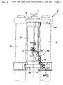
- Fig. 1 is a side view showing an essential portion of a motorcycle equipped with the steering damper device.
- Fig. 2 is a front view of a front fork portion as viewed from the direction of arrow 2 of Fig. 1.
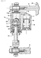
- Fig. 3 is a cross-sectional view of a cylindrical damper portion taken along line 3-3 of Fig. 2.
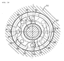
- Fig. 4 is an enlarged cross-sectional view taken along line 4-4 of Fig. 3.
- Fig. 5 is a cross-sectional view taken along line 5-5 of Fig. 4.
- Fig. 6 is a cross-sectional view taken along line 6-6 of Fig. 4.
- Fig. 1 is a side view showing an essential portion of a motorcycle equipped with the steering damper device.
- Fig. 2 is a front view of a front fork portion as viewed from the direction of arrow 2 of Fig. 1.
- Fig. 7 is an exploded perspective view of the piston of the cylindrical damper.
- Fig. 8 is a front view, as with Fig. 2, showing a state where a handlebar is turned from the neutral position to the left.
- Fig. 9 is a sectional view taken along line 9-9 of Fig. 8.
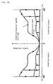
- Fig. 10 is a characteristic curve diagram of the steering damper device.
- a front fork 2 supporting a front wheel 1 of a motorcycle includes right and left fork pipes 3, 3 and a fork bridge 4 adapted to couple the upper end portions of the fork pipes 3, 3 together.
- the fork bridge 4 is comprised of a top bridge 4a and a bottom bridge 4b spaced vertically from and parallel to each other.
- a steering stem 5 is provided to connect the top and bottom bridges 4a, 4b at a horizontally central position therebetween.
- the steering stem 5 is rotatably inserted into a head pipe 6h provided at the front end of a body frame 6.
- a handlebar 7 is attached to the top bridge 4a for steering.
- the head pipe 6h is provided with a stay 8 projecting forward at a position closer to the lower end thereof.
- the stay 8 is located on the body-central plane extending in the longitudinal direction of the vehicle body.
- the bottom bridge 4b is provided with another stay 9 projecting forward at the horizontally central position thereof.
- the cylindrical damper 10 is mounted between both the stays 8, 9. In other words, the cylindrical damper 10 is disposed in front of the head pipe 6h, extending substantially along the longitudinal direction thereof.
- the cylindrical damper 10 is composed of a damper casing 11 and a damper rod 12 which is slidably displaced in the damper casing 11.
- the damper casing 11 is rotatably connected through a spherical joint 13 to a side of the head pipe 6h, i.e., to the stay 8 on the body side.
- the damper rod 12 is rotatably connected through a spherical joint 14 to a side of the bottom bridge 4b, i.e., to the stay 9 on the steering side.
- the central axis of the damper rod 12 slidably displaced in the damper casing 11, i.e., the central axis D of the cylindrical damper 10 is designed to extend along each of the central axes of the spherical joints 13, 14.
- the cylindrical damper 10 is mounted between the body frame 6 which is not turned even during the operation of the handlebar 7 and the front fork 2 which is turned by the operation of the handlebar 7.
- the cylindrical damper 10 is in the most contracted state when the handlebar 7 is in the neutral position, that is, when the steering angle of the handlebar 7 is 0o.
- the central axis D of the cylindrical damper 10 is allowed to be parallel to the central axis S of the steering stem 5.
- the central axis D of the cylindrical damper 10 is located on a plane in the longitudinal direction of the body, including the central axis S of the steering stem 5, that is, on the central plane of the body.
- the damper casing 11 of the cylindrical damper 10 includes, as shown in Fig. 3, a damper chamber 15 and a reservoir 17 communicating with the damper chamber 15 via an oil passage 16.
- the damper chamber 15 and the reservoir 17 are filled with oil.
- the bottom of the reservoir 17 is defined by a piston 18.
- the piston 18 is upwardly biased under pressure by a compressed gas 19 filled in a gas chamber located thereunder.
- the damper chamber 15 is partitioned into two chambers, i.e., upper and lower chambers 15a, 15b by a piston 20 attached to the top end of the damper rod 12.
- the piston 20 has a piston body 23 formed with pluralities of notches 21, 21, ... ; 22, 22, ... on the peripheries of the upper and lower portions thereof, respectively.
- the piston body 23 is provided with first through-holes 24, 24, ... and second through-holes 25, 25, ... , which pass vertically therethrough.
- the first through-holes 24 open at the respective upper ends into the upper end face of the piston body 23 and at the respective lower ends into the corresponding notches 22, 22, ... .
- the second through-holes 25 open at the respective lower ends into the lower end face of the piston body 23 and at the respective upper ends into the corresponding notches 21, 21, ... .
- the upper ends of the first through-holes 24 are controllably opened and closed by a valve plate 26 made of an elastic plate; the lower ends of the second through-hole 25 are controllably opened and closed by a similar valve plate 27.
- the upper valve plate 26 is at its central portion secured through a washer 29 with a nut 28 screwed onto the upper end of the damper rod 12.
- the upper valve plate 26 is at its peripheral portion biased downwardly under pressure through a washer 31 with a valve spring 30 disposed compressively between the upper end face of the damper chamber 15 and the washer 31. Consequently the upper valve plate 26 is normally maintained in close contact with the upper end face of the piston body 23.
- the washer 31 is also provided with a plurality of notches 31a, 31a, ... on the periphery thereof.
- a valve spring 33 is compressively disposed between the lower valve plate 27 and a valve receiver 32 carried by the damper rod 12.
- the lower valve plate 27 is at its central portion biased under pressure upwardly. Consequently the lower valve plate 27 is maintained in close contact with the lower end face of the piston body 23.
- the upper valve spring 30 has a sufficiently greater spring force than the lower valve spring 33.
- the cylindrical damper 10 is in the most contracted, i.e., the shortest state.
- the handlebar 7 is turned to the left for example, then the front fork 2 will be leftward turned around the steering stem 5 which is rotatably inserted into the head pipe 6h of the body frame 6.
- the bottom bridge 4b constitutes part of the fork bridge 4 of the front fork 2 is turned in the same way.
- the spherical joint 14 which couples the stay 9 provided in the horizontally central portion of the bottom bridge 4b to the damper rod 12 of the cylindrical damper 10 is offset from the body central plane extending in the longitudinal direction of the vehicle body.
- the spherical joint 13 which couples the stay 8 provided on the head pipe 6h to the damper casing 11 of the cylindrical damper 10 is not turned even if the handlebar 7 is turned.
- the spherical joint 13 is at the original position, that is, on the body central plane extending in the longitudinal direction of the vehicle body.
- the cylindrical damper 10 is extended, that is, the damper rod 12 is slidably displaced downwardly in the damper casing 11 in Fig. 3, which causes the damping force.
- the cylindrical damper 10 When the handlebar 7 is turned to the right, the cylindrical damper 10 is extended in the same way, that is, the damper rod 12 is slidably displaced downwardly in Fig. 3, which causes the damping force.
- the cylindrical damper 10 is configured such that even when the handlebar 7 is turned to either side, namely, to the right or left from the position where the steering angle of the handlebar 7 is 0o, the damper rod 12 is slidably displaced in the same direction in the damper casing 11.
- the amount of extension of the cylindrical damper 10 is the same if the cut angle, namely the steering angle of the handlebar 7 is the same.
- the damping force characteristics are symmetrical to each other as shown in Fig. 10.
- the cylindrical damper 10 When the handlebar 7 which has been turned to the right or left is returned to the neutral position, the cylindrical damper 10 is contracted in either case, that is, the damper rod 12 is slidably displaced within the damper casing 11 upwardly in Fig. 3. As described above, the cylindrical damper 10 is designed to scarcely generate the damping force. Therefore, the damping force is scarcely generated when the handlebar which has been turned is returned. In this way, the steering damper device can generate the damping force in either case, that is, when the handlebar 7 is turned to the right or left from the steering angle 0o. In addition, it can make the damping force smaller when the handlebar 7 is returned to the steering angle 0o.
- the amount of extension of the cylindrical damper 10 relative to the steering angle of the handlebar 7 is small when the handlebar 7 is in the vicinity of the neutral position; in the range of the larger steering angle of the handlebar 7, the damper stroke is gradually increased according to the steering angle of the handlebar 7. More specifically, the amount of slidable displacement of the damper rod 12 relative to the steering angle of the handlebar is small in the vicinity of 0o of the steering angle of the handlebar. In addition, it is increased as the steering angle of the handlebar is progressively changed from 0o. Thus, when the handlebar 7 is turned from the neutral position, damping moment is scarcely generated at its early stage, and gradually increased in the middle stage, as shown in Fig. 10.
- the damping force applied from the cylindrical damper 10 to the front fork 2 as the steering side member is small in the vicinity of 0o of the handlebar steering angle and it is increased according as the handlebar steering angle is progressively changed from 0o.
- the damping force continues smoothly from the early stage to the middle stage. In this way, this steering damper device can provide the characteristics desirable and preferable for steering damper devices for motorcycles.
- the damping coefficient of the cylindrical damper 10 i.e., the magnitude of the damping force relative to the amount of slidable displacement of the damper rod 12 is large when the damper 10 is contracted; it is smaller as the damper 10 is more extended. More specifically, the damping coefficient is large when the handlebar steering angle is in the vicinity of 0o; it is smaller as the handlebar steering angle is progressively changed from 0o. Accordingly, in the range of the increased handlebar steering angles, while the amount of the slidable displacement of the damper rod 12 relative to the steering angle of the handlebar is increased, the damping force is not increased so much. As a result, the increase in damping moment is small in the range of the increased steering angle of the handlebar; therefore, the handlebar can be operated nimbly even if it is turned fully to either side during the motorcycle is traveling at low speeds.
- Figs. 11 to 14 illustrate a steering damper device according to a second embodiment of the present invention.
- Fig. 11 is a longitudinal sectional side view showing an essential part of the cylindrical damper of the steering damper device.
- Fig. 12 is a longitudinal sectional side view showing the same as that of Fig. 11 but the operating state thereof.
- Fig. 13 is a cross-sectional view taken along line 13-13 in Fig. 11.
- Fig. 14 is a cross-sectional view taken line 14-14 in Fig. 11.
- the second embodiment is the same as the first embodiment in terms of the overall configuration but a cylindrical damper adopted.
- Components corresponding to those in the first embodiment are therefore denoted by the same reference numerals and the duplicate explanation will be omitted.
- a cylindrical damper 40 of the second embodiment is provided with a groove 41 on the circumferential wall of a damper chamber 15 in place of the valve spring 30 of the cylindrical damper 10 in the first embodiment.
- the piston body 23 of a piston 20 is attached to the top end of a damper rod 12 and is formed with pluralities of notches 21, 21, ... ; 22, 22, ... on the peripheries of the upper and lower portions thereof, respectively.
- the piston body 23 is provided with first through-holes 24, 24, ... and second through-holes 25, 25, ..., which pass vertically therethrough.
- the first through-holes 24 open at the respective upper ends into the upper end face of the piston body 23 and at the respective lower ends into the corresponding notches 22.
- the second through-holes 25 open at the respective lower ends into the lower end face of the piston body 23 and at the respective upper ends into the corresponding notches 21.
- the upper ends of the first through-holes 24 are controllably opened and closed by a valve plate 26 made of an elastic plate; the lower ends of the second through-holes 25 are controllably opened and closed by a similar valve plate 27.
- the upper valve plate 26 has relatively high-rigidity and is at its central portion secured through a washer 29 with a nut 28 screwed onto the upper end of the damper rod 12.
- the upper valve plate 26 is normally retained in close contact with the upper end face of the piston body 23.
- the lower valve plate 27 is at its central portion biased under pressure upwardly by a valve spring 33 compressively disposed between the valve plate 27 and a spring receiver 32 carried on the damper rod 12. Consequently the lower valve plate 27 is maintained in close contact with the lower end face of the piston body 23.
- the valve spring 33 has a small spring force.
- the damper chamber 15 is formed with the groove 41 on the circumferential wall at a location which faces the piston body 23 when the cylindrical damper 40 is extended.
- the groove 41 extends vertically greater than the vertical dimension of the piston body 23.
- the outer peripheral portion of the valve plate 26 is pushed up as denoted by double-dashed lines in Fig. 11, that is, separated from the upper end face of the piston body 23.
- the oil in the lower chamber 15b is allowed to flow to the upper chamber 15a as denoted by solid arrows in Fig. 11.
- resistance caused by the oil passing through the gap between the valve plate 26 and the piston body 23 generates a damping force.
- the valve plate 26 since the valve plate 26 has high-rigidity and is relatively less deformable, the gap defined between the valve plate 26 and the piston body 23 at that time is small. Accordingly, the damping coefficient of the damper 40 is large at that time.
- the steering damper device of the second embodiment can provides the same function and effect as that of the first embodiment.
- Figs. 15 to 18 illustrate a steering damper device according to a third embodiment of the present invention.
- Fig. 15 is a longitudinal sectional side view showing an essential part of the cylindrical damper of the steering damper device.
- Fig. 16 is a longitudinal sectional side view showing the same as that of Fig. 15 but the operating state thereof.
- Fig. 17 is a cross-sectional view taken along line 17-17 in Fig. 15.
- Fig. 18 is a cross-sectional view taken line 18-18 in Fig. 15.
- the third embodiment is the same as the first embodiment in terms of the overall configuration but a cylindrical damper adopted.
- Components corresponding to those in the first embodiment are therefore denoted by the same reference numerals and the duplicate explanation will be omitted.
- a cylindrical damper 50 of the third embodiment is provided with a passage 51 at the top end of a damper rod 12.
- a variable narrowing mechanism is provided in the passage 51.
- a piston 20 attached to the top end of the damper rod 12 has the same configuration as that of the second embodiment.
- the passage 51 is provided which is made up of a central hole 51a and radial holes 51b.
- the central hole 51a opens in the upper chamber 15a of a damper chamber 15 at the upper end face of the damper rod 12 and terminates at a position lower than the mounting portion of the piston 20.
- the radial holes 51b are adapted to establish communication between the central hole 15a and the lower chamber 15b of the damper chamber 15.
- the damper chamber 15 is at its upper end face formed with a tapered projection 52, which protrudes from the center of the upper end face downwardly and is reduced in diameter progressively downwardly.
- the projection 52 is inserted into the central hole 51a at the top end of the damper rod 12.
- the steering damper device of the third embodiment can provide the same function and effect as those of the first embodiment.
- Figs. 19 and 20 illustrate a steering damper device according to a fourth embodiment of the present invention.
- Fig. 19 is a side view of a fork bridge portion of a front fork in a motorcycle equipped with the steering damper device.
- Fig. 20 is a front view of the fork bridge portion as viewed from the direction of arrow 20.
- a substantially triangular link lever 58 is rotatably carried by the front end of a stay 8a through a horizontal shaft 59.
- the stay 8a projects forwardly from the vertically central portion of a head pipe 6h.
- a cylindrical damper 60 is disposed between the link lever 58 and the upper end of the head pipe 6h.
- the damper 60 is composed of a damper casing 61 and a damper rod 62 slidably displaced within the damper casing 61.
- the damper casing 61 is rotatably connected to the front of the upper end of the head pipe 6h through a horizontal shaft 63.
- the damper rod 62 is rotatably connected to the front end of the link lever 58 through a horizontal shaft 64.
- a link rod 65 is rotatably connected to the front of the lower end of the link lever 58 through a spherical joint 66.
- the other end of the link rod 65 is rotatably connected through a spherical joint 67 to the front of the horizontal central portion of a bottom bridge 4b, which is a lower part of the fork bridge 4.
- the cylindrical damper 60 is connected to a body frame 6 which is not turned even by operating a handlebar, while connected through the link lever 58 and the link rod 65 to the fork bridge 4 as a steering side member which is turned around a steering stem 5 by operating the handlebar.
- the link rod 65 is disposed in the following manner.
- a straight line L connecting the respective centers of the spherical joints 66, 67 is located on the central plane extending along the longitudinal direction of the vehicle body and including the central axis S of the steering stem 5.
- the spherical joints 66, 67 serve respectively as connecting parts at opposite ends of the link rod 65.
- the cylindrical damper 60 has the same configuration as those of the cylindrical dampers 10, 40, 50 in the first through third embodiments, respectively. When it is extended, a damping force is generated. In contrast, when it is contracted, the damping force is scarcely generated. In addition, its damping coefficient is large when the steering angle of the handlebar is in the vicinity of 0o; it is smaller as the steering angle is progressively changed from 0o.
- the damper 60 is extended to apply a damping force to the bottom bridge 4b as the steering side member.
- the spherical joint 66 on the side of the link lever 58 is pulled down, so that the damper is extended in the same way, generating the damping force.
- the damping coefficient is designed to be small at that time. This makes the damping force generated not large so much. Thus, this also prevents the rider from feeling hard steering.
- the steering damper device of the fourth embodiment can provide the same effect as that of the first embodiment.
- the movement of the steering side members is transmitted to the cylindrical damper 60 through the link rod 65 and the link lever 58; therefore, the damper 60 can be disposed so as to be disengaged from the steering side members and placed in any direction.
- the damper 60 can be arranged in a further free manner.
- the cylindrical damper 10 may be of a double-tube type in which a reservoir is provided on the outer circumference of the damper chamber in addition to a type in which the reservoir 17 is provided on the side of the damper chamber 15 as with each embodiment described above.
- a compression spring may be used in place of the compressed gas 19 for biasing the piston 18 provided on the side of the reservoir 17, and both may be provided.
- the present invention is applicable to four-wheel buggies and other vehicles in addition to the above-mentioned motorcycles.
- a cylindrical damper may be applicable in which it is the longest when the steering angle of a handlebar is near 0o and it can be disposed in the longitudinal direction of a vehicle body.
- the damper is not necessarily disposed in such a manner as to be located on the central plane in the longitudinal direction of the vehicle body when the handlebar 7 is on the neutral position.
- the damper can be disposed in such a manner as to be slightly offset from the central plane in the longitudinal direction of the vehicle body.
- the cylindrical damper 10 can be disposed between the body frame 6 and the top bridge 4a of the fork bridge 4 or the like.
Landscapes
- Engineering & Computer Science (AREA)
- General Engineering & Computer Science (AREA)
- Mechanical Engineering (AREA)
- Fluid-Damping Devices (AREA)
- Steering Devices For Bicycles And Motorcycles (AREA)
- Axle Suspensions And Sidecars For Cycles (AREA)
Claims (2)
- Dispositif d'amortisseur de direction comportant un amortisseur cylindrique (10, 40, 50, 60) qui peut être prévu entre un élément latéral de direction (4b) amené en rotation autour d'une tige de direction (5) en actionnant un guidon et un élément latéral de corps de véhicule (6h) non amené en rotation même en actionnant le guidon, l'amortisseur cylindrique (10, 40, 50, 60) présentant un carter d'amortisseur (11, 61) et une tige d'amortisseur (12, 62) qui est déplacée de manière coulissante dans le carter d'amortisseur (11, 61),
dans lequel une quantité de déplacement coulissant de la tige d'amortisseur (12, 62) par rapport à un angle de direction du guidon est faible lorsque l'angle de direction du guidon se situe au voisinage de 0° et la quantité de déplacement coulissant augmente à mesure que l'angle de direction s'éloigne progressivement de 0° ;
caractérisé en ce que
un coefficient d'amortissement de l'amortisseur cylindrique (10, 40, 50, 60), c'est-à-dire, la magnitude de la force d'amortissement par rapport à la quantité de déplacement coulissant de la tige d'amortisseur (12, 62) est importante lorsque l'angle de direction du guidon se situe au voisinage de 0° et le coefficient d'amortissement diminue lorsque l'angle de direction s'éloigne progressivement de 0°. - Dispositif d'amortisseur de direction selon la revendication 1, caractérisé en ce que
une force d'amortissement appliquée à l'élément latéral de direction (4b) depuis l'amortisseur cylindrique (10, 40, 50, 60) est faible lorsqu'un angle de direction du guidon se situe au voisinage de 0° et la force d'amortissement augmente à mesure que l'angle de direction s'éloigne progressivement de 0°.
Applications Claiming Priority (2)
| Application Number | Priority Date | Filing Date | Title |
|---|---|---|---|
| JP2004085400A JP4234045B2 (ja) | 2004-03-23 | 2004-03-23 | ステアリングダンパ装置 |
| JP2004085400 | 2004-03-23 |
Publications (2)
| Publication Number | Publication Date |
|---|---|
| EP1580110A1 EP1580110A1 (fr) | 2005-09-28 |
| EP1580110B1 true EP1580110B1 (fr) | 2007-11-21 |
Family
ID=34858418
Family Applications (1)
| Application Number | Title | Priority Date | Filing Date |
|---|---|---|---|
| EP05003158A Expired - Lifetime EP1580110B1 (fr) | 2004-03-23 | 2005-02-15 | Amortisseur de direction |
Country Status (6)
| Country | Link |
|---|---|
| US (1) | US7306248B2 (fr) |
| EP (1) | EP1580110B1 (fr) |
| JP (1) | JP4234045B2 (fr) |
| CN (1) | CN100372726C (fr) |
| DE (1) | DE602005003387T2 (fr) |
| TW (1) | TWI249489B (fr) |
Families Citing this family (17)
| Publication number | Priority date | Publication date | Assignee | Title |
|---|---|---|---|---|
| JP4206353B2 (ja) * | 2003-08-26 | 2009-01-07 | 本田技研工業株式会社 | ステアリングダンパ装置 |
| JP4825623B2 (ja) * | 2006-08-30 | 2011-11-30 | 本田技研工業株式会社 | 車両のステアリングダンパ取付構造 |
| JP5033456B2 (ja) * | 2007-03-30 | 2012-09-26 | 本田技研工業株式会社 | ステアリングダンパ取付構造 |
| JP2009006827A (ja) * | 2007-06-27 | 2009-01-15 | Showa Corp | 二輪車のステアリング減衰装置 |
| JP2009234515A (ja) * | 2008-03-28 | 2009-10-15 | Kayaba Ind Co Ltd | ステアリングダンパ |
| JP4972603B2 (ja) * | 2008-04-22 | 2012-07-11 | カヤバ工業株式会社 | ステアリングダンパ |
| JP5255329B2 (ja) * | 2008-06-04 | 2013-08-07 | ヤマハ発動機株式会社 | ステアリングダンパシステム及びそれを備えた鞍乗り型車両 |
| JP2012025181A (ja) * | 2010-07-20 | 2012-02-09 | Yamaha Motor Co Ltd | 鞍乗り型車両及び鞍乗り型車両に利用されるステアリングダンパ装置 |
| AR079383A1 (es) | 2010-12-27 | 2012-01-25 | Fischer Hugo Alfredo | Dispositivo estabilizador de direccion para vehiculos con columna y manillar. |
| DE102011009142B4 (de) | 2011-01-21 | 2017-03-16 | Edgar Uden | Stabilisierungssystem für Zweiräder |
| JP5675413B2 (ja) * | 2011-02-14 | 2015-02-25 | 本田技研工業株式会社 | 自動二輪車の車体フレーム |
| US9233729B2 (en) * | 2011-05-10 | 2016-01-12 | Yamaha Hatsudoki Kabushiki Kaisha | Steering damper control apparatus, and a saddle riding type vehicle having the same |
| JP6256837B2 (ja) * | 2014-03-10 | 2018-01-10 | 本田技研工業株式会社 | 鞍乗り型車両のステアリング構造 |
| US10173744B2 (en) * | 2015-10-05 | 2019-01-08 | Jeffrey M. Bales | Bicycle stabilizer devices and methods of stabilizing a bicycle |
| WO2018173167A1 (fr) * | 2017-03-22 | 2018-09-27 | 本田技研工業株式会社 | Amortisseur de direction |
| WO2021059856A1 (fr) * | 2019-09-27 | 2021-04-01 | 本田技研工業株式会社 | Véhicule de type à selle et dispositif de commande |
| JP2025069712A (ja) * | 2023-10-18 | 2025-05-01 | ヤマハ発動機株式会社 | 鞍乗型車両 |
Family Cites Families (13)
| Publication number | Priority date | Publication date | Assignee | Title |
|---|---|---|---|---|
| US615961A (en) * | 1898-12-13 | Steering-gear for bicycles | ||
| US2087535A (en) * | 1936-04-09 | 1937-07-20 | Dall John | Stabilizer |
| US4558878A (en) * | 1983-09-23 | 1985-12-17 | Motrenec Donald L | All terrain cycle with steering stabilizer |
| JPS61285186A (ja) * | 1985-06-11 | 1986-12-15 | ヤマハ発動機株式会社 | バ−ハンドル式車両の操向装置 |
| DE3629815A1 (de) * | 1986-09-02 | 1988-03-03 | Bayerische Motoren Werke Ag | Verfahren zum daempfen der lenkbewegungen |
| US5076383A (en) * | 1988-06-17 | 1991-12-31 | Honda Giken Kogyo Kabushiki Kaisha | Steering damper device |
| US5052528A (en) * | 1990-08-06 | 1991-10-01 | Rockwell International Corporation | Steering knuckle damper |
| US5161822A (en) * | 1990-11-26 | 1992-11-10 | Tlc Suspension | Tilt correction system |
| US5383676A (en) * | 1993-09-02 | 1995-01-24 | Valentino; Thomas J. | Centering apparatus for front wheel of three wheeled vehicle |
| US5620194A (en) * | 1995-06-07 | 1997-04-15 | The Boler Company | Self-steering suspension lockout mechanism |
| CN2276907Y (zh) * | 1996-06-21 | 1998-03-25 | 邹燕兴 | 可调式车把避震装置 |
| JP2003237672A (ja) * | 2002-02-20 | 2003-08-27 | Yamaha Motor Co Ltd | 自動二輪車用ステアリングダンパー |
| JP4206353B2 (ja) * | 2003-08-26 | 2009-01-07 | 本田技研工業株式会社 | ステアリングダンパ装置 |
-
2004
- 2004-03-23 JP JP2004085400A patent/JP4234045B2/ja not_active Expired - Fee Related
-
2005
- 2005-02-15 EP EP05003158A patent/EP1580110B1/fr not_active Expired - Lifetime
- 2005-02-15 DE DE602005003387T patent/DE602005003387T2/de not_active Expired - Lifetime
- 2005-02-21 TW TW094105062A patent/TWI249489B/zh not_active IP Right Cessation
- 2005-03-16 CN CNB2005100558729A patent/CN100372726C/zh not_active Expired - Fee Related
- 2005-03-21 US US11/084,016 patent/US7306248B2/en not_active Expired - Lifetime
Also Published As
| Publication number | Publication date |
|---|---|
| TWI249489B (en) | 2006-02-21 |
| DE602005003387D1 (de) | 2008-01-03 |
| CN100372726C (zh) | 2008-03-05 |
| DE602005003387T2 (de) | 2008-10-16 |
| JP2005271667A (ja) | 2005-10-06 |
| EP1580110A1 (fr) | 2005-09-28 |
| US20050212250A1 (en) | 2005-09-29 |
| US7306248B2 (en) | 2007-12-11 |
| CN1673022A (zh) | 2005-09-28 |
| JP4234045B2 (ja) | 2009-03-04 |
| TW200531873A (en) | 2005-10-01 |
Similar Documents
| Publication | Publication Date | Title |
|---|---|---|
| EP1580110B1 (fr) | Amortisseur de direction | |
| US6217049B1 (en) | Bicycle suspension system with spring preload adjuster and hydraulic lockout device | |
| US4433850A (en) | Front wheel suspension system for motorcycles | |
| CA2476975C (fr) | Dispositif amortisseur de direction | |
| CA2657851C (fr) | Systeme pour ajuster l'assiette de motocycles comportant trois ou quatre roues | |
| US7021433B2 (en) | Vehicle steering damper, steering damper kit for motorcycle, and motorcycle incorporating same | |
| JPS5981290A (ja) | 自動二輪車の制動時姿勢制御装置 | |
| US7390004B2 (en) | Steering damper device | |
| GB2573555A (en) | Steering centralisation device | |
| CN117533449A (zh) | 用于自行车的悬架部件 | |
| JP4637409B2 (ja) | フロントフォーク | |
| JP6256837B2 (ja) | 鞍乗り型車両のステアリング構造 | |
| US20060180416A1 (en) | Rotary damper | |
| EP3604103A1 (fr) | Amortisseur de direction | |
| JP4724213B2 (ja) | ステアリングダンパ装置 | |
| US11420704B2 (en) | Steering group of a motor vehicle and motor vehicle thereof | |
| JP4428806B2 (ja) | 車両の操舵装置 | |
| KR200318647Y1 (ko) | 자전거용 프레임의 충격흡수기구 | |
| JP4117098B2 (ja) | 二輪車の前輪支持用伸縮支柱 | |
| JPS61271184A (ja) | 自動二輪車の姿勢制御装置 | |
| JPH0347972Y2 (fr) | ||
| JPS6343275B2 (fr) | ||
| JP2006193155A (ja) | ステアリングダンパ装置 | |
| JPH02182577A (ja) | ラック・ピニオン式パワーステアリング装置 | |
| JP2005263000A (ja) | 自転車用の前輪懸架装置 |
Legal Events
| Date | Code | Title | Description |
|---|---|---|---|
| PUAI | Public reference made under article 153(3) epc to a published international application that has entered the european phase |
Free format text: ORIGINAL CODE: 0009012 |
|
| 17P | Request for examination filed |
Effective date: 20050215 |
|
| AK | Designated contracting states |
Kind code of ref document: A1 Designated state(s): AT BE BG CH CY CZ DE DK EE ES FI FR GB GR HU IE IS IT LI LT LU MC NL PL PT RO SE SI SK TR |
|
| AX | Request for extension of the european patent |
Extension state: AL BA HR LV MK YU |
|
| AKX | Designation fees paid |
Designated state(s): DE FR IT |
|
| GRAP | Despatch of communication of intention to grant a patent |
Free format text: ORIGINAL CODE: EPIDOSNIGR1 |
|
| GRAS | Grant fee paid |
Free format text: ORIGINAL CODE: EPIDOSNIGR3 |
|
| GRAA | (expected) grant |
Free format text: ORIGINAL CODE: 0009210 |
|
| AK | Designated contracting states |
Kind code of ref document: B1 Designated state(s): DE FR IT |
|
| REF | Corresponds to: |
Ref document number: 602005003387 Country of ref document: DE Date of ref document: 20080103 Kind code of ref document: P |
|
| ET | Fr: translation filed | ||
| PLBE | No opposition filed within time limit |
Free format text: ORIGINAL CODE: 0009261 |
|
| STAA | Information on the status of an ep patent application or granted ep patent |
Free format text: STATUS: NO OPPOSITION FILED WITHIN TIME LIMIT |
|
| 26N | No opposition filed |
Effective date: 20080822 |
|
| PGFP | Annual fee paid to national office [announced via postgrant information from national office to epo] |
Ref country code: DE Payment date: 20130213 Year of fee payment: 9 |
|
| REG | Reference to a national code |
Ref country code: DE Ref legal event code: R119 Ref document number: 602005003387 Country of ref document: DE |
|
| REG | Reference to a national code |
Ref country code: DE Ref legal event code: R119 Ref document number: 602005003387 Country of ref document: DE Effective date: 20140902 |
|
| PG25 | Lapsed in a contracting state [announced via postgrant information from national office to epo] |
Ref country code: DE Free format text: LAPSE BECAUSE OF NON-PAYMENT OF DUE FEES Effective date: 20140902 |
|
| REG | Reference to a national code |
Ref country code: FR Ref legal event code: PLFP Year of fee payment: 12 |
|
| REG | Reference to a national code |
Ref country code: FR Ref legal event code: PLFP Year of fee payment: 13 |
|
| REG | Reference to a national code |
Ref country code: FR Ref legal event code: PLFP Year of fee payment: 14 |
|
| PGFP | Annual fee paid to national office [announced via postgrant information from national office to epo] |
Ref country code: FR Payment date: 20180111 Year of fee payment: 14 Ref country code: IT Payment date: 20180221 Year of fee payment: 14 |
|
| PG25 | Lapsed in a contracting state [announced via postgrant information from national office to epo] |
Ref country code: IT Free format text: LAPSE BECAUSE OF NON-PAYMENT OF DUE FEES Effective date: 20190215 Ref country code: FR Free format text: LAPSE BECAUSE OF NON-PAYMENT OF DUE FEES Effective date: 20190228 |