EP1460221A2 - Structure porteuse - Google Patents
Structure porteuse Download PDFInfo
- Publication number
- EP1460221A2 EP1460221A2 EP04006167A EP04006167A EP1460221A2 EP 1460221 A2 EP1460221 A2 EP 1460221A2 EP 04006167 A EP04006167 A EP 04006167A EP 04006167 A EP04006167 A EP 04006167A EP 1460221 A2 EP1460221 A2 EP 1460221A2
- Authority
- EP
- European Patent Office
- Prior art keywords
- openings
- plate
- base plate
- fastening
- screws
- Prior art date
- Legal status (The legal status is an assumption and is not a legal conclusion. Google has not performed a legal analysis and makes no representation as to the accuracy of the status listed.)
- Withdrawn
Links
Images


Classifications
-
- E—FIXED CONSTRUCTIONS
- E05—LOCKS; KEYS; WINDOW OR DOOR FITTINGS; SAFES
- E05D—HINGES OR SUSPENSION DEVICES FOR DOORS, WINDOWS OR WINGS
- E05D7/00—Hinges or pivots of special construction
- E05D7/04—Hinges adjustable relative to the wing or the frame
- E05D7/0415—Hinges adjustable relative to the wing or the frame with adjusting drive means
- E05D7/0423—Screw-and-nut mechanisms
-
- E—FIXED CONSTRUCTIONS
- E05—LOCKS; KEYS; WINDOW OR DOOR FITTINGS; SAFES
- E05D—HINGES OR SUSPENSION DEVICES FOR DOORS, WINDOWS OR WINGS
- E05D5/00—Construction of single parts, e.g. the parts for attachment
- E05D5/02—Parts for attachment, e.g. flaps
- E05D5/04—Flat flaps
-
- E—FIXED CONSTRUCTIONS
- E05—LOCKS; KEYS; WINDOW OR DOOR FITTINGS; SAFES
- E05D—HINGES OR SUSPENSION DEVICES FOR DOORS, WINDOWS OR WINGS
- E05D7/00—Hinges or pivots of special construction
- E05D7/12—Hinges or pivots of special construction to allow easy detachment of the hinge from the wing or the frame
-
- E—FIXED CONSTRUCTIONS
- E05—LOCKS; KEYS; WINDOW OR DOOR FITTINGS; SAFES
- E05D—HINGES OR SUSPENSION DEVICES FOR DOORS, WINDOWS OR WINGS
- E05D3/00—Hinges with pins
- E05D3/02—Hinges with pins with one pin
- E05D2003/025—Hinges with pins with one pin having three knuckles
- E05D2003/027—Hinges with pins with one pin having three knuckles the end knuckles being mutually connected
-
- E—FIXED CONSTRUCTIONS
- E05—LOCKS; KEYS; WINDOW OR DOOR FITTINGS; SAFES
- E05D—HINGES OR SUSPENSION DEVICES FOR DOORS, WINDOWS OR WINGS
- E05D7/00—Hinges or pivots of special construction
- E05D7/04—Hinges adjustable relative to the wing or the frame
- E05D2007/0476—Pocket hinges
-
- E—FIXED CONSTRUCTIONS
- E05—LOCKS; KEYS; WINDOW OR DOOR FITTINGS; SAFES
- E05Y—INDEXING SCHEME ASSOCIATED WITH SUBCLASSES E05D AND E05F, RELATING TO CONSTRUCTION ELEMENTS, ELECTRIC CONTROL, POWER SUPPLY, POWER SIGNAL OR TRANSMISSION, USER INTERFACES, MOUNTING OR COUPLING, DETAILS, ACCESSORIES, AUXILIARY OPERATIONS NOT OTHERWISE PROVIDED FOR, APPLICATION THEREOF
- E05Y2900/00—Application of doors, windows, wings or fittings thereof
- E05Y2900/20—Application of doors, windows, wings or fittings thereof for furniture, e.g. cabinets
Definitions
- the invention relates to a substructure that can be fastened into a milled-out of a wooden frame by means of fastening screws for holding the frame-side hinge of a hinge band between a clamping plate and a counter-clamping plate, the clamping plate and the counter-clamping plate connecting clamping screw openings of the hinge plate reaching through with a two-dimensional insertion play, with the ends of the clamping plate reaching through Position adjustment of the same in a direction perpendicular to the hinge flap sit on a threaded spindle, which threaded spindles are each supported with their ends in a base plate and an angular cover plate that is riveted to the base plate, and the cover plate has openings for the fastening screw.
- a substructure is also previously known from DE 88 01191.7.
- the substructure is fastened there using fastening screws that are screwed through the ends of the cover plate.
- the spindles and the clamping screws lie in a common plane, which is defined by the fastening screws.
- a maximum of two fastening screws can be used.
- the invention has for its object to improve a generic substructure fastening technology.
- Claim 1 initially and essentially provides that the openings of the cover plate and openings of the clamping and counter-clamping plate arranged in alignment therewith have a diameter which is greater than the screw head diameter of the fastening screws connecting the base plate to the base of the cutout and are arranged such that the screw heads are covered by the held flap.
- the base plate can be screwed directly onto the base of the cutout.
- the heads of the screws move through the openings in the cover plate, clamping plate and counter-clamping plate. It is advantageous that this channel formed by the aligned push-through openings is closed by the inserted band tab. When fully assembled, the fastening screws are no longer accessible.
- the base plate is a stamped and bent part and two spacing webs are angled from a fastening section having the fastening openings for the fastening screws, from which fastening flaps which extend parallel to the base plate are angled in the form of wings and which are preferably angled from the end of a cover plate formed rivets are riveted.
- This solution brings increased stability to the entire substructure.
- the spacer webs lie in a common plane, as do the fastening tabs angled away therefrom.
- the fastening tabs have through openings for the threaded spindles mounted in the fastening section and in the cover plate.
- the threaded spindles can be plug-mounted in a simple manner. They are inserted through the through openings of the fastening tabs. A small-diameter end section of the threaded spindles is stored in a corresponding hole in the base plate. The other end of the threaded spindle, which has a hexagonal opening for inserting a screwing tool, is also reduced in diameter and is stored in a corresponding hole in the cover plate. It is also advantageous that the fastening section, the two spacer webs and the cover plate connecting the latter frame a window which extends in a parallel plane of an angle of the cover plate having a push-through slot for the band tab. The frame of this window gives the entire substructure increased stability.
- the base plate and the rivet connecting rivets are hollow rivets with a countersink for receiving a countersunk head of an additional fastening screw.
- the substructure can thus not only be held in the cut-out by more than two, in particular four fastening screws, these fastening screws connecting the base plate directly to the base of the frame, but also by additional fastening screws, which - as is known per se - in the ends of the Cover plate associated openings can be screwed.
- the cover plate thus has a plurality of openings, namely openings for inserting a screwing tool for tightening or loosening the clamping screws and openings for pushing through the fastening screws, the heads of which, however, are no longer visible when the hinge is inserted and are therefore not accessible.
- essentially cylindrical bearing sections of the threaded spindle lie in bearing openings of the base plate and are attached to the base plate essentially without play.
- the forces are now introduced directly into the base plate via the spindle. Wobbling is also effectively prevented.
- the spindle is now firmly attached to the base plate. Pressure forces are effectively kept away from the cover plate.
- the fastening of the bearing sections to the base plate is formed by screws which are screwed into the end faces of the threaded spindles.
- the screws can be countersunk screws.
- the threaded holes in the base plate and the end faces of the threaded spindles can then have countersinks. Sections of the truncated cone surfaces of the screws rest on these depressions. The truncated cone surfaces lie firmly on the depressions of the openings. But you can slide on it.
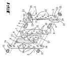
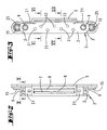
- Figures 1 to 9 show an embodiment of a substructure 1, which fulfills the function of a tape receiving element for tape hinges.
- the substructure 1 essentially consists of a frame bracket 2 forming a base plate, a cover bracket 5 forming a cover plate, a clamping plate 7 and a counter-clamping plate 8.
- the clamping is achieved with clamping screws 11.
- the door can be finely adjusted, since if the clamping screws 11 are not fully tightened, the frame flap 13 lying between the clamping plate 7 and the counter-clamping plate 8 can still be shifted slightly.
- the substructure 1 uses a stamped and bent part, the frame angle 2, as the base frame.
- This frame angle 2 consists of a base plate 3, from which two webs 21 project.
- a fastening tab in the form of a wing 22 is fastened to each of the two webs 21.
- Wing 22 and web 21 together with the associated section of base plate 3 form the shape of a U.
- the base part 3 formed by the base plate is elongated in shape, the ends 3 'of which are round.
- a cover bracket forms the cover plate 5 and extends parallel to the wings 22 and the bottom part 3, this has an elongated shape and covers the wings 22 of the frame bracket 2.
- the cover bracket 5 has two angle legs. One angle leg extends parallel to the bottom part 3. The other angle leg is angled at right angles to it and forms a window 6. In the assembled state, the angle leg of the cover bracket 5 forming the window 6 extends approximately between the two webs 21. As can be seen from FIG Margins of the webs 21 slightly.
- the angle leg of the cover bracket 5, which extends parallel to the base part 3, has a multiplicity of openings which are aligned with openings in the frame angle 2 and with openings of a clamping plate 7 and a counter-clamping plate 8 which will be explained further below.
- This clamping plate 7 and counter-clamping plate 8 are located in the space between the cover bracket 5 and the bottom part 3, the height of which is defined by the web 21.
- the clamping plate 7 is fixed in the intermediate space by means of threaded spindles 9.
- Each of the two threaded spindles 9 has a small-diameter bearing section 4 and a larger-diameter bearing section 1.
- the bearing sections 1, 4 are mounted in associated bearing openings 23 in the base part 3 and in the wing 22. By rotating the spindles 9, the position of the clamping plate 7 can be adjusted within the clearance space become.
- a counter clamping plate 8 is connected to the clamping plate 7 by means of clamping screws 11.
- Clamping plate 7 and counter-clamping plate 8 have openings 30 aligned with one another for pushing through fastening screws 10.
- the cover bracket 5 is firmly connected to the wings 22 of the frame bracket with two hollow rivets 15 which are riveted to rings 25.
- An opening 28 of the frame bracket 25 covers a bearing opening 23 for the spindle 9 in such a way that the spindle 9 is held axially in its bearing openings 23.
- the spindle 9 is accessed with a turning tool through the openings 28.
- a total of three openings 30 are aligned with one another, namely openings 30 of the frame bracket 5, the counter-clamping plate 8 and the clamping plate 7.
- the counter-clamping plate 8 is fastened to the clamping plate 7 by means of clamping screws 11.
- the counter-clamping plate 8 forms a fastening opening 27 with a countersink for receiving the countersunk head of the clamping screw 11.
- the clamping plate 7 forms a threaded bore 32 into which the thread of the clamping screw 11 can be screwed.
- the base part In aligned extension to the threaded bore 32, the base part has 2 bores 33, into which the portions of the threaded shaft of the threaded screw 11 projecting beyond the bore 32 can enter. Fastening openings 31 for the wood screws 10 are located adjacent to these inlet openings 33.
- the openings 30 form a channel through which wood screws 10 together with heads can be pushed.
- the base part 3 has openings 31 of smaller diameter, which are used for counterbores to receive the screw heads 10 'of the fastening screws 10.
- the substructure 1 with the base part 3 is placed on the base of the cutout 34 of a wooden door frame 18.
- Wood screws 10 which are pushed through the channel formed by openings 30, are screwed tight with a screwdriver 16.
- the blade of the screwdriver 16 projects through the channel formed by the openings 30 lying in the aligned position.
- the entire substructure is now fastened in the wooden door frame 18.
- the hinge 12 is attached to a wooden door 26.
- the frame tab 13 of the hinge 12 is designed in length and width so that it covers the wood screws after insertion into the substructure.
- C-shaped recesses 35 are provided in the frame tab 13, so that the height and depth of the hinge can be adjusted. The C-shaped recesses are penetrated by the clamping screws 11 with play.
- the wood screws 10 in the substructure 1 are completely covered by the C-shaped recesses 37 between fingers 37, whereby a loosening or removal of the substructure when the door 26 is mounted becomes impossible. If the door 26 is closed, both the spindles 9 and the clamping screws 11 are covered by the door, which prevents manipulation from the outside.
- the hollow rivets preferably form 15 countersinks, so that these hollow rivets can serve as additional fastening openings.
- leg of the cover bracket 5 forming the bores 30, 29 forms a cover plate and the base part 3 extending parallel thereto forms a base plate.
- the bearing section 4 of the threaded spindle with which the threaded spindle lies in a bearing opening 23 of the base plate, has an end-face threaded bore.
- a countersunk screw 38 is screwed into this threaded bore.
- the head 38 'of the countersunk screw 38 has a truncated cone surface 43 which slides on a depression 39 of the bore 23.
- the axial height of the cylindrical bearing section is less than the material thickness of the base plate.
- the threaded spindle is mounted on the base plate 3 with almost no play.
- the front threaded bore 40 also has a countersink 42.
- a section of the truncated cone section 43 is slidingly on this countersink 42.
- the threaded section 38 ′′ then engages in the thread of the threaded bore 40 in a rotationally fixed manner.
Landscapes
- Engineering & Computer Science (AREA)
- Mechanical Engineering (AREA)
- Auxiliary Devices For Music (AREA)
- Hinges (AREA)
Applications Claiming Priority (4)
| Application Number | Priority Date | Filing Date | Title |
|---|---|---|---|
| DE10312404 | 2003-03-20 | ||
| DE10312404 | 2003-03-20 | ||
| DE10347150 | 2003-10-10 | ||
| DE10347150A DE10347150B4 (de) | 2003-03-20 | 2003-10-10 | Unterkonstruktion |
Publications (2)
| Publication Number | Publication Date |
|---|---|
| EP1460221A2 true EP1460221A2 (fr) | 2004-09-22 |
| EP1460221A3 EP1460221A3 (fr) | 2009-03-18 |
Family
ID=32826220
Family Applications (1)
| Application Number | Title | Priority Date | Filing Date |
|---|---|---|---|
| EP04006167A Withdrawn EP1460221A3 (fr) | 2003-03-20 | 2004-03-16 | Structure porteuse |
Country Status (1)
| Country | Link |
|---|---|
| EP (1) | EP1460221A3 (fr) |
Cited By (2)
| Publication number | Priority date | Publication date | Assignee | Title |
|---|---|---|---|---|
| EP2551431A1 (fr) * | 2011-07-28 | 2013-01-30 | Bartels Systembeschläge GmbH | Penture compacte pour montage caché |
| WO2025011916A1 (fr) * | 2023-07-07 | 2025-01-16 | Christian Sitter | Charnière pour composants, de préférence pour assurer un support pivotant d'une porte ou d'une fenêtre dans un cadre |
Family Cites Families (2)
| Publication number | Priority date | Publication date | Assignee | Title |
|---|---|---|---|---|
| DE29817806U1 (de) * | 1998-10-06 | 1999-03-25 | Breuer & Schmitz, 42719 Solingen | Holzzargenkonstruktion insbesondere für Futterzargen |
| DE19923091A1 (de) * | 1999-05-20 | 2000-11-23 | Stoschek Bearbeitungs Gmbh | Bandaufnahmeelement zum Anlenken eines Türblattes an einen Türrahmen |
-
2004
- 2004-03-16 EP EP04006167A patent/EP1460221A3/fr not_active Withdrawn
Cited By (2)
| Publication number | Priority date | Publication date | Assignee | Title |
|---|---|---|---|---|
| EP2551431A1 (fr) * | 2011-07-28 | 2013-01-30 | Bartels Systembeschläge GmbH | Penture compacte pour montage caché |
| WO2025011916A1 (fr) * | 2023-07-07 | 2025-01-16 | Christian Sitter | Charnière pour composants, de préférence pour assurer un support pivotant d'une porte ou d'une fenêtre dans un cadre |
Also Published As
| Publication number | Publication date |
|---|---|
| EP1460221A3 (fr) | 2009-03-18 |
Similar Documents
| Publication | Publication Date | Title |
|---|---|---|
| AT6962U1 (de) | Scharnier | |
| EP2297418B1 (fr) | Charniere | |
| AT525067B1 (de) | Beschlag zur bewegbaren Lagerung eines Schwenkelementes relativ zu einem stationären Träger | |
| EP3613931B1 (fr) | Module de bande destiné au raccordement mobile par charnière autour d'un axe de charnière d'un battant sur un cadre | |
| AT15577U1 (de) | Band für eine Tür oder ein Fenster | |
| EP1984590A1 (fr) | Dispositif de fixation serrable | |
| WO1993021413A1 (fr) | Charniere de meuble | |
| EP3808997A1 (fr) | Dispositif goujon | |
| EP2949844B1 (fr) | Agencement de bande pour portes, fenêtres ou analogues, doté d'un dispositif de réglage de jeu de joint | |
| DE102010017121A1 (de) | Möbelscharnier | |
| DE10347150B4 (de) | Unterkonstruktion | |
| EP0991836B1 (fr) | Charniere pour portes d'armoire metallique | |
| EP1624144A2 (fr) | Charnière réglable montée par vissage | |
| EP2149664B1 (fr) | Structure de support pour une charnière et charnière dotée d'une telle structure de support destinée à la fixation sur un vantail de porte | |
| EP3219891A1 (fr) | Système de charnière à réglage tridimensionnelle | |
| DE7707895U1 (de) | Scharnier | |
| DE29920945U1 (de) | Möbelscharnier | |
| EP1454026B1 (fr) | Plaque de montage pour la fixation reglable de charnieres de meuble sur le corps de meubles | |
| EP2514892B1 (fr) | Système de fixation d'une partie de ferrure | |
| EP1106763B1 (fr) | Penture pour portes, fenêtres ou telles | |
| DE102007008963B3 (de) | Aufnahmeelement an Block- oder Futterzargen für einen Bandlappen eines Tür- oder Fensterbandes | |
| DE202013003742U1 (de) | Bandaufnahmeelement | |
| DE102012103140B4 (de) | Unterkonstruktion | |
| EP2540942B1 (fr) | Agencement de ferrure réglable | |
| DE102014103637B4 (de) | Topflocheinsatz, Blendenbefestigungselement und Topfscharnier |
Legal Events
| Date | Code | Title | Description |
|---|---|---|---|
| PUAI | Public reference made under article 153(3) epc to a published international application that has entered the european phase |
Free format text: ORIGINAL CODE: 0009012 |
|
| AK | Designated contracting states |
Kind code of ref document: A2 Designated state(s): AT BE BG CH CY CZ DE DK EE ES FI FR GB GR HU IE IT LI LU MC NL PL PT RO SE SI SK TR |
|
| AX | Request for extension of the european patent |
Extension state: AL LT LV MK |
|
| RAP1 | Party data changed (applicant data changed or rights of an application transferred) |
Owner name: GLUTZ DEUTSCHLAND GMBH |
|
| PUAL | Search report despatched |
Free format text: ORIGINAL CODE: 0009013 |
|
| AK | Designated contracting states |
Kind code of ref document: A3 Designated state(s): AT BE BG CH CY CZ DE DK EE ES FI FR GB GR HU IE IT LI LU MC NL PL PT RO SE SI SK TR |
|
| AX | Request for extension of the european patent |
Extension state: AL LT LV MK |
|
| AKX | Designation fees paid | ||
| STAA | Information on the status of an ep patent application or granted ep patent |
Free format text: STATUS: THE APPLICATION IS DEEMED TO BE WITHDRAWN |
|
| 18D | Application deemed to be withdrawn |
Effective date: 20090919 |
|
| REG | Reference to a national code |
Ref country code: DE Ref legal event code: 8566 |