EP1460245B1 - Dieselpartikelfiltereinheit und Steuerungsverfahren zum Regenerieren derselben - Google Patents
Dieselpartikelfiltereinheit und Steuerungsverfahren zum Regenerieren derselben Download PDFInfo
- Publication number
- EP1460245B1 EP1460245B1 EP04102471A EP04102471A EP1460245B1 EP 1460245 B1 EP1460245 B1 EP 1460245B1 EP 04102471 A EP04102471 A EP 04102471A EP 04102471 A EP04102471 A EP 04102471A EP 1460245 B1 EP1460245 B1 EP 1460245B1
- Authority
- EP
- European Patent Office
- Prior art keywords
- filter
- exhaust pressure
- ash
- regeneration
- value
- Prior art date
- Legal status (The legal status is an assumption and is not a legal conclusion. Google has not performed a legal analysis and makes no representation as to the accuracy of the status listed.)
- Expired - Lifetime
Links
Images





Classifications
-
- F—MECHANICAL ENGINEERING; LIGHTING; HEATING; WEAPONS; BLASTING
- F02—COMBUSTION ENGINES; HOT-GAS OR COMBUSTION-PRODUCT ENGINE PLANTS
- F02D—CONTROLLING COMBUSTION ENGINES
- F02D41/00—Electrical control of supply of combustible mixture or its constituents
- F02D41/02—Circuit arrangements for generating control signals
- F02D41/14—Introducing closed-loop corrections
- F02D41/1438—Introducing closed-loop corrections using means for determining characteristics of the combustion gases; Sensors therefor
- F02D41/1444—Introducing closed-loop corrections using means for determining characteristics of the combustion gases; Sensors therefor characterised by the characteristics of the combustion gases
- F02D41/1448—Introducing closed-loop corrections using means for determining characteristics of the combustion gases; Sensors therefor characterised by the characteristics of the combustion gases the characteristics being an exhaust gas pressure
-
- B—PERFORMING OPERATIONS; TRANSPORTING
- B01—PHYSICAL OR CHEMICAL PROCESSES OR APPARATUS IN GENERAL
- B01D—SEPARATION
- B01D53/00—Separation of gases or vapours; Recovering vapours of volatile solvents from gases; Chemical or biological purification of waste gases, e.g. engine exhaust gases, smoke, fumes, flue gases, aerosols
- B01D53/34—Chemical or biological purification of waste gases
- B01D53/92—Chemical or biological purification of waste gases of engine exhaust gases
- B01D53/94—Chemical or biological purification of waste gases of engine exhaust gases by catalytic processes
- B01D53/944—Simultaneously removing carbon monoxide, hydrocarbons or carbon making use of oxidation catalysts
-
- B—PERFORMING OPERATIONS; TRANSPORTING
- B01—PHYSICAL OR CHEMICAL PROCESSES OR APPARATUS IN GENERAL
- B01D—SEPARATION
- B01D53/00—Separation of gases or vapours; Recovering vapours of volatile solvents from gases; Chemical or biological purification of waste gases, e.g. engine exhaust gases, smoke, fumes, flue gases, aerosols
- B01D53/34—Chemical or biological purification of waste gases
- B01D53/92—Chemical or biological purification of waste gases of engine exhaust gases
- B01D53/94—Chemical or biological purification of waste gases of engine exhaust gases by catalytic processes
- B01D53/9495—Controlling the catalytic process
-
- F—MECHANICAL ENGINEERING; LIGHTING; HEATING; WEAPONS; BLASTING
- F01—MACHINES OR ENGINES IN GENERAL; ENGINE PLANTS IN GENERAL; STEAM ENGINES
- F01N—GAS-FLOW SILENCERS OR EXHAUST APPARATUS FOR MACHINES OR ENGINES IN GENERAL; GAS-FLOW SILENCERS OR EXHAUST APPARATUS FOR INTERNAL-COMBUSTION ENGINES
- F01N13/00—Exhaust or silencing apparatus characterised by constructional features
- F01N13/009—Exhaust or silencing apparatus characterised by constructional features having two or more separate purifying devices arranged in series
- F01N13/0097—Exhaust or silencing apparatus characterised by constructional features having two or more separate purifying devices arranged in series the purifying devices are arranged in a single housing
-
- F—MECHANICAL ENGINEERING; LIGHTING; HEATING; WEAPONS; BLASTING
- F01—MACHINES OR ENGINES IN GENERAL; ENGINE PLANTS IN GENERAL; STEAM ENGINES
- F01N—GAS-FLOW SILENCERS OR EXHAUST APPARATUS FOR MACHINES OR ENGINES IN GENERAL; GAS-FLOW SILENCERS OR EXHAUST APPARATUS FOR INTERNAL-COMBUSTION ENGINES
- F01N3/00—Exhaust or silencing apparatus having means for purifying, rendering innocuous, or otherwise treating exhaust
- F01N3/02—Exhaust or silencing apparatus having means for purifying, rendering innocuous, or otherwise treating exhaust for cooling, or for removing solid constituents of, exhaust
- F01N3/021—Exhaust or silencing apparatus having means for purifying, rendering innocuous, or otherwise treating exhaust for cooling, or for removing solid constituents of, exhaust by means of filters
- F01N3/023—Exhaust or silencing apparatus having means for purifying, rendering innocuous, or otherwise treating exhaust for cooling, or for removing solid constituents of, exhaust by means of filters using means for regenerating the filters, e.g. by burning trapped particles
-
- F—MECHANICAL ENGINEERING; LIGHTING; HEATING; WEAPONS; BLASTING
- F01—MACHINES OR ENGINES IN GENERAL; ENGINE PLANTS IN GENERAL; STEAM ENGINES
- F01N—GAS-FLOW SILENCERS OR EXHAUST APPARATUS FOR MACHINES OR ENGINES IN GENERAL; GAS-FLOW SILENCERS OR EXHAUST APPARATUS FOR INTERNAL-COMBUSTION ENGINES
- F01N3/00—Exhaust or silencing apparatus having means for purifying, rendering innocuous, or otherwise treating exhaust
- F01N3/02—Exhaust or silencing apparatus having means for purifying, rendering innocuous, or otherwise treating exhaust for cooling, or for removing solid constituents of, exhaust
- F01N3/021—Exhaust or silencing apparatus having means for purifying, rendering innocuous, or otherwise treating exhaust for cooling, or for removing solid constituents of, exhaust by means of filters
- F01N3/033—Exhaust or silencing apparatus having means for purifying, rendering innocuous, or otherwise treating exhaust for cooling, or for removing solid constituents of, exhaust by means of filters in combination with other devices
- F01N3/035—Exhaust or silencing apparatus having means for purifying, rendering innocuous, or otherwise treating exhaust for cooling, or for removing solid constituents of, exhaust by means of filters in combination with other devices with catalytic reactors
-
- F—MECHANICAL ENGINEERING; LIGHTING; HEATING; WEAPONS; BLASTING
- F01—MACHINES OR ENGINES IN GENERAL; ENGINE PLANTS IN GENERAL; STEAM ENGINES
- F01N—GAS-FLOW SILENCERS OR EXHAUST APPARATUS FOR MACHINES OR ENGINES IN GENERAL; GAS-FLOW SILENCERS OR EXHAUST APPARATUS FOR INTERNAL-COMBUSTION ENGINES
- F01N3/00—Exhaust or silencing apparatus having means for purifying, rendering innocuous, or otherwise treating exhaust
- F01N3/08—Exhaust or silencing apparatus having means for purifying, rendering innocuous, or otherwise treating exhaust for rendering innocuous
- F01N3/10—Exhaust or silencing apparatus having means for purifying, rendering innocuous, or otherwise treating exhaust for rendering innocuous by thermal or catalytic conversion of noxious components of exhaust
- F01N3/103—Oxidation catalysts for HC and CO only
-
- F—MECHANICAL ENGINEERING; LIGHTING; HEATING; WEAPONS; BLASTING
- F01—MACHINES OR ENGINES IN GENERAL; ENGINE PLANTS IN GENERAL; STEAM ENGINES
- F01N—GAS-FLOW SILENCERS OR EXHAUST APPARATUS FOR MACHINES OR ENGINES IN GENERAL; GAS-FLOW SILENCERS OR EXHAUST APPARATUS FOR INTERNAL-COMBUSTION ENGINES
- F01N9/00—Electrical control of exhaust gas treating apparatus
- F01N9/002—Electrical control of exhaust gas treating apparatus of filter regeneration
-
- F—MECHANICAL ENGINEERING; LIGHTING; HEATING; WEAPONS; BLASTING
- F02—COMBUSTION ENGINES; HOT-GAS OR COMBUSTION-PRODUCT ENGINE PLANTS
- F02D—CONTROLLING COMBUSTION ENGINES
- F02D41/00—Electrical control of supply of combustible mixture or its constituents
- F02D41/02—Circuit arrangements for generating control signals
- F02D41/021—Introducing corrections for particular conditions exterior to the engine
- F02D41/0235—Introducing corrections for particular conditions exterior to the engine in relation with the state of the exhaust gas treating apparatus
- F02D41/027—Introducing corrections for particular conditions exterior to the engine in relation with the state of the exhaust gas treating apparatus to purge or regenerate the exhaust gas treating apparatus
- F02D41/029—Introducing corrections for particular conditions exterior to the engine in relation with the state of the exhaust gas treating apparatus to purge or regenerate the exhaust gas treating apparatus the exhaust gas treating apparatus being a particulate filter
-
- F—MECHANICAL ENGINEERING; LIGHTING; HEATING; WEAPONS; BLASTING
- F02—COMBUSTION ENGINES; HOT-GAS OR COMBUSTION-PRODUCT ENGINE PLANTS
- F02D—CONTROLLING COMBUSTION ENGINES
- F02D41/00—Electrical control of supply of combustible mixture or its constituents
- F02D41/30—Controlling fuel injection
- F02D41/38—Controlling fuel injection of the high pressure type
- F02D41/40—Controlling fuel injection of the high pressure type with means for controlling injection timing or duration
- F02D41/402—Multiple injections
- F02D41/405—Multiple injections with post injections
-
- F—MECHANICAL ENGINEERING; LIGHTING; HEATING; WEAPONS; BLASTING
- F01—MACHINES OR ENGINES IN GENERAL; ENGINE PLANTS IN GENERAL; STEAM ENGINES
- F01N—GAS-FLOW SILENCERS OR EXHAUST APPARATUS FOR MACHINES OR ENGINES IN GENERAL; GAS-FLOW SILENCERS OR EXHAUST APPARATUS FOR INTERNAL-COMBUSTION ENGINES
- F01N2330/00—Structure of catalyst support or particle filter
- F01N2330/06—Ceramic, e.g. monoliths
-
- F—MECHANICAL ENGINEERING; LIGHTING; HEATING; WEAPONS; BLASTING
- F01—MACHINES OR ENGINES IN GENERAL; ENGINE PLANTS IN GENERAL; STEAM ENGINES
- F01N—GAS-FLOW SILENCERS OR EXHAUST APPARATUS FOR MACHINES OR ENGINES IN GENERAL; GAS-FLOW SILENCERS OR EXHAUST APPARATUS FOR INTERNAL-COMBUSTION ENGINES
- F01N2330/00—Structure of catalyst support or particle filter
- F01N2330/08—Granular material
-
- F—MECHANICAL ENGINEERING; LIGHTING; HEATING; WEAPONS; BLASTING
- F01—MACHINES OR ENGINES IN GENERAL; ENGINE PLANTS IN GENERAL; STEAM ENGINES
- F01N—GAS-FLOW SILENCERS OR EXHAUST APPARATUS FOR MACHINES OR ENGINES IN GENERAL; GAS-FLOW SILENCERS OR EXHAUST APPARATUS FOR INTERNAL-COMBUSTION ENGINES
- F01N2430/00—Influencing exhaust purification, e.g. starting of catalytic reaction, filter regeneration, or the like, by controlling engine operating characteristics
- F01N2430/08—Influencing exhaust purification, e.g. starting of catalytic reaction, filter regeneration, or the like, by controlling engine operating characteristics by modifying ignition or injection timing
-
- F—MECHANICAL ENGINEERING; LIGHTING; HEATING; WEAPONS; BLASTING
- F01—MACHINES OR ENGINES IN GENERAL; ENGINE PLANTS IN GENERAL; STEAM ENGINES
- F01N—GAS-FLOW SILENCERS OR EXHAUST APPARATUS FOR MACHINES OR ENGINES IN GENERAL; GAS-FLOW SILENCERS OR EXHAUST APPARATUS FOR INTERNAL-COMBUSTION ENGINES
- F01N2430/00—Influencing exhaust purification, e.g. starting of catalytic reaction, filter regeneration, or the like, by controlling engine operating characteristics
- F01N2430/08—Influencing exhaust purification, e.g. starting of catalytic reaction, filter regeneration, or the like, by controlling engine operating characteristics by modifying ignition or injection timing
- F01N2430/085—Influencing exhaust purification, e.g. starting of catalytic reaction, filter regeneration, or the like, by controlling engine operating characteristics by modifying ignition or injection timing at least a part of the injection taking place during expansion or exhaust stroke
-
- F—MECHANICAL ENGINEERING; LIGHTING; HEATING; WEAPONS; BLASTING
- F02—COMBUSTION ENGINES; HOT-GAS OR COMBUSTION-PRODUCT ENGINE PLANTS
- F02D—CONTROLLING COMBUSTION ENGINES
- F02D2200/00—Input parameters for engine control
- F02D2200/02—Input parameters for engine control the parameters being related to the engine
- F02D2200/08—Exhaust gas treatment apparatus parameters
- F02D2200/0812—Particle filter loading
-
- F—MECHANICAL ENGINEERING; LIGHTING; HEATING; WEAPONS; BLASTING
- F02—COMBUSTION ENGINES; HOT-GAS OR COMBUSTION-PRODUCT ENGINE PLANTS
- F02D—CONTROLLING COMBUSTION ENGINES
- F02D41/00—Electrical control of supply of combustible mixture or its constituents
- F02D41/02—Circuit arrangements for generating control signals
- F02D41/14—Introducing closed-loop corrections
- F02D41/1438—Introducing closed-loop corrections using means for determining characteristics of the combustion gases; Sensors therefor
- F02D41/1439—Introducing closed-loop corrections using means for determining characteristics of the combustion gases; Sensors therefor characterised by the position of the sensor
- F02D41/1441—Plural sensors
-
- Y—GENERAL TAGGING OF NEW TECHNOLOGICAL DEVELOPMENTS; GENERAL TAGGING OF CROSS-SECTIONAL TECHNOLOGIES SPANNING OVER SEVERAL SECTIONS OF THE IPC; TECHNICAL SUBJECTS COVERED BY FORMER USPC CROSS-REFERENCE ART COLLECTIONS [XRACs] AND DIGESTS
- Y02—TECHNOLOGIES OR APPLICATIONS FOR MITIGATION OR ADAPTATION AGAINST CLIMATE CHANGE
- Y02T—CLIMATE CHANGE MITIGATION TECHNOLOGIES RELATED TO TRANSPORTATION
- Y02T10/00—Road transport of goods or passengers
- Y02T10/10—Internal combustion engine [ICE] based vehicles
- Y02T10/40—Engine management systems
Definitions
- the present invention concerns a continuous regeneration type diesel particulate filter unit for cleaning the exhaust gas by capturing particulate of a diesel engine and a regeneration control method of the same.
- the restriction of discharge quantity of particulate (the PM: particulate: referred to as the PM hereinafter) discharged from the diesel engine is reinforced year by year together with NOx, CO and HC or the others. Therefore, a technique for reducing the quantity of the PM discharged outside, by capturing the PM by means of a filter called diesel particulate filer (DPF: Diesel Particulate Filter: referred to as DPF hereinafter) has been developed.
- DPF Diesel Particulate Filter: referred to as DPF hereinafter
- the DPF for capturing the PM includes monolith honeycomb form wall flow type filters made of ceramics, fiber filter type filters made of fiber shape ceramics or metal, or the others.
- the exhaust emission control device using these DPFs are installed in the middle of the engine exhaust pipe, similarly to the other exhaust emission control devices, for cleaning exhaust gas generated in the engine before discharging.
- the first of them concerns a regeneration unit and method of the same for using two filters alternately to capture the PM in exhaust gas by one filter and regenerate by burning the captured the PM heating by the other filter through an electric heater or the like.
- the second method and unit consists in using a solid filer as filter, disposing an oxidation catalyst upstream the solid filter, and treating the PM captured in the solid filter by a chemical reaction based on the oxidation catalyst.
- the third method and unit consists in using a solid filter provided with catalyst and a catalyst additive agent for accelerating the burning of the PM.
- Primary clogging factors of these DPF units include, in addition to smog or the like that are unburned components of the fuel and ash of burned lubricant oil.
- the lubricant oil is supplied to different parts of an engine and the periphery of piston rings from a lubricant oil reservoir to circulate in the engine, and penetrates into the engine cylinder from the peripheries of piston rings and valves.
- the ash captured by the filter is not burned and not removed by the filter regeneration operation or the others and accumulated in the filter even slightly.
- Lubricant oil leaks extremely slightly on the order of several tens of litter per ten thousand km of traveling; however, its total amount can not be neglected as the mileage increases. If the mileage attains the order of several ten thousand km or a hundred thousand km, the filter clogging due to the ash deposit and accumulation progresses, affecting the exhaust pressure before and after the filter.
- the clogging of filter due to the PM is judged by comparing the exhaust pressure measured before and after the filter and a predetermined exhaust pressure judgment value, and it is so controlled to start the filter regeneration operation, when exhaust pressure, difference pressure, pressure ratio or the others calculated from the measured exhaust pressure exceeds the predetermined judgment value.
- the PDF unit of the related art has a problem that the exhaust pressure raises gradually along with the increase of mileage, as the filter clogging due to ach generated from the lubricant oil is not considered, making the judgment to start the regeneration operation becomes gradually inappropriate.
- the second and the third units are units for lowering the burning start temperature of the PM by the function of a catalyst such as ⁇ alumina, Pt, zeolite, or the like supported by the filter, and incinerating the PM by the exhaust gas, called "continuous regeneration type DPF".
- the temperature of exhaust gas flowing in the PDF may be increased to a temperature for activating the catalyst (par example, equal or superior to 250 °C).
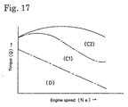
- the PM cleaning mechanism in the exhaust gas is different according to engine operation areas (torque and engine speed) (C1), (C2) as shown in Fig. 17.
- carbon (C : the PM) is oxidized to carbon dioxide (CO 2 ) through a reaction (4CeO 2 + C ⁇ 2CeO 3 + CO 2 , 2CeO 3 + O 2 ⁇ 4CeO 2 ) by catalytic action of the a filter with catalyst 4, while in the area (C2), carbon (C : the PM) is oxidized to carbon dioxide (CO 2 ) through a reaction (C + O 2 ⁇ CO 2 ).
- the fuel burns hardly, and a cool exhaust gas flows into the filter with catalyst, lowering the catalyst temperature and deteriorating the catalyst activity.
- the PM deposits on the filter during the driving period of time where the filter can not be regenerated.
- US-5,287,698 discloses an exhaust gas purifying device for an internal combustion engine.
- Said device comprises a trap into which particulate matter in an exhaust gas from an internal combustion engine is separated and collected, the particulate matter being burnable upon heating.
- parameters which are related to the rate at which particulate matter accumulates and is re-bumed, are monitored and the time at which a regeneration is required and/or the length of time a regeneration should be induced, is derived based on said parameters.
- the object of the present invention is to provide a diesel particulate fiilter unit (DPF unit) allowing to judge appropriately the start timing of regeneration operation, by estimating the state of accumulation of ash generated from a lubricant oil and correcting or compensating the exhaust pressure judgment value concerning the exhaust pressure used for judging the regeneration start, with the ash accumulated estimation value, and to remove the PM efficiently, all the way preventing the filter from clogging.
- DPF unit diesel particulate fiilter unit
- the DPF unit for achieving the object is configured as follows.
- a diesel filter unit comprising:
- the regeneration operation used often for a PDF unit changing over a plurality of filters alternately includes an operation to incinerate particulates by turning on a heating heater deposed in the filter and heating the filer to the particulate combustion temperature or higher.
- the regeneration operation for a DPF unit supporting a catalyst by the filter includes an operation for removing particulates through a chemical reaction by the catalyst, by raising the exhaust gas temperature.
- the judgment based on the comparison between the exhaust pressure measured by the exhaust pressure sensors and the predetermined exhaust pressure judgment value includes manners of judgment described below, or manners of judgment by the combination thereof; however, the other judgments may be adopted provided that they use the exhaust pressure and the predetermined exhaust pressure judgment value.
- One of them consists in comparing the exhaust pressure Pe measured by an exhaust pressure sensors disposed upstream the filter and a predetermined exhaust pressure judgment value Pes, and starting the regeneration operation when the measured exhaust pressure Pe exceeds the predetermined exhaust pressure judgment value Pes.
- a map data Mash (Q, Ne) and a function fash (Q, Ne) are prepared, and they are used.
- the map date Mash is to be determined beforehand from the relation between the torque Q of an engine and the engine speed Ne obtained by experiment and computation, and the ash quantity Ash to be accumulated in the filter during such engine operation state.
- the ash quantitiy can be determined from the quantity of lubricant oil consumed according to the engine operation state, by means of experiment or computation. Besides, as an ash quantity is produced on the order of 8 g to 10 g by one (1) litter of lubricant oil, the map data Mash (Q, Ne) and the function fash (Q, Ne) can also be obtained by converting the exhaust pressure increment due to the clogging of the filter with the ash quantity, from the ash quantity.
- an exhaust pressure coefficient ⁇ 1 corresponding to the ash accumulated estimation value SAsh ⁇ (Ash ⁇ ⁇ t) is calculated, the reference judgment value ⁇ Pe0, Pe0, Re0 is multiplied by the exhaust pressure coefficient ⁇ 1 to determined the value of ⁇ 1 ⁇ Pe0, ⁇ 1 ⁇ Pe0, ⁇ 1 ⁇ Re0 and the reference judgment value ⁇ Pe0, Pe0, Re0 is replaced, by the value, to correct
- the reference judgment value ⁇ Pe0, Pe0, Re0 for judging the regeneration start timing concerning the operation state of an engine presenting an engine torque Q and an engine speed Ne is obtained beforehand by experiment or computation, they are prepared as map data M ⁇ pe0 (Q, Ne), Mpe0 (Q, Ne), Mre0 (Q, Ne) or function f ⁇ pe0(Q, Ne), fpe0(Q, Ne), fre0(Q, Ne), and they are used.
- the regeneration control method of the DPF unit for achieving the aforementioned object is configured as follows.
- Regeneration control method of a diesel particulate filter unit comprising:
- the ash quantity accumulating in the filter is calculated from the torque of the engine and the engine speed, using the relation between torque of the engine and engine speed and ash accumulation quantity, determined beforehand through experiment or computation, and the ash accumulated estimation value can be estimated correctly by a simple algorithm, by calculating the accumulated estimation value through a cumulative computation of the ash quantity.
- the reference judgment value is calculated from the torque of engine and the engine speed of the time when the exhaust pressure for judging the regeneration start timing, using the relation between torque of the engine and engine speed and ash accumulation quantity, determined beforehand through experiment or computation, and the exhaust pressure judgment value is calculated from the reference judgment value, the measured exhaust pressure and the exhaust pressure judgment value for comparison judgment result in being able to be compared one the other for the operation state of a same engine. Consequently, the difference of exhaust pressure due to the difference of operation state of the engine is cancelled, the judgment of regeneration start timing can be performed more finely and appropriately.
- the regeneration start timing of the filter of the DPF unit can be judged correctly, even when the mileage of a diesel engine vehicle having the DPF unit on board. Consequently, it can travel removing the PM efficiently by preventing the fitter from clogging.
- DPF unit diesel particulate filter unit
- Fig. 1 shows the composition of a DPF unit 1 of the first embodiment
- the DPF unit 1 shown in Fig. 1 is a continuous regeneration type DPF unit, installed in a exhaust passage 2 of an engine E, having an oxidation catalyst 3 and a filter with catalyst 4 disposed from the upstream side.
- a first exhaust pressure sensors 51 is installed at the exhaust entrance side of the oxidation catalyst 3, and, a second exhaust pressure sensors 52 is installed at the exhaust exit side of the filter with catalyst 4, for controlling the regeneration of the filter with catalyst 4.
- Output values Pe, Peb from these sensors are input to an engine control unit (ECU : Engine Control Unit) 5 controlling generally the engine operation and, at the same time, Including a regeneration control means 50 for performing regeneration control and regeneration operation of the filter with catalyst 4, and a control signal output from the control unit 5 controls a fuel injection unit 6 of the engine E.
- ECU Engine Control Unit
- the oxidation catalyst 3 is formed by supporting an oxidation catalyst such as platinum (Pt)/ ⁇ alumina or the others, on a support of honeycomb structure made of porous ceramics or the others.
- the filter of the filter with catalyst 4 is formed with a monolith honeycomb form wall flow type filer where the inlet and the outlet of a channel of a honeycomb made of porous ceramics are obtruded alternately, a felt shape filter made by laminating randomly organic fibers of alumina or the like, or the others. It is composed by supporting a catalyst such as platinum (Pt)/ ⁇ alumina or the others on a portion of the filter.
- particulates in an exhaust gas G are trapped by a porous ceramic wall.
- the PM are trapped by organic fibers of the filter.
- the regeneration control method is executed by a control program loaded on the control unit 5, or a regeneration control means 50 formed of a control program loaded on the control unit 5, input/output units, or the others, and the judgment of the start of regeneration operation is performed according to a judgment flow of regeneration start timing as illustrated in Fig. 2.
- the judgment flow of regeneration start timing as illustrated is executed in parallel with a (not shown) control flow of the engine E, and a correction flow of exhaust pressure judgment value as shown in Fig. 3 described below.
- a judgment of regeneration operation start is performed by inputting, an exhaust pressure judgment value ⁇ Pes for judgment of regeneration operation start corrected by the correction flow of the exhaust pressure judgment value of Fig. 3, and in case of judging as start timing, an indication of starting the regeneration mode operation which is a regeneration process is emitted.
- an exhaust pressure Pe measured by the first exhaust pressure sensors 51 installed upstream the filter 4 and an exhaust pressure Peb measured by the second exhaust pressure sensors 52 installed downstream the filter 4 are input for judging the regeneration control start, in a step S110.
- a step S140 the differential pressure ⁇ Pe and a predetermined exhaust pressure judgment value ⁇ Pes are compared, and when the measured exhaust pressure ⁇ Pe exceeds the predetermined exhaust pressure judgment value ⁇ Pes, the start of regeneration mode operation is indicated in a step S150 before return, and if not exceeding, it returns as it is.
- the exhaust gas temperature raises and the oxidation catalyst 3 is activated by the retard of main injection and, furthermore, by the execution of post injection, in the fuel injection control.
- the PM is removed through chemical reaction by the catalyst supported by the filter with catalyst 4, thus regenerating the filter with catalyst 4.
- exhaust pressure judgment value ⁇ Pes for judging the regeneration control start to be used for the foregoing, it is so configured that the ash accumulated quantity SAsh of combustion remaining ash of lubricant oil of the engine E leaked into the exhaust gas G and accumulated in the filter 4 is estimated and the exhaust pressure judgment value ⁇ Pes is corrected and compensated based on the ash accumulated estimation value SAsh.
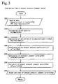
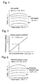
- step S210 When the flow starts, first of all, in a step S210, torque Q and engine speed Ne indicating the operation state of the engine E are input. In a following step S220, from these torque Q and engine speed Ne, the ash quantity Ash of ash to be accumulated in the filter 4 within a unit time ( ⁇ t) are calculated from a preliminarily input map data Mash (Q, Ne) as shown in Fig. 4.
- the ash quantity Ash of ash to be accumulated in the filter with catalyst 4 corresponding the torque Q and engine speed Ne is determined, through a preliminary experiment, computation or the others, and input beforehand in the regeneration control means 50. It should be appreciated that it may be input beforehand in the regeneration control means 50, as a function fash (Q, Ne) calculating As from Q and Ne in place of map data.
- an exhaust pressure coefficient ⁇ 1 corresponding to the ash accumulated estimation value SAsh is calculated, and in a step S250, an reference judgment value ⁇ Pe0 in an operation state of an engine E is determined from the torque Q and engine speed Ne of that engine E of the time when exhaust pressures Pe, Peb for judgment of regeneration start timing are measured by the exhaust pressure sensors 51, 52.
- reference judgment value ⁇ Pe0 In the calculation of reference judgment value ⁇ Pe0 also, the reference judgment value ⁇ Pe0(Q, Ne) for judgment of start timing of regeneration operation concerning the operation state of an engine of engine torque Q and engine speed Ne is determined beforehand by experiment or computation, and the same is prepared as map data M ⁇ pe (Q, Ne) or function f ⁇ pe0 (Q, Ne) and the same is used.
- the ash quantity Ash accumulating in the filter with catalyst 4 is calculated, using the relation between torque Q of engine and engine speed Ne, and ash accumulation quantity Ash accumulating or depositing in the filter with catalyst 4 in such engine operation state, and the ash accumulated estimation value can be estimated correctly by a simple algorithm, by calculating the accumulated estimation value SAsh through a cumulative computation of the ash quantity.
- the reference judgment value ⁇ Pe0 is calculated from the torque Q of engine and the engine speed Ne, determined beforehand through experiment or computation, the measured exhaust pressure Pe, Peb and the exhaust pressure judgment value ⁇ Pes for comparison can be compared one the other for the operation state of a same engine. Consequently, the difference of exhaust pressure Pe, Peb due to the difference of operation state of the engine is cancelled, and the judgment of regeneration start timing can be performed more finely.
- the DPF unit and regeneration control method of the present invention includes not only these DPF units and regeneration control methods thereof, but also the other DPF units and regeneration control methods thereof using the exhaust pressure for judging the start timing of regeneration operation.
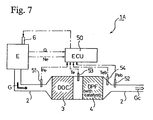
- Fig. 7 shows the composition of the continuous regeneration type DPF unit of the second embodiment.
- the continuous regeneration type DPF unit 1A is a unit installed in an exhaust passage 2 of an engine E, having an oxidation catalyst 3 and a filter with catalyst 4 disposed from the upstream side.
- a first exhaust pressure sensors 51 is installed at the exhaust entrance side of the oxidation catalyst 3, and, first temperature sensors 53 between the oxidation catalyst 3 and the filter with catalyst 4, a second exhaust pressure sensors 52 and a second temperature sensors 54 at the exhaust exit side of the filter with catalyst 4, for controlling the regeneration of the filter with catalyst 4.
- Output values from these sensors are input to an engine control unit (ECU : Engine Control Unit) 5 performing a general control of the engine operation and, at the same time, performing the regeneration control of the filter with catalyst 4, and a control signal output from the control unit 5 controls a fuel injection unit 6 of the engine.
- ECU Engine Control Unit
- the oxidation catalyst 3 is formed by supporting an oxidation catalyst such as platinum (Pt)/ ⁇ alumina, zeolite or the others, on a support of honeycomb structure made of porous ceramics or the others, and the filter with catalyst 4 is formed with a monolith honeycomb form wall flow type filer where the inlet and the outlet of a channel of a honeycomb made of porous ceramics are obtruded alternately, a felt shape filter made by laminating randomly organic fibers of alumina or the like, or the others. It is composed by supporting a catalyst such as Pt, ⁇ alumina, zeolite or the others on a portion of the filter.
- a catalyst such as Pt, ⁇ alumina, zeolite or the others on a portion of the filter.
- particulates in an exhaust gas G are trapped by a porous ceramic wall, while in case of adopting a fiber form filter type, the PM are trapped by organic fibers of the filter.
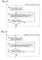
- the regeneration control method is executed according to a flow as illustrated in Fig. 8 to fg13.
- regeneration control flows called and executed reiteratively, in parallel with a control flow of the engine E.
- the flow is called and executed reiteratively every fixed time in parallel during the operation control of the engine E, and upon termination of the control of the engine E, these flows are not called no more, and substantially, the regeneration operation of the filter with catalyst 4 terminates at the same time.
- the regeneration control flow is configured to start the regeneration mode operation not only when the exhaust pressure Pe to be detected by the first exhaust pressure sensors 51 exceeds a predetermined first exhaust pressure judgment value Pemax, but also when the accumulation quantity of the PM in the filter with catalyst 4, namely the PM accumulated estimation value the PMs exceeds a predetermined the PM judgment value the PMmax.
- the flow of the regeneration mode operation in the step S30 is composed of a series of operations including a cut of EGR (exhaust gas recirculate combustion) in a step S31, a temperature elevation first stage for preheating by retarding the timing of main injection of fuel injection in a step S32, a temperature elevation second stage for performing a post injection in a step S33 and injection of a fixed quantity of fuel for starting the PM combustion, a temperature elevation third stage for burning the PM by incrementing the injection quantity of post injection in a step S34, a temperature elevation fourth stage for purging the PM by incrementing further the injection quantity of post injection in a step S35, and a termination of regeneration mode operation in a step S36.
- EGR exhaust gas recirculate combustion
- a DPF entrance temperature Tb at the balance point (BP) is calculated from these torque Q and engine speed Ne by means of a preliminarily input map data Mtb (Q, Ne).
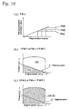
- a measured DPF entrance temperature Te is equal or inferior to the DPF entrance temperature Tb at the balance point or not, namely, if it is in the area (portion A in Fig. 15) of the PM accumulation where the operation state of the engine E is in low torque and low revolution speed or not.
- step S13 if the measured DPF entrance temperature Te is equal or inferior to the DPF entrance temperature Tb at the balance point, namely, if it is in the PM accumulation area (A), in a step S14, the deposited the PM quantity for every such time on the filter corresponding to the torque Q and engine speed Ne is calculated from a preliminarily input the PMa (Q, Ne) map data of Fig. 15(b), and this the deposited the PM quantity is added to the PM accumulated estimation value the PMs, before Return.
- step S16 it is judged if the PM accumulated estimation value the PMs is larger than zero or not, namely, if the PM is in a deposited state or not and, in the judgment of the step S16, in case where the PM accumulated estimation value the PMs is smaller than zero, the PM accumulated estimation value the PMs is set to zero in a step S17 before Return, and in case of larger than zero, Return as it is.
- step S21 of Fig. 8 it is judged if the PM accumulated estimation value the PMs exceeds the predetermined the PM judgment value the PMmax, or if the exhaust pressure Pe exceeds the predetermined first exhaust pressure judgment value Pemax, and more precisely, the judgment of the PM accumulated estimation value the PMs is controlled to enter the regeneration mode operation in case where the PM accumulated estimation value the PMs is between the PM1 and the PM2, as shown in Fig. 16(a), and the operation state of engine (torque Q, engine speed Ne) is in an oblique line portion (A) under the balance point of Fig. 16(b) and in case where the PM accumulated estimation value the PMs is between the PM2 and the PM3. It should be appreciated that, in case of between the PM2 and the PM3, the operation state of engine (torque Q, engine speed Ne) is in an oblique line portion (A+B) of Fig. 16(c), namely, in the full operation state.
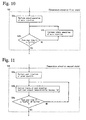
- step S32 of Fig. 8 the timing of the main injection of fuel injection is retarded, and the exhaust gas temperature is raised by the retard operation; however, in the step S32, as shown in a detail flow of Fig. 10, in a step S32a, the main injection is retarded, and the exhaust gas temperature is raised by the retard operation.
- the post ignition is performed, and a fixed quantity of fuel is post injected. Furthermore, the exhaust gas temperature is raised until the DPF entrance temperature Te attains a second target temperature Te2.
- the second target temperature Te2 is a temperature allowing the PM to burn as shown in Fig. 15, higher than the DPF entrance temperature Tb at the balance point by a predetermined temperature (for example 50 °C), of the order of about 250 °C to 350 °C.
- step S33 a post injection of a fixed quantity is performed in a step S33a, and further, the DPF entrance temperature Te is raised to the second target temperature Te2.
- the post injection timing is controlled until the exhaust pressure Pe (or differential pressure ⁇ Pe) becomes equal or inferior to a predetermined second exhaust pressure value Pe2b (or second differential pressure ⁇ Pe2) and the second target temperature Te2 is maintained. Also, it can be maintained by controlling the injection quantity.
- a step S33c it is judged either if the exhaust pressure Pe (or differential pressure ⁇ Pe) has become equal or inferior to the predetermined second exhaust pressure value Pe2 (or second differential pressure ⁇ Pe2), or the second target temperature Te2 is maintained for a predetermined second time value t2 (for example 300s) and if either one is the case, it shifts to a step S34, and neither on is the case, it returns to the step S33b.
- the start of the PM combustion can be confirmed by the fact that the exhaust pressure Pe (or differential pressure ⁇ Pe) becomes equal or inferior to the predetermined second exhaust pressure value Pe2 (or second differential pressure ⁇ Pe2).
- the ignition amount of post ignition is incremented, the exhaust gas temperature is raised and controlled to be appropriate for the PM combustion, namely, so that the DPF entrance temperature Te becomes a third target temperature Te3 which is superior to the second target temperature Te2.
- the third target temperature Te3 is a temperature higher than the DPF entrance temperature Tb at the balance point by a predetermined temperature (for example 150 °C), of the order of about 350°C to 500 °C.
- a step S34c it is judged either if the exhaust pressure Pe (or differential pressure ⁇ Pe) has become equal or inferior to the predetermined third exhaust pressure value Pe3 (or third differential pressure ⁇ Pe3), or the third target temperature Te3 is maintained for a predetermined third time value t3 (for example 600s) and if either one is the case, it shifts to a step S35, and neither one is the case, it returns to the step S34b.
- step S35 in Fig. 8 the ignition amount of post ignition is further incremented and controlled so that the DPF entrance temperature Te becomes a fourth target temperature Te4 (for example 600 °C).
- step S35 as shown in a detailed flow of Fig. 13, the ignition amount of post ignition is incremented in a step S35a.
- step S35b the injection quantity of post injection is controlled until the exhaust pressure Pe (or differential pressure ⁇ Pe) becomes equal or inferior to a predetermined fourth exhaust pressure value Pe4 (or fourth differential pressure A Pe4) and the DPF entrance temperature Te is maintained at the fourth target temperature Te4.
- step S36 shown in Fig. 8 the regeneration mode operation is terminated, the fuel injection is reset to the normal, and at the same time, the PM computation cumulative value the PMs is reset to zero.
- the torque is decreased automatically, or other engine running operations are performed for preventing the filter with catalyst 4 from fusion damage.
- the PM remaining quantity the PMs' is estimated from exhaust pressure Pe' at the previous regeneration termination, exhaust pressure Pe" at the beginning of regeneration of this time, and exhaust pressure Pe at the regeneration interruption, and the PM remaining quantity the PMs' is adopted as the value at the beginning of integration of the PM accumulated estimation value the PMs.
- the relation among the first exhaust pressure value Pemax, the second exhaust pressure value Pe2 (or second differential pressure value ⁇ Pe2), the third exhaust pressure value Pe3 (or third differential pressure value ⁇ Pe3), and the fourth exhaust pressure value Pe4 (or fourth differential pressure ⁇ Pe4) decreases in the order. In short, they are in a relation of Pemax > Pe2 > Pe3 > Pe4 (or ⁇ Pe2 > ⁇ Pe3 > ⁇ Pe4).
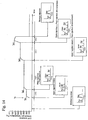
- the regeneration of the filter with catalyst 4 is performed in a time series of the DPF entrance temperature Te as shown in Fig. 14, as mentioned below.
- the PM accumulated estimation value the PMs becomes superior to a predetermined judgment value the PMmax or the exhaust pressure Pe becomes superior to the first exhaust pressure value Pemax, it shifts to the regeneration mode of the step S30, by the judgment of the step S21 in Fig. 8.
- EGR exhaust gas recirculate combustion
- the injection quantity of post injection is incremented, and the DPF entrance temperature Te is controlled to maintain the third target temperature Te3 (about 500 °C), so that the exhaust gas temperature becomes a temperature appropriate for the PM combustion, and the PM combustion is performed at a temperature optimal for the PM combustion.
- the termination of the PM combustion is confirmed by the fact that the exhaust pressure Pe (or differential pressure ⁇ Pe) becomes equal or inferior to the predetermined fourth exhaust pressure value Pe4 (or fourth differential pressure ⁇ Pe4), and in the step S36, the regeneration mode operation is terminated, the fuel injection is reset to the normal, and at the same time, the PM computation cumulative value the PMs is reset to zero.
- the oxidation catalyst disposed upstream the continuous regeneration type filter with catalyst can oxidize carbon monoxide (CO) and unburned fuel (HC) or the like in the exhaust gas, for raising the exhaust gas temperature flowing into the filter with catalyst; therefore, the temperature of the filter with catalyst can raise even in an engine operation state at a relatively low exhaust gas temperature, allowing to burn and remove particulates (the PM) being captured.
- CO carbon monoxide
- HC unburned fuel
- the PM can be burned and removed by raising the exhaust gas temperature, through retard operation of main injection timing of fuel injection and post injection.
- combustion of particulate can be controlled by controlling the exhaust gas temperature through retard operation of main injection timing or post injection of fuel injection, without using a heating heater, the fuel injection can be performed by a fuel injection control unit which is already installed; therefore, it becomes unnecessary to install additionally a heater for heating, a power supply, or other new equipment or new control units, allowing to make the unit compact.
- the temperature of exhaust gas entering the filter with catalyst is raised in two (2) stages or in multiple stages, allowing to prevent a sudden elevation of temperature provoked by a sudden combustion of deposited the PM in a chain reaction manner, and to avoid the fusion damage of the filter with catalyst.
- the regeneration mode operation is entered based on the PM accumulated estimation value by the computation, the regeneration processing of the filter with catalyst can be performed at an optimal timing. Therefore, the particulate can be captured, burned and removed efficiently, all the way preventing the fuel efficiency from deteriorating.
- a preliminarily heating is performed by the elevation of exhaust gas temperature and the oxidation catalyst is preheated when the regeneration mode operation starts, and then the post injection is performed, allowing to prevent generation of white smoke, that otherwise appears often during the regeneration start.
Landscapes
- Engineering & Computer Science (AREA)
- Chemical & Material Sciences (AREA)
- Combustion & Propulsion (AREA)
- General Engineering & Computer Science (AREA)
- Mechanical Engineering (AREA)
- Chemical Kinetics & Catalysis (AREA)
- Health & Medical Sciences (AREA)
- Biomedical Technology (AREA)
- Environmental & Geological Engineering (AREA)
- Analytical Chemistry (AREA)
- General Chemical & Material Sciences (AREA)
- Oil, Petroleum & Natural Gas (AREA)
- Toxicology (AREA)
- Materials Engineering (AREA)
- Processes For Solid Components From Exhaust (AREA)
Claims (2)
- Dieselfiltereinheit (1), welche folgendes beinhaltet:einen Filter (4) zum Einfangen von teilchenförmigen Stoffen in Abgas (G) aus einem Dieselmotor (E), in einer Abgasleitung (2) vorgesehene Abgasdrucksensoren (51, 52) undeine Regenerationssteuerungsvorrichtung (5), die auf Basis des Ergebnisses einer Beurteilung bzw. Feststellung aus einem Vergleich der von den Abgasdrucksensoren (51, 52) gemessenen Abgasdrücke (Pe, Peb) mit dem vorbestimmten Abgasdruck-Beurteilungswert (ΔPes, Pes oder Res) eine Regenerationsoperation für den Filter (4) durchführt und durch Entfernen von teilchenförmigen Feststoffen, die von dem Filter (4) eingefangen wurden, mittels Verbrennen oder durch eine chemische Reaktion durch einen Katalysator den Filter (4) regeneriert, wobei die Regenerationssteuervorrichtung (50) so angeordnet ist, daß sie eine Schätzung einer angesammelten Menge (Sash) an Asche, die in das Abgas (G) abgegeben wurde und nicht durch Verbrennen durch die Regenerationsoperation für den Filter (4) entfernt werden kann, sondern sich in dem Filter (4) ansammelt, durchführt und den Abgasdruck-Beurteilungswert (ΔPes, Pes oder Res) für eine Beurteilung bzw. Feststellung des Beginns der Regenerationsoperation auf Basis des geschätzten Werts der angesammelten Aschemenge (Sash) korrigiert, dadurch gekennzeichnet, daß die Regenerationssteuerungsvorrichtung (50) eine Aschemenge (Ash), die sich während eines Betriebszustands des Motors in dem Filter (4) angesammelt hat, aus einem Drehmoment (Q) des Motors (E) und einer Motorgeschwindigkeit (Ne) berechnet und den geschätzten Asche-Ansammlungswert (Sash) durch die kumulative Berechnung der berechneten Aschemenge (Ash) berechnet, wobei die Regenerationssteuerungsvorrichtung (50) einen Abgasdruckkoeffizienten (α1) berechnet, der dem geschätzten Asche-Ansammlungswert (Sash) entspricht, und den Abgasdruck-Beurteilungswert (ΔPes, Pes oder Res) auf einen Wert korrigiert, der durch Multiplizieren eines Referenz-Beurteilungswerts (ΔPe0, Pe0 oder Re0) mit dem Abgasdruckkoeffizienten (α1) bestimmt wird, wobei die Regenerationssteuerungsvorrichtung (50) den Referenz-Beurteilungswert (ΔPe0, Pe0 oder Re0) aus dem Drehmoment (Q) des Motors (E) und der Motorgeschwindigkeit (Ne) berechnet, wenn der Abgasdruck (Pe, Peb) für die Feststellung des Startzeitpunkts der Regeneration von den Abgasdrucksensoren (51, 52) gemessen wird.
- Regenerationssteuerungsverfahren für eine Dieselpartikelfiltereinheit (1), welche folgendes beinhaltet:einen Filter (4) zum Einfangen von teilchenförmigen Feststoffen in Abgas (G) aus einem Dieselmotor (E),in einer Abgasleitung (2) vorgesehene Abgasdrucksensoren (51, 52) und eine Regenerationssteuerungsvorrichtung (50), die auf Basis des Ergebnisses einer Beurteilung bzw. Feststellung aus einem Vergleich der von den Abgasdrucksensoren (51, 52) gemessenen Abgasdrücke (Pe, Peb) mit den vorbestimmten Abgasdruck-Beurteilungswerten (ΔPes, Pes oder Res) eine Regenerationsoperation für den Filter (4) durchführt und durch Entfernen von durch den Filter (4) eingefangenen teilchenförmigen Feststoffen mittels Verbrennen oder durch eine chemische Reaktion durch einen Katalysator den Filter (4) regeneriert,wobei das Regenerationssteuerungsverfahren folgendes umfaßt:den Schritt des Einstellens einer Ansammlungsmenge (Sash) von in das Abgas (G) abgegebener Asche, die nicht durch Verbrennen durch die Regenerationsoperation für den Filter (4) entfernt werden kann, sondern sich in dem Filter (4) ansammelt, undden Schritt des Korrigierens der Abgasdruck-Beurteilungswerte (ΔPes, Pes oder Res) für eine Feststellung des Beginns der Regenerationsoperation auf Basis des geschätzten Werts der angesammelten Aschemenge (Sash), dadurch gekennzeichnet, daß das Verfahren die Stufen umfaßt, bei denen man eine Aschemenge (Ash), die sich während eines Betriebszustands des Motors in dem Filter (4) angesammelt hat, aus dem Drehmoment (Q) des Motors (E) und der Motorgeschwindigkeit (Ne) berechnet, den geschätzten Asche-Ansammlungswert (Sash) durch kumulative Berechnung der berechneten Aschemenge (Ash) berechnet, einen Abgasdruckkoeffizienten (α1) berechnet, der dem geschätzten Asche-Ansammlungswert (Sash) entspricht, den Abgasdruck-Beurteilungswert (ΔPes, Pes oder Res) auf einen Wert korrigiert, der durch Multiplizieren eines Referenz-Beurteilungswerts (ΔPe0, Pe0 oder Re0) mit dem Abgasdruckkoeffizienten (α1) bestimmt wird, und den Referenz-Beurteilungswert (ΔPe0, Pe0 oder Re0) aus dem Drehmoment (Q) des Motors (E) und der Motorgeschwindigkeit (Ne) berechnet, wenn die Abgasdrücke (Pe, Peb) zur Feststellung des Startzeitpunkts der Regeneration von den Abgasdrucksensoren (51, 52) gemessen werden.
Applications Claiming Priority (5)
| Application Number | Priority Date | Filing Date | Title |
|---|---|---|---|
| JP2001044445A JP3951618B2 (ja) | 2001-02-21 | 2001-02-21 | ディーゼルパティキュレートフィルタ装置とその再生制御方法 |
| JP2001044445 | 2001-02-21 | ||
| JP2001046993 | 2001-02-22 | ||
| JP2001046993A JP3951619B2 (ja) | 2001-02-22 | 2001-02-22 | 連続再生型ディーゼルパティキュレートフィルタ装置及びその再生制御方法 |
| EP02003221A EP1234959B1 (de) | 2001-02-21 | 2002-02-20 | Dieselpartikelfiltereinheit und Steuerungsverfahren zum Regenerieren derselben |
Related Parent Applications (2)
| Application Number | Title | Priority Date | Filing Date |
|---|---|---|---|
| EP02003221.5 Division | 2002-02-20 | ||
| EP02003221A Division EP1234959B1 (de) | 2001-02-21 | 2002-02-20 | Dieselpartikelfiltereinheit und Steuerungsverfahren zum Regenerieren derselben |
Publications (2)
| Publication Number | Publication Date |
|---|---|
| EP1460245A1 EP1460245A1 (de) | 2004-09-22 |
| EP1460245B1 true EP1460245B1 (de) | 2007-04-11 |
Family
ID=26609779
Family Applications (2)
| Application Number | Title | Priority Date | Filing Date |
|---|---|---|---|
| EP04102471A Expired - Lifetime EP1460245B1 (de) | 2001-02-21 | 2002-02-20 | Dieselpartikelfiltereinheit und Steuerungsverfahren zum Regenerieren derselben |
| EP02003221A Expired - Lifetime EP1234959B1 (de) | 2001-02-21 | 2002-02-20 | Dieselpartikelfiltereinheit und Steuerungsverfahren zum Regenerieren derselben |
Family Applications After (1)
| Application Number | Title | Priority Date | Filing Date |
|---|---|---|---|
| EP02003221A Expired - Lifetime EP1234959B1 (de) | 2001-02-21 | 2002-02-20 | Dieselpartikelfiltereinheit und Steuerungsverfahren zum Regenerieren derselben |
Country Status (3)
| Country | Link |
|---|---|
| US (1) | US6622480B2 (de) |
| EP (2) | EP1460245B1 (de) |
| DE (2) | DE60219522T2 (de) |
Cited By (1)
| Publication number | Priority date | Publication date | Assignee | Title |
|---|---|---|---|---|
| CN101458108B (zh) * | 2007-12-14 | 2012-10-10 | 现代自动车株式会社 | 用于计算柴油机微粒过滤器的有效容积的方法和装置 |
Families Citing this family (172)
| Publication number | Priority date | Publication date | Assignee | Title |
|---|---|---|---|---|
| JP4161546B2 (ja) * | 2001-06-26 | 2008-10-08 | いすゞ自動車株式会社 | 連続再生型ディーゼルパティキュレートフィルタ装置の再生制御方法 |
| KR100504422B1 (ko) * | 2001-09-07 | 2005-07-29 | 미쓰비시 지도샤 고교(주) | 엔진의 배기 정화 장치 |
| JP4022723B2 (ja) * | 2002-01-11 | 2007-12-19 | 株式会社デンソー | 排気フィルタ再生装置及び方法 |
| JP3879833B2 (ja) * | 2002-03-04 | 2007-02-14 | 三菱自動車工業株式会社 | 内燃機関の排気浄化装置 |
| DE10213170A1 (de) * | 2002-03-23 | 2003-10-02 | Daimler Chrysler Ag | Betriebsverfahren für eine mit einem Abgasnachbehandlungssystem arbeitende Brennkraftmaschine |
| US7055309B2 (en) * | 2002-03-27 | 2006-06-06 | Robert Bosch Gmbh | Method and device for controlling an internal combustion engine |
| SE522146C2 (sv) * | 2002-05-07 | 2004-01-20 | Volvo Lastvagnar Ab | Metod för regenerering av ett partikelfilter vid motorbromsning samt fordon i vilket en sådan metod utnyttjas |
| JP3969196B2 (ja) * | 2002-06-04 | 2007-09-05 | 株式会社デンソー | 内燃機関の燃料噴射制御装置 |
| JP3922107B2 (ja) * | 2002-06-14 | 2007-05-30 | 株式会社デンソー | 内燃機関の排気ガス浄化装置 |
| DE10234791A1 (de) * | 2002-07-31 | 2004-02-19 | Deutz Ag | Aschebeladungsermittlung für Partikelfilter |
| JP3824979B2 (ja) * | 2002-08-09 | 2006-09-20 | ボッシュ株式会社 | フィルタ制御方法及び装置 |
| JP3869333B2 (ja) * | 2002-08-12 | 2007-01-17 | ボッシュ株式会社 | 排気ガス浄化装置 |
| WO2004016916A1 (ja) * | 2002-08-13 | 2004-02-26 | Bosch Automotive Systems Corporation | フィルタ制御装置 |
| US20120116645A1 (en) * | 2002-08-13 | 2012-05-10 | Toshihiro Hamahata | Filter controller system |
| JP4505176B2 (ja) * | 2002-09-17 | 2010-07-21 | いすゞ自動車株式会社 | 内燃機関の排気ガス浄化システム |
| FR2846049B1 (fr) * | 2002-10-18 | 2006-06-23 | Renault Sa | Procede de regeneration d'un filtre a particules et dispositif de mise en oeuvre |
| DE10252732B4 (de) * | 2002-11-13 | 2010-07-08 | Robert Bosch Gmbh | Verfahren und Vorrichtung zum Betrieb einer Abgasnachbehandlungseinrichtung einer Brennkraftmaschine |
| JP4157752B2 (ja) * | 2002-11-19 | 2008-10-01 | カルソニックカンセイ株式会社 | エンジンの排気熱回収装置 |
| JP3801135B2 (ja) * | 2003-01-08 | 2006-07-26 | 日産自動車株式会社 | エンジンの排気ガス浄化装置 |
| JP3912289B2 (ja) * | 2003-01-10 | 2007-05-09 | 日産自動車株式会社 | パティキュレートフィルタの再生装置及びエンジンの排気ガス浄化装置 |
| JP3864910B2 (ja) * | 2003-01-10 | 2007-01-10 | 日産自動車株式会社 | 内燃機関の排気浄化装置 |
| JP2004225579A (ja) * | 2003-01-21 | 2004-08-12 | Isuzu Motors Ltd | 排気ガス浄化システム |
| DE10310024B4 (de) * | 2003-02-28 | 2012-09-27 | Volkswagen Ag | Verfahren zur Aufheizung eines Katalysators |
| US7062906B2 (en) * | 2003-03-03 | 2006-06-20 | Nissan Motor Co., Ltd. | Regeneration of particulate filter |
| JP2004293340A (ja) * | 2003-03-25 | 2004-10-21 | Mitsubishi Fuso Truck & Bus Corp | 排ガス浄化装置 |
| JP2004293339A (ja) * | 2003-03-25 | 2004-10-21 | Mitsubishi Fuso Truck & Bus Corp | 排ガス浄化装置 |
| JP4288985B2 (ja) * | 2003-03-31 | 2009-07-01 | 株式会社デンソー | 内燃機関の排気浄化装置 |
| JP4103665B2 (ja) * | 2003-04-02 | 2008-06-18 | 日産自動車株式会社 | 排気浄化装置 |
| US6892531B2 (en) * | 2003-04-02 | 2005-05-17 | Julius J. Rim | System for and methods of operating diesel engines to reduce harmful exhaust emissions and to improve engine lubrication |
| JP4048993B2 (ja) * | 2003-04-08 | 2008-02-20 | 日産自動車株式会社 | エンジンの排気浄化装置 |
| JP4139259B2 (ja) * | 2003-04-08 | 2008-08-27 | 日野自動車株式会社 | パティキュレートフィルタの再生方法 |
| KR100469066B1 (ko) * | 2003-04-14 | 2005-02-02 | 에스케이 주식회사 | 디젤차량 입자상 물질 제거용 필터 및 이의 제조방법 |
| JP4225153B2 (ja) * | 2003-07-30 | 2009-02-18 | 日産自動車株式会社 | 排気フィルタの再生制御装置 |
| FR2858355B1 (fr) * | 2003-07-31 | 2005-10-28 | Peugeot Citroen Automobiles Sa | Procede et dispositif de depollution des gaz d'echappement d'un moteur a combustion interne |
| JP4320621B2 (ja) * | 2003-08-25 | 2009-08-26 | 株式会社デンソー | 内燃機関の排気浄化装置 |
| JP2005090256A (ja) * | 2003-09-12 | 2005-04-07 | Toyota Motor Corp | 内燃機関の排気浄化装置における圧力検出機構 |
| DE602004032094D1 (de) * | 2003-09-17 | 2011-05-19 | Nissan Motor | Vorrichtung zur Steuerung der Regeneration eines Diesel-Partikelfilters |
| JP2005090359A (ja) * | 2003-09-17 | 2005-04-07 | Nissan Motor Co Ltd | Dpfの再生制御装置 |
| JP4131219B2 (ja) * | 2003-09-18 | 2008-08-13 | 日産自動車株式会社 | ディーゼルエンジンの排気後処理装置 |
| DE602004004221T2 (de) * | 2003-09-19 | 2007-05-03 | Nissan Motor Co., Ltd., Yokohama | Regenerationssteuerung eines Filters |
| US20070227120A1 (en) * | 2003-10-08 | 2007-10-04 | The Lubrizol Corporation | System Containing Oxygen Enriched Diesel Particulate Filter and Method Thereof |
| FR2862086B1 (fr) * | 2003-11-07 | 2006-02-17 | Peugeot Citroen Automobiles Sa | Systeme d'aide a la maintenance d'un filtre a particules integre dans une ligne d'echappement d'un moteur de vehicule automobile |
| FR2862099B1 (fr) | 2003-11-07 | 2006-04-14 | Peugeot Citroen Automobiles Sa | Systeme d'aide a la regeneration de moyens de depollution integres dans une ligne d'echappement d'un moteur diesel de vehicule |
| FR2862097B1 (fr) | 2003-11-07 | 2006-02-17 | Peugeot Citroen Automobiles Sa | Systeme d'aide a la regeneration de moyens de depollution integres dans une ligne d'echappement d'un moteur diesel de vehicule |
| FR2862102B1 (fr) * | 2003-11-07 | 2007-06-22 | Peugeot Citroen Automobiles Sa | Systeme d'aide a la regeneration de moyens de depollution d'un moteur de vehicule |
| FR2862098B1 (fr) | 2003-11-07 | 2006-02-17 | Peugeot Citroen Automobiles Sa | Systeme d'aide a la regeneration de moyens de depollution integres dans une ligne d'echappement d'un moteur diesel de vehicule |
| FR2862100B1 (fr) * | 2003-11-07 | 2008-04-04 | Peugeot Citroen Automobiles Sa | Systeme d'aide a la regeneration de moyens de depollution integres dans une ligne d'echappement d'un vehicule |
| EP1541837B1 (de) * | 2003-12-08 | 2012-09-05 | Nissan Motor Co., Ltd. | Regenerationsmethode und Steuerung eines Dieselpartikelfilters |
| FR2863654B1 (fr) * | 2003-12-16 | 2007-08-10 | Renault Sas | Procede de regeneration d'un filtre a particules a impregnation catalytique |
| JP4269927B2 (ja) * | 2003-12-17 | 2009-05-27 | トヨタ自動車株式会社 | 内燃機関の排気浄化システム |
| DE10359395A1 (de) * | 2003-12-18 | 2005-07-21 | Daimlerchrysler Ag | Verfahren zum Betreiben eines Partikelfilters im Abgasstrang einer Brennkraftmaschine eines Kraftfahrzeugs |
| US7581389B2 (en) * | 2004-01-13 | 2009-09-01 | Emcon Technologies Llc | Method and apparatus for monitoring ash accumulation in a particulate filter of an emission abatement assembly |
| EP1718389A4 (de) * | 2004-01-13 | 2012-05-09 | Emcon Technologies Llc | Abgasentgiftungsanordnung und betriebsverfahren dafür |
| JP4211611B2 (ja) * | 2004-01-14 | 2009-01-21 | トヨタ自動車株式会社 | 内燃機関の排気浄化装置 |
| JP2005248787A (ja) * | 2004-03-03 | 2005-09-15 | Mitsubishi Fuso Truck & Bus Corp | 排気浄化装置 |
| KR100879326B1 (ko) * | 2004-03-11 | 2009-01-19 | 도요타 지도샤(주) | 내연기관용 배기정화장치 및 배기정화방법 |
| JP4314134B2 (ja) * | 2004-03-11 | 2009-08-12 | トヨタ自動車株式会社 | 内燃機関排気浄化装置の粒子状物質再生制御装置 |
| JP4049113B2 (ja) * | 2004-03-11 | 2008-02-20 | トヨタ自動車株式会社 | 内燃機関排気浄化装置の粒子状物質再生制御装置 |
| JP4038187B2 (ja) * | 2004-03-11 | 2008-01-23 | トヨタ自動車株式会社 | 内燃機関排気浄化装置の粒子状物質再生制御装置 |
| JP4170935B2 (ja) * | 2004-03-11 | 2008-10-22 | トヨタ自動車株式会社 | 内燃機関の排気浄化装置 |
| JP4125255B2 (ja) * | 2004-03-11 | 2008-07-30 | トヨタ自動車株式会社 | 内燃機関の排気浄化装置 |
| JP4314135B2 (ja) * | 2004-03-11 | 2009-08-12 | トヨタ自動車株式会社 | 車載内燃機関の排気浄化装置 |
| JP4434038B2 (ja) * | 2004-04-05 | 2010-03-17 | 株式会社デンソー | 内燃機関の排気浄化装置 |
| JP4161930B2 (ja) * | 2004-04-06 | 2008-10-08 | いすゞ自動車株式会社 | 排気ガス浄化システムの制御方法及び排気ガス浄化システム |
| JP4148178B2 (ja) * | 2004-04-08 | 2008-09-10 | いすゞ自動車株式会社 | 排気ガス浄化システムの制御方法及び排気ガス浄化システム |
| FR2869639B1 (fr) * | 2004-04-29 | 2009-06-12 | Peugeot Citroen Automobiles Sa | Procede de determination de la charge d'un piege pour substances polluantes |
| KR100622708B1 (ko) * | 2004-06-01 | 2006-09-14 | 현대자동차주식회사 | 디젤 매연 여과장치의 재생 방법 |
| DE102004026589A1 (de) * | 2004-06-01 | 2006-01-19 | Siemens Ag | Verfahren zur Überwachung eines Partikelfilters |
| FR2872200B1 (fr) * | 2004-06-23 | 2006-11-03 | Peugeot Citroen Automobiles Sa | Systeme d'aide a la regeneration de moyens de depollution associes a des moyens formant catalyseur |
| FR2872203B1 (fr) * | 2004-06-23 | 2006-11-03 | Peugeot Citroen Automobiles Sa | Systeme d'aide a la regeneration de moyens de depollution |
| FR2872211B1 (fr) * | 2004-06-23 | 2006-09-29 | Peugeot Citroen Automobiles Sa | Systeme d'evaluation de l'etat de charge en suies de moyens de depollution |
| FR2872213B1 (fr) * | 2004-06-23 | 2006-11-03 | Peugeot Citroen Automobiles Sa | Systeme d'aide a la regeneration de moyens de depollution pour moteur de vehicule automobile |
| FR2872214B1 (fr) | 2004-06-23 | 2006-11-03 | Peugeot Citroen Automobiles Sa | Systeme de controle de la regeneration de moyens de depollution |
| DE102004033412A1 (de) * | 2004-07-10 | 2006-02-02 | Robert Bosch Gmbh | Verfahren zum Betreiben eines in einem Abgasbereich einer Brennkraftmaschine angeordneten Partikelfilters und Vorrichtung zur Durchführung des Verfahrens |
| JP4504753B2 (ja) * | 2004-07-16 | 2010-07-14 | トヨタ自動車株式会社 | 内燃機関の排気浄化装置 |
| JP4525232B2 (ja) * | 2004-08-06 | 2010-08-18 | 日産自動車株式会社 | ディーゼルエンジンの排気後処理装置 |
| JP2006125206A (ja) * | 2004-10-26 | 2006-05-18 | Ict:Kk | 内燃機関排気ガスの浄化方法およびその装置 |
| DE102004055605B4 (de) * | 2004-11-18 | 2015-10-29 | Volkswagen Ag | Verfahren zum Bestimmen einer Rußbeladung eines Partikelfilters |
| FR2879244B1 (fr) * | 2004-12-14 | 2007-03-16 | Renault Sas | Dispositif de commande de la regeneration d'un filtre a particules pour moteur a combustion interne et procede correspondant. |
| FR2879653B1 (fr) * | 2004-12-17 | 2010-05-07 | Renault Sas | Dispositif d'estimation d'une quantite de particules dans un filtre a particules de vehicule automobile |
| US7210286B2 (en) * | 2004-12-20 | 2007-05-01 | Detroit Diesel Corporation | Method and system for controlling fuel included within exhaust gases to facilitate regeneration of a particulate filter |
| FR2879654B1 (fr) * | 2004-12-20 | 2010-04-30 | Inst Francais Du Petrole | Procede de regeneration de filtre a particules avec dispositif a combustion catalytique et installation de filtration utilisant un tel procede |
| US7441403B2 (en) * | 2004-12-20 | 2008-10-28 | Detroit Diesel Corporation | Method and system for determining temperature set points in systems having particulate filters with regeneration capabilities |
| US7461504B2 (en) * | 2004-12-21 | 2008-12-09 | Detroit Diesel Corporation | Method and system for controlling temperatures of exhaust gases emitted from internal combustion engine to facilitate regeneration of a particulate filter |
| US7434388B2 (en) | 2004-12-22 | 2008-10-14 | Detroit Diesel Corporation | Method and system for regeneration of a particulate filter |
| US20060130465A1 (en) * | 2004-12-22 | 2006-06-22 | Detroit Diesel Corporation | Method and system for controlling exhaust gases emitted from an internal combustion engine |
| US7076945B2 (en) | 2004-12-22 | 2006-07-18 | Detroit Diesel Corporation | Method and system for controlling temperatures of exhaust gases emitted from an internal combustion engine to facilitate regeneration of a particulate filter |
| US7624572B2 (en) * | 2004-12-29 | 2009-12-01 | Caterpillar Inc. | Exhaust treatment device monitoring system |
| US7762062B2 (en) * | 2005-01-31 | 2010-07-27 | Caterpillar Inc | Adaptive regeneration system |
| US20060168951A1 (en) * | 2005-01-31 | 2006-08-03 | Caterpillar Inc. | Regeneration management system for a work machine |
| US20060191258A1 (en) * | 2005-02-28 | 2006-08-31 | Caterpillar Inc. | Particulate trap regeneration control system |
| JP4506539B2 (ja) * | 2005-04-08 | 2010-07-21 | 株式会社デンソー | 内燃機関の排気浄化装置 |
| US7406822B2 (en) * | 2005-06-30 | 2008-08-05 | Caterpillar Inc. | Particulate trap regeneration system and control strategy |
| US7607295B2 (en) * | 2005-07-07 | 2009-10-27 | Nissan Motor Co., Ltd. | Particulate accumulation amount estimating system |
| US7231291B2 (en) * | 2005-09-15 | 2007-06-12 | Cummins, Inc. | Apparatus, system, and method for providing combined sensor and estimated feedback |
| US7562524B2 (en) * | 2005-09-15 | 2009-07-21 | Cummins, Inc. | Apparatus, system, and method for estimating particulate consumption |
| US7478527B2 (en) * | 2005-09-15 | 2009-01-20 | Cummins, Inc | Apparatus, system, and method for estimating particulate production |
| US7263825B1 (en) | 2005-09-15 | 2007-09-04 | Cummins, Inc. | Apparatus, system, and method for detecting and labeling a filter regeneration event |
| US7677032B2 (en) * | 2005-09-15 | 2010-03-16 | Cummins, Inc. | Apparatus, system, and method for determining the distribution of particulate matter on a particulate filter |
| US7506503B2 (en) * | 2005-09-15 | 2009-03-24 | Cummins, Inc | Apparatus, system, and method for estimating ash accumulation |
| US7484357B2 (en) * | 2005-09-15 | 2009-02-03 | Cummins, Inc | Apparatus, system, and method for determining and implementing estimate reliability |
| JP4438729B2 (ja) | 2005-09-28 | 2010-03-24 | 三菱自動車工業株式会社 | 排気浄化装置 |
| US8209962B2 (en) * | 2005-09-28 | 2012-07-03 | Detroit Diesel Corporation | Diesel particulate filter soot permeability virtual sensors |
| US7721530B2 (en) * | 2005-10-13 | 2010-05-25 | Haldex Hydraulics Ab | Crankcase ventilation system |
| JP4534969B2 (ja) * | 2005-11-25 | 2010-09-01 | 株式会社デンソー | 内燃機関用排気浄化装置 |
| US7188512B1 (en) | 2005-12-13 | 2007-03-13 | Wills J Steve | Apparatus, system, and method for calibrating a particulate production estimate |
| US7587892B2 (en) | 2005-12-13 | 2009-09-15 | Cummins Ip, Inc | Apparatus, system, and method for adapting a filter regeneration profile |
| US7677030B2 (en) * | 2005-12-13 | 2010-03-16 | Cummins, Inc. | Apparatus, system, and method for determining a regeneration availability profile |
| FR2897643B1 (fr) * | 2006-02-20 | 2011-09-16 | Renault Sas | Dispositif de depollution des gaz d'echappement d'un moteur a combustion interne |
| US7677028B2 (en) * | 2006-02-28 | 2010-03-16 | Caterpillar Inc. | Particulate trap regeneration temperature control system |
| JP4956784B2 (ja) * | 2006-03-07 | 2012-06-20 | 日産自動車株式会社 | 排ガス浄化フィルタのパティキュレート堆積量検出装置及び検出方法 |
| US7854114B2 (en) * | 2006-03-16 | 2010-12-21 | Cummins Inc. | Increasing exhaust temperature for aftertreatment operation |
| US7762060B2 (en) * | 2006-04-28 | 2010-07-27 | Caterpillar Inc. | Exhaust treatment system |
| US7758676B2 (en) * | 2006-10-03 | 2010-07-20 | Gm Global Technology Operations, Inc. | Adaptive learning method for clean particulate filter pressure drop |
| US20080104948A1 (en) * | 2006-10-31 | 2008-05-08 | David Joseph Kapparos | Method of regenerating a particulate filter |
| FR2908822A1 (fr) * | 2006-11-17 | 2008-05-23 | Saint Gobain Ct Recherches | Procede de calibrage et de gestion d'une ligne d'echappement comprenant un filtre a particules |
| FR2909123B1 (fr) * | 2006-11-27 | 2012-10-05 | Peugeot Citroen Automobiles Sa | Ligne d'echappement des gaz pour moteur a combustion interne equipee de systemes de depolution. |
| US20080127637A1 (en) * | 2006-12-01 | 2008-06-05 | United Technologies Corporation | Particulate filter cleaning methods and apparatus |
| JP2008150955A (ja) * | 2006-12-14 | 2008-07-03 | Denso Corp | 排気還流装置 |
| JP4100448B1 (ja) * | 2007-01-26 | 2008-06-11 | いすゞ自動車株式会社 | 排気ガス浄化方法及び排気ガス浄化システム |
| US7841172B2 (en) * | 2007-05-31 | 2010-11-30 | Caterpillar Inc | Method and system for maintaining aftertreatment efficiency |
| US8011179B2 (en) * | 2007-05-31 | 2011-09-06 | Caterpillar Inc. | Method and system for maintaining aftertreatment efficiency |
| US7856808B2 (en) * | 2007-06-25 | 2010-12-28 | Detroit Diesel Corporation | Method to re-open ash filled channels in diesel particulate filters |
| US7684924B2 (en) * | 2007-07-02 | 2010-03-23 | Gm Global Technology Operations, Inc. | Thermal detection and protection of vehicle hardware |
| DE102007033424A1 (de) | 2007-07-18 | 2009-01-22 | Man Nutzfahrzeuge Ag | Selbstreinigendes Abgasnachbehandlungssystem |
| JP4877123B2 (ja) * | 2007-07-23 | 2012-02-15 | マツダ株式会社 | エンジンの排気浄化装置 |
| DE102007042821A1 (de) | 2007-07-26 | 2009-01-29 | Volkswagen Ag | Abgasreinigungsvorrichtung |
| DE102007061005A1 (de) * | 2007-12-18 | 2009-06-25 | Man Nutzfahrzeuge Ag | Verfahren zur Verbesserung der Hydrolyse eines Reduktionsmittels in einem Abgasnachbehandlungssystem |
| US7835847B2 (en) * | 2008-02-28 | 2010-11-16 | Cummins Ip, Inc | Apparatus, system, and method for determining a regeneration availability profile |
| US7836862B2 (en) * | 2008-04-11 | 2010-11-23 | Gm Global Technology Operations, Inc. | Systems and methods for predicting engine delta friction torque using both coolant and oil temperature |
| US8061127B2 (en) * | 2008-04-29 | 2011-11-22 | Cummins, Inc. | Thermal management of diesel particulate filter regeneration events |
| US8499550B2 (en) * | 2008-05-20 | 2013-08-06 | Cummins Ip, Inc. | Apparatus, system, and method for controlling particulate accumulation on an engine filter during engine idling |
| EP2143918B1 (de) * | 2008-07-11 | 2014-10-22 | Perkins Engines Company Limited | Nachbehandlungs-Dekontaminierungssystem |
| US8245501B2 (en) * | 2008-08-27 | 2012-08-21 | Corning Incorporated | System and method for controlling exhaust stream temperature |
| US8281571B2 (en) * | 2009-03-06 | 2012-10-09 | Detroit Diesel Corporation | Method for three zone diesel oxidation catalyst light off control system |
| US9371754B2 (en) * | 2009-03-12 | 2016-06-21 | Caterpillar Inc. | Diesel particulate filter regeneration control and method |
| US8474247B2 (en) | 2009-03-18 | 2013-07-02 | GM Global Technology Operations LLC | Particulate filter regeneration post-injection fuel rate control |
| US8783022B2 (en) * | 2009-08-17 | 2014-07-22 | Donaldson Company, Inc. | Retrofit aftertreatment system for treating diesel exhaust |
| CA2702246C (en) | 2010-04-20 | 2012-01-17 | Westport Power Inc. | Method of controlling a direct-injection gaseous-fuelled internal combustion engine system with a selective catalytic reduction converter |
| US8444730B2 (en) * | 2010-09-27 | 2013-05-21 | Ford Global Technologies, Llc | Even-loading DPF and regeneration thereof |
| US8214135B2 (en) | 2010-10-01 | 2012-07-03 | Deere & Company | Particulate filter ash loading prediction method and vehicle using same |
| US8660741B2 (en) * | 2010-10-01 | 2014-02-25 | Deere & Company | Particulate filter ash loading prediction method and vehicle with same |
| US8447461B2 (en) * | 2010-10-01 | 2013-05-21 | Deere & Company | Particulate filter ash loading prediction method and vehicle with same |
| US8577541B2 (en) | 2010-10-01 | 2013-11-05 | Deere & Company | Particulate filter ash loading prediction method and vehicle using same |
| US8620597B2 (en) | 2010-10-01 | 2013-12-31 | Deere & Company | Particulate filter service life prediction |
| US9371763B2 (en) * | 2011-03-21 | 2016-06-21 | GM Global Technology Operations LLC | Method of operating an exhaust gas treatment system to prevent quenching during regeneration |
| DE102011014718B4 (de) * | 2011-03-23 | 2012-11-22 | Umicore Ag & Co. Kg | Verfahren zum Betrieb von Dieselmotoren zur Vermeidung von Weißrauchbildung während der DPF-Regeneration |
| WO2012140755A1 (ja) * | 2011-04-13 | 2012-10-18 | イビデン株式会社 | ハニカム構造体およびハニカム構造体の製造方法 |
| US9140169B2 (en) * | 2011-11-17 | 2015-09-22 | GM Global Technology Operations LLC | Method for controlling regeneration within an after-treatment component of a compression-ignition engine |
| DE102013201947B4 (de) | 2012-02-29 | 2023-01-12 | Ford Global Technologies, Llc | Verfahren und Vorrichtung zur Innenraumaufwärmung in einem Kraftfahrzeug |
| GB2501703A (en) * | 2012-04-30 | 2013-11-06 | Gm Global Tech Operations Inc | Method of estimating a variation of a quantity of soot accumulated in a particulate filter |
| US9046026B2 (en) * | 2012-06-08 | 2015-06-02 | Southwest Research Institute | Particulate oxidation catalyst with dual pressure-drop sensors |
| GB2504359B (en) | 2012-07-27 | 2016-01-06 | Perkins Engines Co Ltd | Method of controlling operation of an engine having both an exhaust fluid recirculation apparatus and an exhaust fluid treatment apparatus |
| US9091190B2 (en) | 2012-08-01 | 2015-07-28 | GM Global Technology Operations LLC | Accumulated ash correction during soot mass estimation in a vehicle exhaust aftertreatment device |
| US8919106B2 (en) | 2012-09-06 | 2014-12-30 | Daimler Ag | Method for operating a motor vehicle internal combustion engine with an exhaust particle filter |
| CN103016104B (zh) * | 2012-12-26 | 2014-12-10 | 潍柴动力股份有限公司 | 一种计算碳累积量的方法和装置 |
| US9046021B2 (en) | 2013-06-05 | 2015-06-02 | Tenneco Automotive Operating Company Inc. | Exhaust treatment regeneration control system |
| WO2015035133A1 (en) * | 2013-09-06 | 2015-03-12 | Cummins Inc. | Thermal management of exhaust gas via cylinder deactivation |
| CN103775182A (zh) * | 2014-01-22 | 2014-05-07 | 潍柴动力股份有限公司 | 一种柴油机dpf的灰分量的计算、校验方法及相关装置 |
| US9352280B2 (en) * | 2014-01-24 | 2016-05-31 | GM Global Technology Operations LLC | Method of estimating hydrocarbon storage in a catalytic device |
| JP6563890B2 (ja) | 2016-12-27 | 2019-08-21 | 株式会社Soken | 内燃機関の排気浄化装置 |
| CN108240250B (zh) * | 2016-12-27 | 2020-11-24 | 丰田自动车株式会社 | 内燃机的排气净化装置 |
| CN108798833B (zh) * | 2018-05-25 | 2020-09-08 | 上海汽车集团股份有限公司 | 颗粒捕捉器灰分累积模型的建模方法 |
| CN111749803B (zh) * | 2020-05-20 | 2022-10-14 | 中国第一汽车股份有限公司 | 一种汽油机颗粒捕集器再生控制方法 |
| CN112943427B (zh) * | 2021-02-05 | 2022-05-17 | 广西玉柴机器股份有限公司 | 一种发动机后处理hc喷射系统诊断方法 |
| CN114575979B (zh) * | 2021-03-25 | 2023-07-07 | 长城汽车股份有限公司 | 车辆的尾气处理系统以及车辆 |
| CN114233438B (zh) * | 2021-12-22 | 2022-10-21 | 凯龙高科技股份有限公司 | 一种柴油机尾气后处理方法和装置 |
| US12092048B2 (en) * | 2022-03-10 | 2024-09-17 | Cummins Emission Solutions Inc. | Systems and methods for controlling regeneration of aftertreatment systems including multiple legs |
| CN114961926B (zh) * | 2022-05-31 | 2024-04-16 | 潍柴动力股份有限公司 | 一种后处理系统及用于后处理系统的控制方法 |
| DE102022128134A1 (de) | 2022-10-25 | 2024-04-25 | Ford Global Technologies Llc | Vorrichtung zum Nachbehandeln eines Abgases sowie Verfahren zum Betreiben einer Verbrennungsmotoranordnung |
| CN117167117B (zh) * | 2023-08-18 | 2026-02-24 | 潍柴动力股份有限公司 | 发动机碳氢泄漏的处理方法、装置、设备及存储介质 |
| CN119801704B (zh) * | 2025-01-09 | 2025-10-24 | 潍柴动力股份有限公司 | Dpf再生控制方法、系统、电子设备及存储介质 |
Citations (3)
| Publication number | Priority date | Publication date | Assignee | Title |
|---|---|---|---|---|
| JPH01153020A (ja) * | 1987-12-08 | 1989-06-15 | Hokkaido Prefecture | きのこの人工栽培法 |
| EP1130229A1 (de) * | 2000-01-20 | 2001-09-05 | Peugeot Citroen Automobiles SA | Vorrichtung zur Regenerierung eines Partikelfilters in einer selbstgezündeten Brennkraftmaschine |
| EP1229223A1 (de) * | 2001-02-05 | 2002-08-07 | Nissan Motor Co., Ltd. | Abgasreinigungsanlage für eine Brennkraftmaschine |
Family Cites Families (17)
| Publication number | Priority date | Publication date | Assignee | Title |
|---|---|---|---|---|
| JPS61491Y2 (de) * | 1981-02-20 | 1986-01-09 | ||
| JPS60187709A (ja) * | 1984-03-08 | 1985-09-25 | Nissan Motor Co Ltd | 内燃機関の排気微粒子処理装置 |
| EP0158887B1 (de) * | 1984-03-31 | 1990-11-22 | Mitsubishi Jidosha Kogyo Kabushiki Kaisha | Regenerationssystem für eine Diesel-Partikel-Oxydierungseinrichtung |
| JP2581110B2 (ja) * | 1987-10-26 | 1997-02-12 | いすゞ自動車株式会社 | パティキュレートトラップの再燃焼装置 |
| JPH01159029A (ja) * | 1987-12-16 | 1989-06-22 | Toyota Motor Corp | ディーゼルエンジンの排気浄化装置 |
| GB2239407B (en) * | 1989-12-27 | 1994-10-12 | Nissan Motor | Exhaust gas purifying device for an internal combustion engine |
| JPH04325707A (ja) * | 1991-04-24 | 1992-11-16 | Toyota Motor Corp | 内燃機関の排気浄化装置 |
| US5716586A (en) * | 1993-06-03 | 1998-02-10 | Kabushiki Kaisha Toyoda Jidoshokki Seisakusho | Exhaust gas purifier |
| JP3089989B2 (ja) * | 1995-05-18 | 2000-09-18 | トヨタ自動車株式会社 | ディーゼル機関の排気浄化装置 |
| WO1998048153A1 (en) * | 1997-04-24 | 1998-10-29 | Toyota Jidosha Kabushiki Kaisha | Exhaust emission control system for internal combustion engines |
| JP3390641B2 (ja) * | 1997-09-29 | 2003-03-24 | 日野自動車株式会社 | パティキュレート除去装置 |
| FR2774427B1 (fr) * | 1998-02-02 | 2000-04-21 | Peugeot | Systeme d'aide a la regeneration d'un filtre a particules integre dans une ligne d'echappement de moteur diesel notamment pour vehicule automobile |
| JP3572439B2 (ja) * | 1998-05-21 | 2004-10-06 | 日産自動車株式会社 | ディーゼルエンジンの排気浄化装置 |
| FR2802972B1 (fr) * | 1999-12-23 | 2002-05-03 | Renault | Procede de gestion du fonctionnement d'un filtre a particules pour moteur a combustion |
| JP3558022B2 (ja) * | 2000-01-11 | 2004-08-25 | トヨタ自動車株式会社 | 内燃機関の排気浄化装置 |
| US6725652B2 (en) * | 2000-10-03 | 2004-04-27 | Isuzu Motors Ltd. | Diesel particulate filtering device |
| US6405528B1 (en) * | 2000-11-20 | 2002-06-18 | Ford Global Technologies, Inc. | Method for determining load on particulate filter for engine exhaust, including estimation of ash content |
-
2002
- 2002-02-15 US US10/075,391 patent/US6622480B2/en not_active Expired - Lifetime
- 2002-02-20 DE DE60219522T patent/DE60219522T2/de not_active Expired - Lifetime
- 2002-02-20 EP EP04102471A patent/EP1460245B1/de not_active Expired - Lifetime
- 2002-02-20 DE DE60210528T patent/DE60210528T2/de not_active Expired - Lifetime
- 2002-02-20 EP EP02003221A patent/EP1234959B1/de not_active Expired - Lifetime
Patent Citations (3)
| Publication number | Priority date | Publication date | Assignee | Title |
|---|---|---|---|---|
| JPH01153020A (ja) * | 1987-12-08 | 1989-06-15 | Hokkaido Prefecture | きのこの人工栽培法 |
| EP1130229A1 (de) * | 2000-01-20 | 2001-09-05 | Peugeot Citroen Automobiles SA | Vorrichtung zur Regenerierung eines Partikelfilters in einer selbstgezündeten Brennkraftmaschine |
| EP1229223A1 (de) * | 2001-02-05 | 2002-08-07 | Nissan Motor Co., Ltd. | Abgasreinigungsanlage für eine Brennkraftmaschine |
Cited By (1)
| Publication number | Priority date | Publication date | Assignee | Title |
|---|---|---|---|---|
| CN101458108B (zh) * | 2007-12-14 | 2012-10-10 | 现代自动车株式会社 | 用于计算柴油机微粒过滤器的有效容积的方法和装置 |
Also Published As
| Publication number | Publication date |
|---|---|
| DE60210528D1 (de) | 2006-05-24 |
| US6622480B2 (en) | 2003-09-23 |
| EP1234959A3 (de) | 2003-12-03 |
| EP1234959B1 (de) | 2006-04-12 |
| DE60210528T2 (de) | 2006-11-16 |
| EP1460245A1 (de) | 2004-09-22 |
| DE60219522D1 (de) | 2007-05-24 |
| EP1234959A2 (de) | 2002-08-28 |
| US20020112472A1 (en) | 2002-08-22 |
| DE60219522T2 (de) | 2007-12-27 |
Similar Documents
| Publication | Publication Date | Title |
|---|---|---|
| EP1234959B1 (de) | Dieselpartikelfiltereinheit und Steuerungsverfahren zum Regenerieren derselben | |
| EP1400663B1 (de) | Regeneratives steuerverfahren für eine kontinuierliche regenerative dieselteilchenfiltereinrichtung | |
| EP1832727B1 (de) | Vorrichtung und Verfahren zur Detektion der Anhäufung von Partikeln | |
| EP1510671B1 (de) | Abgasreinigungsverfahren | |
| JP4506539B2 (ja) | 内燃機関の排気浄化装置 | |
| EP1905992B1 (de) | Verfahren zur steuerung eines abgasreinigungsystems und abgasreinigungssystem | |
| EP1538311A1 (de) | Verfahren und Vorrichtung zum Entfernen von Schwefeloxiden in einem Abgasreinigungsystem | |
| EP1400664B1 (de) | Verfahren und Vorrichtung zur Reinigung von Abgas | |
| KR20120090979A (ko) | 디젤 엔진 | |
| CN101583778A (zh) | 废气净化方法及废气净化系统 | |
| JP3951618B2 (ja) | ディーゼルパティキュレートフィルタ装置とその再生制御方法 | |
| KR20180101011A (ko) | Gpf의 재생 방법 | |
| CN101400874B (zh) | 废气净化系统的控制方法及废气净化系统 | |
| JP3938865B2 (ja) | 排気浄化装置の制御方法 | |
| JP2001280118A (ja) | 内燃機関の排気ガス浄化装置 | |
| WO2007145044A1 (ja) | 排気ガス浄化システムの制御方法及び排気ガス浄化システム | |
| JP3951619B2 (ja) | 連続再生型ディーゼルパティキュレートフィルタ装置及びその再生制御方法 | |
| JP3930724B2 (ja) | 排気浄化装置 | |
| JP4070681B2 (ja) | 排気浄化装置 | |
| JP4081419B2 (ja) | 排気浄化装置 | |
| JP4957216B2 (ja) | 内燃機関の排ガス浄化装置 | |
| JP4946054B2 (ja) | 排ガス浄化フィルタの再生温度制御装置及び再生温度制御方法 | |
| JP2005061363A (ja) | 排気浄化装置 | |
| JP2007162567A (ja) | エンジン排ガスフィルタの再生時期制御装置及び再生時期制御方法 |
Legal Events
| Date | Code | Title | Description |
|---|---|---|---|
| PUAI | Public reference made under article 153(3) epc to a published international application that has entered the european phase |
Free format text: ORIGINAL CODE: 0009012 |
|
| AC | Divisional application: reference to earlier application |
Ref document number: 1234959 Country of ref document: EP Kind code of ref document: P |
|
| AK | Designated contracting states |
Kind code of ref document: A1 Designated state(s): AT BE CH CY DE DK ES FI FR GB GR IE IT LI LU MC NL PT SE TR |
|
| AX | Request for extension of the european patent |
Extension state: AL LT LV MK |
|
| 17P | Request for examination filed |
Effective date: 20041110 |
|
| 17Q | First examination report despatched |
Effective date: 20050316 |
|
| AKX | Designation fees paid |
Designated state(s): DE FR GB |
|
| 17Q | First examination report despatched |
Effective date: 20050316 |
|
| GRAP | Despatch of communication of intention to grant a patent |
Free format text: ORIGINAL CODE: EPIDOSNIGR1 |
|
| RIN1 | Information on inventor provided before grant (corrected) |
Inventor name: TASHIRO, YOSHIHISAC/O ISUZU MOTORS LIMITED, Inventor name: GABE, MASASHIC/O ISUZU MOTORS LIMITED, Inventor name: SUZUKI, TSUNEOC/O ISUZU MOTORS LIMITED, Inventor name: IMAI, TAKEHITOC/O ISUZU MOTORS LIMITED, Inventor name: OCHI, NAOFUMIC/O ISUZU MOTORS LIMITED, |
|
| GRAS | Grant fee paid |
Free format text: ORIGINAL CODE: EPIDOSNIGR3 |
|
| GRAA | (expected) grant |
Free format text: ORIGINAL CODE: 0009210 |
|
| AC | Divisional application: reference to earlier application |
Ref document number: 1234959 Country of ref document: EP Kind code of ref document: P |
|
| AK | Designated contracting states |
Kind code of ref document: B1 Designated state(s): DE FR GB |
|
| REG | Reference to a national code |
Ref country code: GB Ref legal event code: FG4D |
|
| REF | Corresponds to: |
Ref document number: 60219522 Country of ref document: DE Date of ref document: 20070524 Kind code of ref document: P |
|
| ET | Fr: translation filed | ||
| PLBE | No opposition filed within time limit |
Free format text: ORIGINAL CODE: 0009261 |
|
| STAA | Information on the status of an ep patent application or granted ep patent |
Free format text: STATUS: NO OPPOSITION FILED WITHIN TIME LIMIT |
|
| 26N | No opposition filed |
Effective date: 20080114 |
|
| PGFP | Annual fee paid to national office [announced via postgrant information from national office to epo] |
Ref country code: FR Payment date: 20140211 Year of fee payment: 13 |
|
| REG | Reference to a national code |
Ref country code: FR Ref legal event code: ST Effective date: 20151030 |
|
| PG25 | Lapsed in a contracting state [announced via postgrant information from national office to epo] |
Ref country code: FR Free format text: LAPSE BECAUSE OF NON-PAYMENT OF DUE FEES Effective date: 20150302 |
|
| PGFP | Annual fee paid to national office [announced via postgrant information from national office to epo] |
Ref country code: DE Payment date: 20170214 Year of fee payment: 16 |
|
| PGFP | Annual fee paid to national office [announced via postgrant information from national office to epo] |
Ref country code: GB Payment date: 20170215 Year of fee payment: 16 |
|
| REG | Reference to a national code |
Ref country code: DE Ref legal event code: R119 Ref document number: 60219522 Country of ref document: DE |
|
| GBPC | Gb: european patent ceased through non-payment of renewal fee |
Effective date: 20180220 |
|
| PG25 | Lapsed in a contracting state [announced via postgrant information from national office to epo] |
Ref country code: DE Free format text: LAPSE BECAUSE OF NON-PAYMENT OF DUE FEES Effective date: 20180901 |
|
| PG25 | Lapsed in a contracting state [announced via postgrant information from national office to epo] |
Ref country code: GB Free format text: LAPSE BECAUSE OF NON-PAYMENT OF DUE FEES Effective date: 20180220 |