EP1464498A2 - Imprimante à jet d'encre avec moyen de maintenance pour une tête à jet d'encre - Google Patents
Imprimante à jet d'encre avec moyen de maintenance pour une tête à jet d'encre Download PDFInfo
- Publication number
- EP1464498A2 EP1464498A2 EP04251171A EP04251171A EP1464498A2 EP 1464498 A2 EP1464498 A2 EP 1464498A2 EP 04251171 A EP04251171 A EP 04251171A EP 04251171 A EP04251171 A EP 04251171A EP 1464498 A2 EP1464498 A2 EP 1464498A2
- Authority
- EP
- European Patent Office
- Prior art keywords
- wipe
- wipe member
- nozzle plate
- ink jet
- jet recording
- Prior art date
- Legal status (The legal status is an assumption and is not a legal conclusion. Google has not performed a legal analysis and makes no representation as to the accuracy of the status listed.)
- Withdrawn
Links
Images


Classifications
-
- B—PERFORMING OPERATIONS; TRANSPORTING
- B41—PRINTING; LINING MACHINES; TYPEWRITERS; STAMPS
- B41J—TYPEWRITERS; SELECTIVE PRINTING MECHANISMS, i.e. MECHANISMS PRINTING OTHERWISE THAN FROM A FORME; CORRECTION OF TYPOGRAPHICAL ERRORS
- B41J2/00—Typewriters or selective printing mechanisms characterised by the printing or marking process for which they are designed
- B41J2/005—Typewriters or selective printing mechanisms characterised by the printing or marking process for which they are designed characterised by bringing liquid or particles selectively into contact with a printing material
- B41J2/01—Ink jet
- B41J2/135—Nozzles
- B41J2/165—Prevention or detection of nozzle clogging, e.g. cleaning, capping or moistening for nozzles
- B41J2/16585—Prevention or detection of nozzle clogging, e.g. cleaning, capping or moistening for nozzles for paper-width or non-reciprocating print heads
-
- B—PERFORMING OPERATIONS; TRANSPORTING
- B41—PRINTING; LINING MACHINES; TYPEWRITERS; STAMPS
- B41J—TYPEWRITERS; SELECTIVE PRINTING MECHANISMS, i.e. MECHANISMS PRINTING OTHERWISE THAN FROM A FORME; CORRECTION OF TYPOGRAPHICAL ERRORS
- B41J2/00—Typewriters or selective printing mechanisms characterised by the printing or marking process for which they are designed
- B41J2/005—Typewriters or selective printing mechanisms characterised by the printing or marking process for which they are designed characterised by bringing liquid or particles selectively into contact with a printing material
- B41J2/01—Ink jet
- B41J2/135—Nozzles
- B41J2/165—Prevention or detection of nozzle clogging, e.g. cleaning, capping or moistening for nozzles
- B41J2/16517—Cleaning of print head nozzles
- B41J2/16535—Cleaning of print head nozzles using wiping constructions
- B41J2/16538—Cleaning of print head nozzles using wiping constructions with brushes or wiper blades perpendicular to the nozzle plate
-
- B—PERFORMING OPERATIONS; TRANSPORTING
- B41—PRINTING; LINING MACHINES; TYPEWRITERS; STAMPS
- B41J—TYPEWRITERS; SELECTIVE PRINTING MECHANISMS, i.e. MECHANISMS PRINTING OTHERWISE THAN FROM A FORME; CORRECTION OF TYPOGRAPHICAL ERRORS
- B41J2/00—Typewriters or selective printing mechanisms characterised by the printing or marking process for which they are designed
- B41J2/005—Typewriters or selective printing mechanisms characterised by the printing or marking process for which they are designed characterised by bringing liquid or particles selectively into contact with a printing material
- B41J2/01—Ink jet
- B41J2/135—Nozzles
- B41J2/165—Prevention or detection of nozzle clogging, e.g. cleaning, capping or moistening for nozzles
- B41J2/16517—Cleaning of print head nozzles
- B41J2/16535—Cleaning of print head nozzles using wiping constructions
- B41J2/16544—Constructions for the positioning of wipers
Definitions
- the present invention relates to a maintenance means for cleaning an ink jet recording head, and particularly to a maintenance means for cleaning an ink jet recording head which delivers ink droplets through nozzles provided in a board-shaped nozzle plate, and an ink jet recording apparatus having the same.
- ink might remain around the nozzles after the delivery of the ink droplets. Drying/curing such remaining ink could lead to turning of the direction of ink delivery, clogging of the nozzles, etc. upon subsequent printing. Thus it becomes apt to produce a failure in ink delivery and a failure in print. Foreign particles like dirt of the recording medium, and dust in the air are adhered to the peripheries of the nozzles, thus leading to turning of the direction of ink delivery and clogging of the nozzles. Thus it becomes apt to produce a failure in ink delivery and a failure in print.
- the prior art is not capable of enhancing sweeping capability despite the fact that cleaning has been effected on the wipe member. Further, a failure in print might occur with the transfer of the foreign particles adhered to the wipe member to nozzle surfaces even after its cleaning. Such degradation of the sweeping capability remarkably appears as abrasion of the wipe member makes progress.
- an object of the present invention is to maintain satisfactory sweeping capability of a wipe member without providing a cleaning means for the wipe member and performing the work of replacing the wipe member.
- Another object of the present invention is to enhance sweeping capability of a wipe member without complicating its configuration.
- a further object of the present invention is to maintain satisfactory sweeping capability of a wipe member over a long period.
- a still further object of the present invention is to maintain satisfactory delivery performance at print.
- a still further object of the present invention is to maintain satisfactory delivery performance at print over a long period.
- a still further object of the present invention is to maintain satisfactory delivery performance at print and enhance reliability at print.
- a wipe member is abutted against a nozzle plate and moved along the nozzle plate to thereby perform switching of the position of abutment of the wipe member for removing ink and foreign particles remaining in the nozzle plate against the nozzle plate.
- a wipe member abutted against a nozzle plate formed with a plurality of nozzles communicating with a pressure chamber for holding ink therein is moved along the nozzle plate to thereby remove ink and foreign particles remaining the nozzle plate and perform switching of the position of abutment of the wipe member against the nozzle plate.
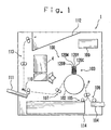
- Fig. 1 schematically shows an ink jet recording apparatus 1 according to one embodiment of the present invention.
- the ink jet recording apparatus 1 according to the present embodiment effects color printing on paper corresponding to a recording medium.
- the paper may be used, for example, a plain paper, a coated paper, an OHP sheet, etc.
- the print section 100 performs printing based on print data by means of the print unit 103 while being rotated at a predetermined speed in a state of bearing paper on the outer periphery of the drum 102.
- the print unit 103 includes four nozzle units 120C (Cyan), 120Y (Yellow), 120M (Magenta) and 120B (Black).
- the nozzle units 120C, 120Y, 120M and 120B are respectively provided with a plurality of the ink jet heads 2 to be described later.
- the print unit 103 is disposed on the upper side of the drum 102 in such a manner that nozzles included in the ink jet heads 2 to be described later are opposed to the drum 102 from above.
- the respective nozzle units 120C, 120Y, 120M and 120B are disposed in an arrangement of 120C (Cyan), 120Y (Yellow), 120M (Magenta) and 120B (Black) in order from the upstream side.
- the respective nozzle units 120C, 120Y, 120M and 120B are disposed such that the plurality of ink jet heads extend in an X-axis direction of the drum.
- the respective nozzle units 120C, 120Y, 120M and 120B are arranged in such a manner that the direction of an arrangement of the nozzles included in the ink jet heads 2 to be described later extends parallel to the direction of an axial center of the drum 102.
- the ink jet recording apparatus 1 is equipped with an ink supply mechanism 4 for supplying ink to the ink jet heads 2 (see Fig. 2) provided in the print unit 103.
- the ink supply mechanism 4 supplies ink of corresponding colors to the nozzle units 120C, 120Y, 120M and 120B respectively.
- the ink jet recording apparatus 1 is provided with a controller 109 for generally controlling respective portions that the ink jet recording apparatus 1 has (see Figs. 5 and 11).
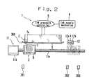
- Fig. 2 is a schematic diagram illustrating an ink jet recording apparatus of the present invention.
- the ink jet recording apparatus 1 includes an ink jet recording head 2 for delivering ink to an unillustrated recording medium, and maintenance means 3 for cleaning an ink jet recording head 2.
- the ink jet recording head 2 is provided with a plurality of pressure chambers for holding ink supplied by the ink supply mechanism 4 and performs printing according to changes in volumes of the pressure chambers.
- Each pressure chamber of the ink jet recording head 2 is formed by grooves defined in a substrate and for opening front and top face sides, a top plate for blocking the top face of each groove, and a nozzle plate 5 for blocking the front face of each groove.
- the substrate formed with the grooves is formed by bonding two piezoelectric members polarized in a board-thickness direction in such a manner that their polarized directions are opposite to each other.
- the grooves are formed by processing the substrate along a laminated direction of the piezoelectric members.
- the respective grooves are respectively partitioned in parallel by side walls placed between the respective grooves.
- An electrode is formed in an inner surface of each groove.
- the electrode can be formed using an electroless nickel plating method, for example.
- the substrate is provided with wiring patterns provided in continuation with the electrode.
- the top plate is formed with a common ink chamber which communicates with the respective pressure chambers, and an ink supply port for supplying ink to the common ink chamber.
- the ink supply mechanism 4 supplies ink stored or held in an ink tank to the ink supply port.
- a liquid type ink such as aqueous, oil, or ultra-violet cured one is used.
- the ink employed in the present embodiment contains pigment or dye or the like as a color material.
- the nozzle plate 5 is formed with a plurality of nozzles 10 (see Fig. 3) which extend therethrough in its plate-thickness direction.
- the respective nozzles 10 are respectively provided in association with the respective pressure chambers.
- the nozzle plate 5 is provided with an ink repellent layer having an ink repellent characteristic for repelling ink.
- the ink repellent layer includes peripheral surfaces of the nozzles 10 and is provided over the whole surface of the nozzle plate 5. It is thus possible to stabilize a delivery direct-advance property of ink droplets.
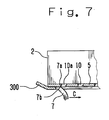
- the ink jet head 2 is provided with a protective member 300 for protecting the nozzle plate 5 outside the nozzle plate 5.
- the provision of the protective member 300 prevents the inability to maintain the basic characteristic of the head due to the occurrence of flaws and breakage in the nozzle plate 5.
- the protective member 300 is capable of preventing the occurrence of damage such as flaws in the nozzle plate 5 upon adjusting a gap between a print surface (paper) and the ink jet head 2.
- the protective member 300 is capable of fulfilling the function of protecting the nozzle plate 5 even against an external force that has the potential of being applied to the nozzle plate 5 upon transportation of the ink jet head 2, for example.
- the ink supply mechanism 4 is equipped with an ink tank for holding ink therein, a filter for removing foreign particles contained in the ink held in the ink tank, etc.
- the ink supplied by the ink supply mechanism 4 is controlled in its supply pressure by an ink pressure controller 6.
- the ink pressure controller 6 adjusts pressure of ink supplied to the ink jet recording head 2 with respect to the entirety of the ink jet recording head 2. It is thus possible to adjust the position of an ink level at each nozzle 10.
- the maintenance means 3 includes a wipe member 7 formed of an elastic material and a wipe support member 8 which supports the wipe member 7 and is movable in a nozzle arrangement direction along the nozzle plate 5.
- the wipe member 7 is shaped in a long form and wound in a roll fashion.
- a tip of the wipe member 7 serves as a wipe portion abutted against the nozzle plate.
- the wipe portion is provided with an edge portion 7a extending along the direction intersecting the direction of movement of the wipe support member 8.
- the wipe member 7 can be formed of a rubber member such as acrylonitrile-butadiene rubber (NBR), fluorine rubber (FPM) or the like.
- the wipe support member 8 includes a support structure 20 (see Fig. 5) for rotatably supporting the wipe member 7 about a winding axial center thereof at a fixed position in the wipe support member 8.
- the support structure 20 has a construction capable of making it possible to rotate the wipe member 7 and fixing its rotation.
- a mechanism as to support the wipe member 7 is realized by the wipe support member 8.
- various known technologies can be applied to the support structure 20 for rotatably and fixably holding a roll-shaped object, and the description thereof will be omitted herein.
- the wipe support member 8 normally supports the wipe member 7 in a state in which the rotation of the wipe member 7 is being fixed.
- the state in which the wipe support member 8 has fixed the rotation of the wipe member 7 in this way will be subsequently defined as a fixed support state.
- a fixed support state such a state that the tip of the wipe member 7 is brought into contact with or abutted against the nozzle plate 5 in the fixed support state, is defined as an abutted support state. This will be described in distinction from the simple fixed support state.
- the wipe support member 8 is provided so as to be capable of moving forward and backward alternately along the direction of the arrangement of the nozzles 10 as will be described later, the wipe support member 8 is on standby at home position except for the execution of a maintenance operation to be described later.
- the home position of the wipe support member 8 may be a position where the tip of the wipe member 7 is not brought into contact with the nozzle plate 5.
- a position that even though the wipe member 7 per se is located in a position opposite to the nozzle plate 5, the tip thereof is withdrawn from the nozzle plate 5 to be brought into contact with the protective member 300 may be defined as the home position of the wipe member 7.
- the wipe member 7 is brought into contact with the protective member 300 more outside the nozzle 10a used as an outermost portion as viewed in the direction of the arrangement of the nozzles 10.
- the distance as viewed in the direction of the arrangement of the nozzles 10 from the nozzle 10a to the position where the wipe member 7 and the protective member 300 are brought into contact with each other is expressed by P1
- the distance as viewed in the ink delivery direction from the nozzle plate 5 to the tip of the wipe member 7 is expressed by P2.
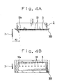
- the home position of the wipe support member 8 may be set to a position which is located more outside a nozzle 10a used as an outermost portion as viewed in the direction of an arrangement of nozzles 10 and which is opposite to a nozzle plate 5 as shown in Figs. 4A and 4B, for example.
- Fig. 4A the distance as viewed in the direction of the arrangement of the nozzles 10 from the position of support of a wipe member 7 by the wipe support member 8 to the wipe member 7 is expressed by P3.
- the distance P3 is set longer than the length from the nozzle 10a to the other end of a protective member 300 as viewed in the direction of the arrangement of the nozzles 10.
- the ink jet recording apparatus 1 is equipped with a wipe member home position sensor 301 whose output changes according to whether the wipe support member 8 is located in its home position.
- the wipe support member 8 is movable forward and backward alternately in a vertical direction as seen on the paper in Fig. 2 by the support structure 20.
- the wipe member 7 is abutted against the nozzle plate 5 only in the case where it moves in one direction (from the left to right direction in Fig. 2) toward the direction in which the wipe member is separated from its home position.
- the direction in which the wipe member proceeds from the home position to the right side in Fig. 2 is subsequently defined as a sweep direction.
- the wipe support member 8 When the position shown in Figs. 4A and 4B is assumed to be the home position of the wipe support member 8, the wipe support member 8 may be located in a position indicated by a solid line in Fig. 4A or may be located in a position indicated by a dotted line in Fig. 4A. In the present embodiment, the position indicated by the solid line in Fig. 4A is defined as the home position of the wipe support member 8.
- the wipe support member 8 supports the wipe member 7 so as to press an edge portion 7a against the nozzle plate 5 (see Fig. 7).
- the wipe support member 8 placed in the press support state elastically bends the tip of the wipe member 7 and urges the edge portion 7a toward the nozzle plate 5 under an elastic force of the wipe member 7 itself.
- the wipe member 7 is bent in such a manner that its tip is placed on the rear side with respect to the progress side (direction indicated by arrow c in Fig. 3) corresponding to the direction in which the wipe support member 8 is first moved when the wipe support member 8 is moved in a reciprocating manner by wipe member moving means 11 to be described later.
- the wipe support member 8 employed in the present embodiment serves as a cartridge and is provided detachably from a main body of the apparatus together with the wipe member 7.
- the wipe member 7 is supported detachably with respect to the wipe support member 8 and can be replaced with respect to the wipe support member 8.
- the wipe support member 8 is movable along the direction of the arrangement of the nozzles 10 by the wipe member moving means 11. While the description of a mechanism for moving the wipe support member 8 in the reciprocating manner is omitted because of the known technology, it can be realized by, for example, a shaft 11a extended out in the moving direction of the wipe support member 8, and a drive source 11b such as a motor for reciprocating the wipe support member along the shaft.
- the wipe member moving means 11 realizes a mechanism 11 for moving the mechanism 8 for supporting the wipe member 7 along the nozzles 10.
- the wipe member moving means 11 is driven upon the maintenance operation to be described later and reciprocates the wipe support member 8 along the direction (sweep direction) of the arrangement of the nozzles 10. Upon execution of the maintenance operation to be described later, the wipe member moving means 11 moves the wipe support member 8 in the sweep direction in a state in which the edge portion 7a of the wipe member 7 is abutted against the nozzle plate 5.
- a wipe member end position sensor 302 whose output changes depending on the presence or absence of the wipe support member 8 is provided at a return position of the movement of the wipe support member 8 in the sweep direction.
- the wipe member moving means 11 restores the wipe support member 8 to its home position according to a change in the output of the wipe member end position sensor 302 upon execution of the maintenance operation to be described later.
- the support structure 20 is driven upon restoring of the wipe support member 8 to the home position to separate the tip of the wipe member 7 and the nozzle plate 5 from each other upon returning of the wipe support member 8 to the home position.
- the wipe member 7 wound in the roll form is used as in the present embodiment, the wipe member 7 and the nozzle plate 5 can be spaced away from each other by rotating the wipe member 7 in its winding direction. Even in addition to it, however, there is considered, for example, a method of moving the wipe support member 8 per se downward to thereby separate the tip of the wipe member 7 and the nozzle plate 5 from each other.
- the timing for restoring the wipe support member 8 to the home position is determined, based on the change in the output from the wipe member end position sensor 302 is provided in the present embodiment, no limitation is imposed on it.
- the timing for restoring the wipe support member 8 to the home position may be determined by managing the distance of motion of the wipe support member 8 with respect to the distance as viewed in the direction of the arrangement of the nozzles 10.
- the maintenance means 3 is provided with a wipe member cutting mechanism 12 for cutting the tip of the wipe member 7.
- the wipe member cutting mechanism 12 includes a blade portion 12a used to cut the wipe member 7, and a receiving table 12b for supporting the wipe member 7 upon its cutting.
- the blade portion 12a is provided reciprocatingly in the direction to approach the receiving table 12b and detach therefrom. Upon cutting of the wipe member 7, the blade portion 12a is displaced in the direction to approach the receiving table 12b to thereby bring its tip into contact with the receiving table 12b.
- a moving trajectory of the blade portion 12a at this time is defined as a cut position X (indicated by a broken line in Fig. 1).
- the cut position X falls within a moving range of the wipe support member 8 as viewed in the moving direction of the wipe support member 8 and is provided at a position where the wipe member 7 is not abutted against the nozzle plate 5.
- the blade portion 12a is provided on the ink jet recording head 2 side rather than on the receiving table 12b side, in order to cut the wipe member 7 upon moving in the sweep direction.
- the ink jet recording apparatus 1 is provided with a wipe member cut position detecting sensor 303 whose output changes according to the presence or absence of the wipe member support member 8 at such a position of the wipe support member 8 as to locate the wipe member 7 in the cut position X as viewed in the moving direction of the wipe support member 8.
- the timing provided to bring out the wipe member 7 is measured according to the presence or absence of the change in the output from the wipe member cut position detecting sensor 303.
- the present invention is not limited to it.
- the timing provided to bring out the wipe member 7 may be measured by managing the distance of movement of the wipe support member 8 with respect to the distance as viewed in the direction of the arrangement of the nozzles 10.
- the wipe member home position sensor 301, the wipe member end position sensor 302 and the wipe member cut position detecting sensor 303 can respectively be realized by, for example, a photointerruptor or the like and are respectively configured so as to receive light emitted from a light-emitting element by means of a light-receiving element.
- the light-emitting element and the light-receiving element are placed in an opposing relation with a moving trajectory of the wipe support member 8 being interposed therebetween, and their outputs change according to the presence or absence of passage of the wipe support member 8 between the light-emitting element and the light-receiving element.
- the ink jet recording apparatus 1 has a control portion 150 in which various control keys or the like which accept operations made by an operator, are arranged (see Fig. 5).
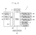
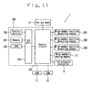
- Fig. 5 is a block diagram showing electrical connections between respective portions with which the ink jet recording apparatus 1 is equipped.
- the ink jet recording apparatus 1 has the controller 109 for driving and controlling the respective portions included in the ink jet recording apparatus 1.
- the controller 109 is configured by connecting a CPU 152 for executing various control programs to thereby drive and control the respective portions included in the ink jet recording apparatus 1, a ROM for storing the various control programs therein, a memory 151 which serves as a work area of the CPU, etc. via an I/O port 154.
- the wipe member home position sensor 301, wipe member end position sensor 302, and wipe member cut position detecting sensor 303 are connected to the I/O port 154 through a control circuit 153.
- the aforementioned ink pressure controller 6, wipe moving means 11, support structure 20 and ink jet head 2 are additionally connected to the control circuit 153.
- the controller 109 drives and controls the respective portions included in the ink jet recording apparatus 1 to thereby execute a print operation and a maintenance operation.
- the controller 109 performs the maintenance operation or the like, based on a signal outputted from the control portion 150 according to each key operation of the operator, for example.
- An area for storing various data or the like to which references are made upon execution of a maintenance operation and a switching operation to be described later, is ensured in the memory 151. For instance, the number of maintenance executions cumulated from the execution of the previous maintenance operation, and data about a maintenance non-execution time or the like counted since the execution of the previous maintenance are stored in the present area. Ascending data and descending data to which references are made upon upward and downward operations of the tip of the wipe member 7 by the support structure 20 and which are related to displacements, etc. are stored in the area. In addition to it, various counter areas used upon execution of the maintenance operation and the switching operation to be described later are ensured in the memory 151.
- a voltage is applied to an electrode corresponding to a pressure chamber intended for delivery of ink, based on print data upon a print operation.
- a pair of side walls in the pressure chamber to which the voltage is applied is deformed so as to temporarily expand the volume of the pressure chamber and shrink it.
- some of the ink absorbed into the pressure chamber are delivered from each nozzle 10 as ink droplets.
- the ink might remain around the nozzles 10 which have delivered the ink therethrough, upon such a print operation. Since such remaining ink flexes the direction of delivery of the ink and clogs up the nozzles 10 when dried/cured, to thereby lead to the occurrence of a failure in the delivery of the ink, there is a need to remove the remaining ink.
- the ink jet recording apparatus 1 removes ink and foreign particles remaining in the nozzle plate 5 according to the maintenance operation made by the maintenance means 3.
- the maintenance operation made by the maintenance means 3 will be explained below.
- the maintenance means 3 is on standby until the execution of the maintenance operation is declared. When it determines that the execution of the maintenance operation has been declared, the maintenance means 3 is driven and controlled by the controller 109 to perform the maintenance operation.
- the maintenance operation is carried out where the execution of the maintenance operation is declared by an operator's key operation or the like, for example.
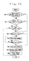
- Step S1 When it is determined that the execution of the maintenance operation has been declared (Y in Step S1) during standby of the declaration of the execution of the maintenance operation (N in Step S1), the support structure 20 is driven to rotate the wipe member 7 and elevate the wipe support member 8 (Step S2) until it is determined based on the ascending data stored in the memory 151 that the wipe support member 8 has ascended up to its upper limit (N in Step S3).
- Step S4 When it is determined based on the ascending data stored in the memory that the wipe support member 8 has ascended up to its upper limit (Y in Step S3), the wipe member moving means 11 is driven and controlled (Step S4) to move the wipe support member 8 from the left to the right in Fig. 2 until it is determined based on the change in the output from the wipe member end position sensor 302 that the wipe support member 8 has reached its end position (N in Step S5).
- the tip of the wipe member 7 is abutted against the nozzle plate 5 as shown in Fig. 7.
- the wipe support member 8 is moved in the sweep direction to thereby make it possible to move the wipe member 7 so as to rub against the nozzle plate 5. Consequently, the ink and foreign particles remaining around the nozzles 10 can be swept away from the nozzle plate 5.
- Step S5 When it is determined based on the change in the output from the wipe member end position sensor 302 that the wipe support member 8 has reached its end position (Y in Step S5), the driving of the wipe member moving means 11 is stopped (Step S6), and the up-down mechanism is driven to move the wipe support member 8 downward (Step S7) until it is determined based on the descending data stored in the memory that the wipe support member 8 has descended to its lower limit (N in Step S8).
- Step S9 the wipe member moving means 11 is driven in a reverse direction (Step S9) until it is determined based on the change in the output from the wipe member home position sensor 301 that the wipe support member 8 has been moved to its home position (N in Step S10).
- Step S10 When it is determined based on the change in the output from the wipe member home position sensor 301 that the wipe support member 8 has been moved to the home position (Y in Step S10), the driving of the wipe member moving means 11 is stopped (Step S11) and a counter provided for the memory is incremented (Step S12). It is then determined whether the incremented count has reached the preset number of times that maintenance is performed (Step S13).
- Step S13 When it is determined that the incremented count does not reach the preset number of times that the maintenance is performed (N in Step S13), the processing is completed as it is. When it is determined that the incremented count has reached the preset number of times that the maintenance is executed (Y in Step S13), execution of a switching operation to be described later is declared (Step S14).
- the above operation flowchart was shown in Fig. 6.
- the ink and foreign particles removed from the nozzle plate 5 by sweeping are adhered to the wipe member 7 and increase with repetition of the maintenance operation.
- sweeping capability is degraded and the foreign particles are transferred to the nozzle plate 5, whereby a print failure might be brought about.
- Such degradation of the sweeping capability is brought to the fore as abrasion of the wipe member 7 makes progress.
- the capability of sweeping by the maintenance means 3 can be maintained by carrying out a switching operation to be described later.
- the switching operation of the maintenance means 3 will be described below.
- the maintenance means 3 is on standby until the execution of the switching operation is declared. When it determines that the execution of the switching operation has been declared, the maintenance means 3 is driven and controlled by the controller 109 to perform the switching operation.
- the switching operation is executed with timing at which a predetermined number of maintenance operations are performed, timing at which no maintenance operation is executed, or timing at which execution is instructed by an operator's key operation or the like.
- the execution of a cutting operation is declared upon the above-described maintenance operation where the predetermined number of maintenance operations are performed. Therefore, the cutting operation is executed with timing at which the execution of the cutting operation is declared.
- the ink jet recording apparatus 1 takes such a configuration as to count a time elapsed since the completion of the maintenance operation for each completion of the aforementioned maintenance operation and declare the execution of the cutting operation where the counted time is over a predetermined time. Incidentally, when a print operation or a maintenance operation is newly executed before the elapse of a predetermined time, the counted elapsed time is cleared.
- the wipe member moving means 11 moves the wipe member in a cut position X direction (Step S23) until it is determined based on an output value from the wipe member cut position detecting sensor 303 that the wipe support member 8 has been moved to the cut position X (N in Step S24).
- Step S24 When it is determined based on the output value from the wipe member cut position detecting sensor 303 that the wipe support member 8 has been moved to the cut position X (Y in Step S24), the wipe member moving means 11 is stopped (Step S25), and the support structure 20 is driven to rotate the wipe member 7, thereby paying or bringing out the wipe member 7 to such an extent that the tip of the wipe member 7 extends beyond the cut position X by the wipe member cutting mechanism 12 (Step S26).
- Step S27 wipe portion switching means with respect to the nozzle plate 5 is realized.
- the wipe member 7 After its cutting, the wipe member 7 is moved down such that the height of the tip portion of the wipe member 7 becomes lower than the nozzle plate 5 (Step S28).
- the wipe member moving means 11 is driven (Step S29) until it is determined based on a change in the output from the wipe member home position sensor 301 that the wipe support member 8 has been moved to its home position (N in Step S30).
- Step S30 When it is determined based on the change in the output from the wipe member home position sensor 301 that the wipe support member 8 has been moved to the home position (Y in Step S30), the driving of the wipe member moving means 11 is stopped (Step S31), and the counter and timer are cleared (Step S32).
- Step S31 When it is determined based on the change in the output from the wipe member home position sensor 301 that the wipe support member 8 has been moved to the home position (Y in Step S30), the driving of the wipe member moving means 11 is stopped (Step S31), and the counter and timer are cleared (Step S32).
- the above-described operation flowchart was shown in Fig. 8.
- the tip of the wipe member 7 at which sweeping capability is degraded due to abrasion and adhesion of foreign matters or particles, is removed and hence a new tip is produced. Therefore, the capability of sweeping by the maintenance means 3 can be restored in a manner similar to the initial state. According to the present embodiment, satisfactory capability of sweeping by the maintenance means 3 can be ensured over a long period with suitable execution of the switching operation.
- the wipe member 7 is not cut more than necessary each time the maintenance operation is done, for example. Consequently, the capability of sweeping by the maintenance means 3 can be maintained over a longer period.
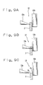
- the wipe member 7 is formed of the elastic material, a portion thereof brought into contact with the blade portion 12a is pressed by its own elasticity and thereby brought into an extended (recessed) state in a cutting initial stage at which the tip of the blade portion 12a is brought into contact with the wipe member 7 upon cutting (see Fig. 9A). Then, its extension is cut when it goes beyond a limit based on its own elasticity (see Fig. 9B).
- the shape of the tip of the post-cut wipe member 7 is brought to such a state that the receiving table 12b side is made squarish and the blade portion side taken as the cutting early side is assumed to be slightly roundish, as shown in Fig. 9C.
- a squarish portion is used as an edge portion 7a and the slightly roundish portion is used as a corner arcuate portion 7b
- the contact of the edge portion 7a with the nozzle plate 5 rather than the contact of the corner arcuate portion 7b with the nozzle plate 5 brings about a large effect upon the maintenance operation using the wipe member 7 having such a tip shape in terms of removal of the remaining inks.
- the edge portion 7a can always be abutted against the nozzle plate 5 upon the maintenance operation. It is thus possible to satisfactorily maintain the capability of sweeping by the maintenance means 3.
- the sweeping direction is set so as to extend from the left to right in the present embodiment, no limitation is imposed on it.
- the sweeping direction may be set to extend from the right to left in Fig. 2, for example. Since, in this case, the direction of the movement of the blade portion 12a at its cutting is set as the sweeping direction in the wipe member cutting mechanism 12, the blade portion 12a is disposed so as to be located in the direction to detach from the nozzle plate 5 rather than from the receiving table 12b according to the direction of sweeping by the wipe member 7.
- the wipe support member 8 can be detached from the main body of the apparatus together with the wipe member 7, the cartridge portion can be replaced by another where the wipe member 7 is used up to a position where it can be paid out.
- satisfactory capability of sweeping by the maintenance means 3 can be ensured over a longer period.
- the wipe member 7 in the maintenance means 3 is not necessarily limited to the above-described shape wound in the roll form.
- the maintenance means 3 having such a construction as shown in Fig. 10, for example, may be adopted.
- the maintenance means 3 shown in Fig. 10 is provided with a plurality of wipe members 7 each formed of an elastic body in a plate form. Tips of the respective wipe members 7 serve as wipe portions respectively.
- the wipe portions include edge portions 7a extending along the direction intersecting the direction of movement of a wipe support member 8.
- the respective wipe members 7 are held or accommodated within a wipe storage box 13 in a state in which they are laminated along the direction of the movement of the wipe support member 8.
- the wipe storage box 13 is supported so as to be movable along the direction of lamination of the wipe members 7 with respect to the wipe support member 8.
- the wipe storage box 13 is urged from the left to right in Fig. 10 by a spring 14 and thereby brought into contact with a cam 15 provided in the wipe support member 8 in Fig. 10.
- the cam 15 is rotatably driven by a controller 109.
- a hole 13b for allowing a pressing member 16 provided for the wipe support member 8 to be inserted is provided at a bottom face 13a of the wipe storage box 13.
- the hole 13b is formed such that the respective wipe members can be pressed from below by means of the pressing member 16.
- the respective wipe members 7 are moved along the direction of their lamination with respect to the pressing member 16 to thereby make it possible to replace the corresponding wipe member 7 abutted against the nozzle plate 5.
- the pressing members 16 may be respectively provided on the sides below the respective wipe members 7, for example.
- the pressing member 16 is provided so as to be capable of appearing in a vertical direction in Fig. 10 and has such a configuration as to be capable of being inserted into the hole 13b defined in the wipe storage box 13 and being pulled out of the bottom face 13a side.
- the pressing member 16 is coupled to a cam 17 provided rotatably with respect to the wipe support member 8.
- the cam 17 is rotatably driven by the controller 109 to allow the pressing member 16 to appear.
- Such a pressing member 16 is capable of pressing the tip of the selectively-extruded wipe member 7 so as to abut against the nozzle plate 5.
- the positions of the wipe members 7 stored in the wipe storage box 13 are defined as their storage positions, and the position of the corresponding wipe member 7 which is extruded from the wipe storage box 13 by the pressing member 16 and abutted against the nozzle plate 5, is defined as a press position.
- the wipe storage box 13, hole 13b, spring 14, cam 15, pressing member 16, cam 17 and wipe support member 8 realize a mechanism for supporting the wipe member 7.
- the wipe storage box 13 serves as a cartridge and is supported detachably with respect to the wipe support member 8.
- the wipe storage box 13 is detachable in the present embodiment, the present invention is not limited to it.
- the wipe support member 8 may be detachably provided in a manner similar to the above-described embodiment.
- Step S40 When it is determined that the execution of the switching operation has been declared due to the aforementioned various factors (Y in Step S40, Y in Step S41 or Y in Step S42) during standby of the declaration of execution of the switching operation (N in Step S40, N in Step S41 and N in Step S42) in a manner similar to Fig. 8, it is determined, based on a change in the output from a wipe member home position sensor 301, whether the wipe support member 8 is placed in its home position (Step S43) .
- wipe member moving means 11 is driven (Step S44) until it is determined based on the change in the output from the wipe member home position sensor 301 that the wipe support member 8 has been moved to the home position (N in Step S45).
- Step S46 When it is determined based on the change in the output from the wipe member home position sensor 301 that the wipe support member 8 has been moved to the home position (Y in Step S45), the driving of the wipe member moving means 11 is stopped (Step S46) and the corresponding wipe member 7 is replaced by another (Step S47).
- Step S47 the cam is rotated to pull down the pressing member 16, and the cam 15 is rotated by a predetermined angle. Consequently, the wipe member 7 abutted against the nozzle plate 5 at its pressed position by the pressing member 16 is restored to its corresponding storage position. Further, the spring 14 is compressed so that the wipe storage box is moved from right to left in Fig. 10.
- the turning angle of the cam 15 is defined in advance to thereby make it possible to displace the position of the wipe storage box 13 with respect to the wipe support member 8 by the thickness of one sheet of wipe member 7.
- the pressing member 16 is displaced to a press position again.
- the wipe member 7 adjacent to the wipe member 7 just-stored in the storage position is extruded and located in a press position, and then pressed so as to abut against the nozzle plate 5.
- means for selecting the positions of abutment of the wipe members 7 against the nozzle plate 5 is realized.
- the capability of sweeping by the maintenance means 3 can be restored in a manner similar to the initial state with no cumbersome wipe-member replacement work. Since the maintenance means 3 is provided with the plurality of wipe members 7, the capability of sweeping by the maintenance means 3 can be ensured over a long period.
- the cartridge portion can be replaced by another where all the wipe members 7 are used up. It is thus possible to ensure satisfactory capability of sweeping by the maintenance means 3 over a longer period.
- the maintenance means 3 for cleaning the ink jet recording head 2 comprises the wipe members 7 each formed of the elastic material and holding the plurality of wipe portions so as to be capable of appearing, the mechanism 8 for supporting the corresponding wipe member 7 so as to bring one wipe portion into contact with the nozzle plate 5 in which the plurality of nozzles 10 communicating with each pressure chamber for holding ink are arranged, the mechanism 11 for moving the mechanism 8 supporting the wipe members 7 along the nozzles 10, and the means for performing switching between the wipe portions abutted against the nozzle plate 5.
- the corresponding wipe member 7 abutted against the nozzle plate 5 is moved along the nozzles 10 to remove ink and foreign particles remaining around the nozzles 10, and the position of abutment of the wipe member 7 against the nozzle plate 5 is suitably selected, whereby satisfactory sweeping capability of the wipe member 7 can be maintained without providing a mechanism for cleaning each wipe member 7, and performing the work of replacing the wipe member 7 with another.
- the ink jet recording apparatus 1 of the present invention which is equipped with such a maintenance means 3 for cleaning the ink jet recording head 2, satisfactory delivery performance at print can be maintained.
- each of the wipe portions has the edge portion 7a extending along the direction intersecting its moving direction, and the mechanism 8 for supporting the wipe member 7 supports the wipe member 7 so as to abut the edge portion 7a against the nozzle plate 5. It is therefore possible to enhance capability of sweeping by the wipe member 7 without complicating a configuration.
- the ink jet recording apparatus 1 of the present invention which is equipped with such a maintenance means 3 for cleaning the ink jet recording head 2, satisfactory delivery performance at print can be maintained, and reliability at print can be enhanced.
- the mechanism 8 for supporting each wipe member 7 supports the wipe member 7 in such a manner that the edge portion 7a is urged toward the nozzle plate 5 by the elastic force of the wipe member 7. It is therefore possible to further enhance sweeping capability of the wipe member 7 without complicating a configuration.
- the ink jet recording apparatus 1 of the present invention which is provided with such a maintenance means 3 for cleaning the ink jet recording head 2, satisfactory delivery performance at print can be assuredly maintained, and reliability at print can be enhanced.
- the wipe member 7 is wound in the roll form, the mechanism 8 for supporting the wipe member 7 abuts the tip of the wipe member 7 against the nozzle plate 5 and supports the tip of the wipe member 7 so as to be capable of paying out the tip thereof, and the means for performing switching of the wipe portion cuts the tip of the wipe member 7 paid or brought out from the mechanism for supporting the wipe member 7, by means of the wipe member cutting mechanism 12 to thereby select the corresponding wipe portion. Therefore, the wipe member 7 having high sweeping capability can be always abutted against the nozzle plate 5, and satisfactory sweeping capability of the wipe member 7 can be maintained over a long period.
- the ink jet recording apparatus 1 of the present invention which is equipped with such a maintenance means 3 for cleaning the ink jet recording head 2, satisfactory delivery performance at print can be maintained over a long period.
- the mechanism 8 for supporting each wipe member 7 supports the wipe member 7 such that its wipe portion is abutted against the nozzle plate 5 upon only its movement in one direction
- the wipe member cutting mechanism 12 includes the single blade portion 12a for cutting the wipe member 7 upon moving the wipe portion in the direction identical to the direction of movement of the wipe member 7 abutted against the nozzle plate 5. Therefore, the edge portion 7a can be abutted against the nozzle plate 5 without effecting particular processing on the post-cut wipe member 7, and satisfactory sweeping capability can be provided.
- the ink jet recording apparatus 1 of the present invention which is equipped with such a maintenance means 3 for cleaning the ink jet recording head 2, satisfactory delivery performance at print can be maintained over a long period.
- the means for selecting the wipe members respectively having the wipe portions and provided in plural form replaces the wipe member 7 whose wipe portion is abutted against the nozzle plate 5 with another to thereby select the corresponding wipe portion. It is therefore possible to always abut the wipe member 7 having high sweeping capability against the nozzle plate 5 and maintain satisfactory sweeping capability of the wipe member 7 over a long period.
- the ink jet recording apparatus 1 of the present invention which is equipped with such a maintenance means 3 for cleaning the ink jet recording head 2, satisfactory delivery performance at print can be maintained over a long period.
- the means for selecting the abutment position of each wipe member 7 performs switching of the abutment position each time the wipe member 7 is moved a predetermined number of times along the nozzles 10. Therefore, for example, the timing provided to switch the abutment position is suitably set to thereby make it possible to sweep the nozzle plate 5 according to its use state without needlessly selecting the abutment position, whereby satisfactory sweeping capability of the wipe member 7 can be maintained over a longer period.
- the ink jet recording apparatus 1 of the present invention which is equipped with such a maintenance means 3 for cleaning the ink jet recording head 2, satisfactory sweeping capability of the wipe member 7 can be maintained over a longer period.
- the mechanism 8 for supporting each wipe member 7 is detachable in a state of having supported the wipe member 7. Therefore, the mechanism 8 for supporting the wipe member 7 is detached from the main body of the apparatus, so that only the mechanism for supporting the wipe member 7 or the wipe member 7 can be replaced by another, and hence satisfactory sweeping capability of the wipe member 7 can be maintained over a longer period.
- the ink jet recording apparatus 1 of the present invention which is equipped with such a maintenance means 3 for cleaning the ink jet recording head 2, satisfactory sweeping capability of the wipe member 7 can be maintained over a longer period.
Landscapes
- Ink Jet (AREA)
Applications Claiming Priority (2)
| Application Number | Priority Date | Filing Date | Title |
|---|---|---|---|
| US396301 | 2003-03-25 | ||
| US10/396,301 US6866362B2 (en) | 2003-03-25 | 2003-03-25 | Ink Jet recording apparatus having maintenance means for cleaning an ink jet recording head |
Publications (2)
| Publication Number | Publication Date |
|---|---|
| EP1464498A2 true EP1464498A2 (fr) | 2004-10-06 |
| EP1464498A3 EP1464498A3 (fr) | 2005-08-24 |
Family
ID=32850534
Family Applications (1)
| Application Number | Title | Priority Date | Filing Date |
|---|---|---|---|
| EP04251171A Withdrawn EP1464498A3 (fr) | 2003-03-25 | 2004-03-01 | Imprimante à jet d'encre avec moyen de maintenance pour une tête à jet d'encre |
Country Status (3)
| Country | Link |
|---|---|
| US (1) | US6866362B2 (fr) |
| EP (1) | EP1464498A3 (fr) |
| JP (1) | JP2004291619A (fr) |
Cited By (1)
| Publication number | Priority date | Publication date | Assignee | Title |
|---|---|---|---|---|
| EP2418087A1 (fr) * | 2010-08-10 | 2012-02-15 | Miyakoshi Printing Machinery Co., Ltd. | Procédé d'essuyage de tête de ligne |
Families Citing this family (20)
| Publication number | Priority date | Publication date | Assignee | Title |
|---|---|---|---|---|
| US20040189735A1 (en) * | 2003-03-24 | 2004-09-30 | Toshiba Tec Kabushika Kaisha | Ink jet head cleaning apparatus and ink jet recording apparatus |
| US20040257396A1 (en) * | 2003-06-19 | 2004-12-23 | Toshiba Tec Kabushiki Kaisha | Ink jet head cleaning apparatus and ink jet recording apparatus |
| US7044580B2 (en) * | 2003-11-18 | 2006-05-16 | Toshiba Tec Kabushiki Kaisha | Ink jet recording head maintenance apparatus and ink jet recording apparatus |
| JP4049105B2 (ja) * | 2004-02-24 | 2008-02-20 | セイコーエプソン株式会社 | ワイピング装置および液滴吐出装置、並びに電気光学装置、電気光学装置の製造方法および電子機器 |
| KR100727971B1 (ko) * | 2005-09-01 | 2007-06-14 | 삼성전자주식회사 | 와이퍼, 클리닝 장치, 및 이를 구비하는 잉크젯화상형성장치 |
| US7648219B2 (en) * | 2005-09-21 | 2010-01-19 | Brother Kogyo Kabushiki Kaisha | Liquid-droplet jetting apparatus having a movable body for detecting and purging abnormal nozzles |
| JP4888061B2 (ja) * | 2005-11-08 | 2012-02-29 | ブラザー工業株式会社 | インクジェット記録装置 |
| US7563172B2 (en) * | 2006-02-08 | 2009-07-21 | Peter Mansfield | Interchangeable putter system |
| JP4329846B2 (ja) * | 2007-06-07 | 2009-09-09 | セイコーエプソン株式会社 | ギャップ調整装置及び画像形成装置 |
| US8118086B2 (en) * | 2009-06-16 | 2012-02-21 | Uop Llc | Efficient self cooling heat exchanger |
| JP5707354B2 (ja) | 2012-03-12 | 2015-04-30 | 東芝テック株式会社 | 画像形成装置 |
| JP5659179B2 (ja) | 2012-03-16 | 2015-01-28 | 東芝テック株式会社 | 画像形成装置 |
| JP2013212652A (ja) * | 2012-04-03 | 2013-10-17 | Toshiba Tec Corp | インクジェット記録装置 |
| JP6122124B2 (ja) * | 2012-09-20 | 2017-04-26 | ヒューレット−パッカード デベロップメント カンパニー エル.ピー.Hewlett‐Packard Development Company, L.P. | 印刷システムのサービス |
| JP6241050B2 (ja) * | 2013-03-21 | 2017-12-06 | ブラザー工業株式会社 | 液体吐出装置 |
| DE102013217421B4 (de) | 2013-08-22 | 2018-09-06 | Atlantic Zeiser Gmbh | Vorrichtung zum Reinigen von Druckern und Drucker mit einer solchen Vorrichtung |
| JP6350792B2 (ja) * | 2013-12-09 | 2018-07-04 | セイコーエプソン株式会社 | 液体噴射装置及び液体噴射ヘッドユニット |
| JP6521229B2 (ja) | 2015-03-20 | 2019-05-29 | セイコーエプソン株式会社 | 液体噴射装置 |
| JP7604958B2 (ja) * | 2021-03-10 | 2024-12-24 | セイコーエプソン株式会社 | 払拭モジュール、吐出モジュール、液体吐出装置および払拭モジュールの払拭方法 |
| CN113399331A (zh) * | 2021-06-09 | 2021-09-17 | 安徽强邦新材料股份有限公司 | 一种ctp版生产用铝版基的除油装置及除油方法 |
Family Cites Families (30)
| Publication number | Priority date | Publication date | Assignee | Title |
|---|---|---|---|---|
| US600792A (en) * | 1898-03-15 | Vapor | ||
| US4223322A (en) * | 1977-12-08 | 1980-09-16 | Olympia Werke Ag | Maintaining the nozzle surface of an ink writing head |
| JPS5675867A (en) | 1979-11-22 | 1981-06-23 | Seiko Epson Corp | Ink jet recorder |
| JP2614207B2 (ja) | 1985-10-30 | 1997-05-28 | キヤノン 株式会社 | インクジエツト記録装置 |
| JPS62251145A (ja) * | 1986-04-25 | 1987-10-31 | Canon Inc | インクジエツト記録装置 |
| JPH0295862A (ja) | 1988-10-03 | 1990-04-06 | Canon Inc | 記録ヘッドのワイピング方法 |
| JPH02179757A (ja) | 1988-12-30 | 1990-07-12 | Canon Inc | 画像記録装置 |
| JPH0347754A (ja) | 1989-04-26 | 1991-02-28 | Canon Inc | インクジェット記録装置 |
| ATE139941T1 (de) | 1990-02-26 | 1996-07-15 | Canon Kk | Tintenstrahlaufzeichnungsgerät und verfahren zum reinigen des aufzeichnungskopfes |
| US5103244A (en) * | 1990-07-05 | 1992-04-07 | Hewlett-Packard Company | Method and apparatus for cleaning ink-jet printheads |
| JP3161050B2 (ja) | 1991-06-12 | 2001-04-25 | 富士ゼロックス株式会社 | インクジェットヘッドのメンテナンス装置 |
| JP2834949B2 (ja) | 1991-09-11 | 1998-12-14 | キヤノン株式会社 | 改善されたインクジェットヘッド用クリーニング部材及び該クリーニング部材を備えたインクジェット装置 |
| JPH05220970A (ja) | 1992-02-17 | 1993-08-31 | Fuji Xerox Co Ltd | 印字ヘッドおよびそのメンテナンス機構 |
| JP3070639B2 (ja) | 1992-08-26 | 2000-07-31 | セイコーエプソン株式会社 | カラーインクジェット記録装置 |
| JP3065818B2 (ja) | 1992-10-26 | 2000-07-17 | キヤノン株式会社 | インクジェット記録装置 |
| US6000792A (en) | 1992-09-02 | 1999-12-14 | Canon Kabushiki Kaisha | Ink jet apparatus provided with an improved recovery mechanism |
| US5612722A (en) * | 1993-10-26 | 1997-03-18 | Lexmark International, Inc. | Ink jet printhead wiper having side surfaces intersecting a top surface at acute angles to form wiping edges and a slat centered in a bottom surface |
| US5589861A (en) * | 1994-05-31 | 1996-12-31 | Hewlett-Packard Company | Cleaner cartridge for an inkjet printing mechanism |
| JPH0976517A (ja) | 1995-09-14 | 1997-03-25 | Brother Ind Ltd | インクジェット式記録ヘッドのクリーニング装置 |
| JPH106516A (ja) * | 1996-06-25 | 1998-01-13 | Oki Data:Kk | インクジェットプリンタ |
| JP3329367B2 (ja) | 1996-10-21 | 2002-09-30 | セイコーエプソン株式会社 | インクジェット式記録装置 |
| US6151044A (en) * | 1997-10-29 | 2000-11-21 | Hewlett-Packard Company | Hide-away wiper cleaner for inkjet printheads |
| JP2000103072A (ja) | 1998-09-29 | 2000-04-11 | Canon Inc | インクジェット記録装置用の回復装置 |
| JP3473680B2 (ja) | 1998-10-29 | 2003-12-08 | セイコーエプソン株式会社 | インクジェット式記録装置 |
| JP3453531B2 (ja) | 1998-12-15 | 2003-10-06 | キヤノン株式会社 | インクジェット記録装置 |
| JP2000280494A (ja) | 1999-03-31 | 2000-10-10 | Copyer Co Ltd | インクジェット記録装置 |
| JP2001024248A (ja) * | 1999-07-07 | 2001-01-26 | Samsung Electro Mech Co Ltd | 低温焼成法による多層圧電/電歪セラミックアクチュエータの製造方法及びその方法によって製造された多層圧電/電歪セラミックアクチュエータ |
| JP2001219567A (ja) | 2000-02-08 | 2001-08-14 | Seiko Epson Corp | インクジェット式記録装置 |
| JP2001260368A (ja) | 2000-03-16 | 2001-09-25 | Konica Corp | インクジェット式記録ヘッドを用いる画像形成装置および画像形成方法 |
| JP4850369B2 (ja) | 2001-01-22 | 2012-01-11 | キヤノン株式会社 | インクジェット記録装置 |
-
2003
- 2003-03-25 US US10/396,301 patent/US6866362B2/en not_active Expired - Lifetime
- 2003-10-31 JP JP2003372383A patent/JP2004291619A/ja not_active Withdrawn
-
2004
- 2004-03-01 EP EP04251171A patent/EP1464498A3/fr not_active Withdrawn
Cited By (1)
| Publication number | Priority date | Publication date | Assignee | Title |
|---|---|---|---|---|
| EP2418087A1 (fr) * | 2010-08-10 | 2012-02-15 | Miyakoshi Printing Machinery Co., Ltd. | Procédé d'essuyage de tête de ligne |
Also Published As
| Publication number | Publication date |
|---|---|
| JP2004291619A (ja) | 2004-10-21 |
| US6866362B2 (en) | 2005-03-15 |
| US20040189741A1 (en) | 2004-09-30 |
| EP1464498A3 (fr) | 2005-08-24 |
Similar Documents
| Publication | Publication Date | Title |
|---|---|---|
| US6866362B2 (en) | Ink Jet recording apparatus having maintenance means for cleaning an ink jet recording head | |
| US7568782B2 (en) | Liquid ejection apparatus and image forming apparatus | |
| US6631974B2 (en) | Ink jet recording apparatus having wiping mechanism | |
| EP1462260B1 (fr) | Dispositif de formation d'image et méthode de restoration d'éjection de tête d'impression | |
| JP6682376B2 (ja) | インクジェット式記録装置 | |
| JP4508131B2 (ja) | インクジェットプリンタ | |
| KR101445427B1 (ko) | 기록 장치 | |
| US7044580B2 (en) | Ink jet recording head maintenance apparatus and ink jet recording apparatus | |
| JP3925729B2 (ja) | 画像形成装置 | |
| JP2016083877A (ja) | 印刷装置 | |
| US7188927B2 (en) | Printhead wiper cleaning mechanism for an imaging apparatus | |
| EP1488929A1 (fr) | Dispositif pour nettoyer une tête à jet d'encre et appareil d'enregistrement à jet d'encre | |
| JPH09234879A (ja) | インクジェットプリンタ | |
| JP5500083B2 (ja) | 液体吐出装置、制御装置、及び、プログラム | |
| JP5262365B2 (ja) | 液体吐出記録装置及びインクジェット記録装置 | |
| JPH0924625A (ja) | インクジェット記録装置 | |
| JP6370213B2 (ja) | 印刷装置および印刷装置のクリーニング方法 | |
| JP2004074590A (ja) | インクジェット記録装置 | |
| JP4635794B2 (ja) | インクジェット記録装置 | |
| JP2019130679A (ja) | 液体吐出ヘッドの洗浄装置及び液体を吐出する装置 | |
| US20090073220A1 (en) | Bidirectional printhead maintenance systems, methods and apparatus | |
| JP4569808B2 (ja) | プリントヘッド管理装置 | |
| JP2015171821A (ja) | 記録装置 | |
| JP2005035251A (ja) | インクジェット記録装置 | |
| JP2008221525A (ja) | 液体噴射装置、画像記録装置、および、画像記録装置の制御方法 |
Legal Events
| Date | Code | Title | Description |
|---|---|---|---|
| PUAI | Public reference made under article 153(3) epc to a published international application that has entered the european phase |
Free format text: ORIGINAL CODE: 0009012 |
|
| 17P | Request for examination filed |
Effective date: 20040324 |
|
| AK | Designated contracting states |
Kind code of ref document: A2 Designated state(s): AT BE BG CH CY CZ DE DK EE ES FI FR GB GR HU IE IT LI LU MC NL PL PT RO SE SI SK TR |
|
| AX | Request for extension of the european patent |
Extension state: AL LT LV MK |
|
| PUAL | Search report despatched |
Free format text: ORIGINAL CODE: 0009013 |
|
| AK | Designated contracting states |
Kind code of ref document: A3 Designated state(s): AT BE BG CH CY CZ DE DK EE ES FI FR GB GR HU IE IT LI LU MC NL PL PT RO SE SI SK TR |
|
| AX | Request for extension of the european patent |
Extension state: AL LT LV MK |
|
| AKX | Designation fees paid |
Designated state(s): DE FR GB |
|
| 17Q | First examination report despatched |
Effective date: 20070115 |
|
| STAA | Information on the status of an ep patent application or granted ep patent |
Free format text: STATUS: THE APPLICATION IS DEEMED TO BE WITHDRAWN |
|
| 18D | Application deemed to be withdrawn |
Effective date: 20091001 |