EP1465268A2 - Electrode et son utilisation dans une batterie - Google Patents
Electrode et son utilisation dans une batterie Download PDFInfo
- Publication number
- EP1465268A2 EP1465268A2 EP04007960A EP04007960A EP1465268A2 EP 1465268 A2 EP1465268 A2 EP 1465268A2 EP 04007960 A EP04007960 A EP 04007960A EP 04007960 A EP04007960 A EP 04007960A EP 1465268 A2 EP1465268 A2 EP 1465268A2
- Authority
- EP
- European Patent Office
- Prior art keywords
- active material
- material layer
- thin film
- current collector
- film layer
- Prior art date
- Legal status (The legal status is an assumption and is not a legal conclusion. Google has not performed a legal analysis and makes no representation as to the accuracy of the status listed.)
- Withdrawn
Links
Images


Classifications
-
- A—HUMAN NECESSITIES
- A01—AGRICULTURE; FORESTRY; ANIMAL HUSBANDRY; HUNTING; TRAPPING; FISHING
- A01G—HORTICULTURE; CULTIVATION OF VEGETABLES, FLOWERS, RICE, FRUIT, VINES, HOPS OR SEAWEED; FORESTRY; WATERING
- A01G9/00—Cultivation in receptacles, forcing-frames or greenhouses; Edging for beds, lawn or the like
- A01G9/02—Receptacles, e.g. flower-pots or boxes; Glasses for cultivating flowers
- A01G9/022—Pots for vertical horticulture
- A01G9/023—Multi-tiered planters
-
- H—ELECTRICITY
- H01—ELECTRIC ELEMENTS
- H01M—PROCESSES OR MEANS, e.g. BATTERIES, FOR THE DIRECT CONVERSION OF CHEMICAL ENERGY INTO ELECTRICAL ENERGY
- H01M4/00—Electrodes
- H01M4/02—Electrodes composed of, or comprising, active material
- H01M4/64—Carriers or collectors
- H01M4/66—Selection of materials
- H01M4/661—Metal or alloys, e.g. alloy coatings
-
- H—ELECTRICITY
- H01—ELECTRIC ELEMENTS
- H01M—PROCESSES OR MEANS, e.g. BATTERIES, FOR THE DIRECT CONVERSION OF CHEMICAL ENERGY INTO ELECTRICAL ENERGY
- H01M4/00—Electrodes
- H01M4/02—Electrodes composed of, or comprising, active material
- H01M4/13—Electrodes for accumulators with non-aqueous electrolyte, e.g. for lithium-accumulators; Processes of manufacture thereof
- H01M4/134—Electrodes based on metals, Si or alloys
-
- H—ELECTRICITY
- H01—ELECTRIC ELEMENTS
- H01M—PROCESSES OR MEANS, e.g. BATTERIES, FOR THE DIRECT CONVERSION OF CHEMICAL ENERGY INTO ELECTRICAL ENERGY
- H01M4/00—Electrodes
- H01M4/02—Electrodes composed of, or comprising, active material
- H01M4/13—Electrodes for accumulators with non-aqueous electrolyte, e.g. for lithium-accumulators; Processes of manufacture thereof
- H01M4/139—Processes of manufacture
- H01M4/1395—Processes of manufacture of electrodes based on metals, Si or alloys
-
- H—ELECTRICITY
- H01—ELECTRIC ELEMENTS
- H01M—PROCESSES OR MEANS, e.g. BATTERIES, FOR THE DIRECT CONVERSION OF CHEMICAL ENERGY INTO ELECTRICAL ENERGY
- H01M4/00—Electrodes
- H01M4/02—Electrodes composed of, or comprising, active material
- H01M4/36—Selection of substances as active materials, active masses, active liquids
- H01M4/362—Composites
- H01M4/366—Composites as layered products
-
- H—ELECTRICITY
- H01—ELECTRIC ELEMENTS
- H01M—PROCESSES OR MEANS, e.g. BATTERIES, FOR THE DIRECT CONVERSION OF CHEMICAL ENERGY INTO ELECTRICAL ENERGY
- H01M4/00—Electrodes
- H01M4/02—Electrodes composed of, or comprising, active material
- H01M4/36—Selection of substances as active materials, active masses, active liquids
- H01M4/38—Selection of substances as active materials, active masses, active liquids of elements or alloys
-
- H—ELECTRICITY
- H01—ELECTRIC ELEMENTS
- H01M—PROCESSES OR MEANS, e.g. BATTERIES, FOR THE DIRECT CONVERSION OF CHEMICAL ENERGY INTO ELECTRICAL ENERGY
- H01M4/00—Electrodes
- H01M4/02—Electrodes composed of, or comprising, active material
- H01M4/36—Selection of substances as active materials, active masses, active liquids
- H01M4/38—Selection of substances as active materials, active masses, active liquids of elements or alloys
- H01M4/386—Silicon or alloys based on silicon
-
- H—ELECTRICITY
- H01—ELECTRIC ELEMENTS
- H01M—PROCESSES OR MEANS, e.g. BATTERIES, FOR THE DIRECT CONVERSION OF CHEMICAL ENERGY INTO ELECTRICAL ENERGY
- H01M10/00—Secondary cells; Manufacture thereof
- H01M10/05—Accumulators with non-aqueous electrolyte
- H01M10/052—Li-accumulators
-
- H—ELECTRICITY
- H01—ELECTRIC ELEMENTS
- H01M—PROCESSES OR MEANS, e.g. BATTERIES, FOR THE DIRECT CONVERSION OF CHEMICAL ENERGY INTO ELECTRICAL ENERGY
- H01M4/00—Electrodes
- H01M4/02—Electrodes composed of, or comprising, active material
- H01M4/04—Processes of manufacture in general
- H01M4/0402—Methods of deposition of the material
- H01M4/0404—Methods of deposition of the material by coating on electrode collectors
-
- H—ELECTRICITY
- H01—ELECTRIC ELEMENTS
- H01M—PROCESSES OR MEANS, e.g. BATTERIES, FOR THE DIRECT CONVERSION OF CHEMICAL ENERGY INTO ELECTRICAL ENERGY
- H01M4/00—Electrodes
- H01M4/02—Electrodes composed of, or comprising, active material
- H01M4/04—Processes of manufacture in general
- H01M4/0471—Processes of manufacture in general involving thermal treatment, e.g. firing, sintering, backing particulate active material, thermal decomposition, pyrolysis
-
- Y—GENERAL TAGGING OF NEW TECHNOLOGICAL DEVELOPMENTS; GENERAL TAGGING OF CROSS-SECTIONAL TECHNOLOGIES SPANNING OVER SEVERAL SECTIONS OF THE IPC; TECHNICAL SUBJECTS COVERED BY FORMER USPC CROSS-REFERENCE ART COLLECTIONS [XRACs] AND DIGESTS
- Y02—TECHNOLOGIES OR APPLICATIONS FOR MITIGATION OR ADAPTATION AGAINST CLIMATE CHANGE
- Y02E—REDUCTION OF GREENHOUSE GAS [GHG] EMISSIONS, RELATED TO ENERGY GENERATION, TRANSMISSION OR DISTRIBUTION
- Y02E60/00—Enabling technologies; Technologies with a potential or indirect contribution to GHG emissions mitigation
- Y02E60/10—Energy storage using batteries
-
- Y—GENERAL TAGGING OF NEW TECHNOLOGICAL DEVELOPMENTS; GENERAL TAGGING OF CROSS-SECTIONAL TECHNOLOGIES SPANNING OVER SEVERAL SECTIONS OF THE IPC; TECHNICAL SUBJECTS COVERED BY FORMER USPC CROSS-REFERENCE ART COLLECTIONS [XRACs] AND DIGESTS
- Y02—TECHNOLOGIES OR APPLICATIONS FOR MITIGATION OR ADAPTATION AGAINST CLIMATE CHANGE
- Y02P—CLIMATE CHANGE MITIGATION TECHNOLOGIES IN THE PRODUCTION OR PROCESSING OF GOODS
- Y02P70/00—Climate change mitigation technologies in the production process for final industrial or consumer products
- Y02P70/50—Manufacturing or production processes characterised by the final manufactured product
Definitions
- the present invention relates to an electrode comprising a current collector and an active material layer, and a battery using it.
- the active material falls off due to expansion and shrinkage of the active material according to charge and discharge, and its cycle characteristics are not sufficient. Further, reactivity with the electrolyte is still high. Therefore, lowering of the battery capacity is induced by reaction with the electrolyte according to charge and discharge.
- the invention has been achieved in consideration of such problems, and it is an object of the invention to provide an electrode which can improve cycle characteristics by reducing structural destruction of an active material layer and its reactivity with an electrolyte according to charge and discharge, and a battery using it.
- a first electrode according to the invention comprises a current collector containing at least one from the group consisting of copper (Cu), nickel (Ni), titanium (Ti), iron (Fe), and chromium (Cr); an active material layer containing at least one from the group consisting of simple substances and compounds of silicon or germanium provided on the current collector; and a thin film layer containing at least one of copper and nickel provided on the active material layer.
- a second electrode according to the invention comprises a current collector containing a metal element which does not form an intermetallic compound with lithium; an active material layer containing at least one from the group consisting of simple substances and compounds of silicon or germanium provided on the current collector; and a thin film layer containing at least one of metal elements and metalloid elements which can make a solid solution with lithium and do not form an intermetallic compound with lithium provided on the active material layer.
- a first battery according to the invention comprises a cathode, an anode, and an electrolyte, wherein the anode comprises a current collector containing at least one from the group consisting of copper, nickel, titanium, iron, and chromium; an active material layer containing at least one from the group consisting of simple substances and compounds of silicon or germanium provided on the current collector; and a thin film layer containing at least one of copper and nickel provided on the active material layer.
- a second battery according to the invention comprises a cathode, an anode, and an electrolyte, wherein the anode comprises a current collector containing a metal element which does not form an intermetallic compound with lithium; an active material layer containing at least one from the group consisting of simple substances and compounds of silicon or germanium provided on the current collector; and a thin film layer containing at least one of metal elements and metalloid elements which can make a solid solution with lithium and do not form an intermetallic compound with lithium provided on the active material layer.
- first electrode and the second electrode according to the invention structural destruction of the current collector according to formation of an intermetallic compound with lithium is prevented, and fall-off of the active material from the current collector according to expansion and shrinkage of the active material is inhibited. Further, reaction between the active material layer and the electrolyte is inhibited by the thin film layer, and structural destruction of the active material layer according to its expansion and shrinkage is inhibited.
- the electrodes of the invention are used. Therefore, cycle characteristics are improved.
- Fig. 1 simply shows a construction of an electrode according to the embodiment of the invention.
- An electrode 10 comprises, for example, a current collector 11, an active material layer 12 provided on the current collector 11, and a thin film layer 13 provided on the active material layer 12.
- the current collector 11, the active material layer 12, and the thin film layer 13 are layered in this order.
- the active material layer 12 and the thin film layer 13 can be formed either on both sides or on single side of the current collector 11.
- the current collector 11 is preferably made of a metal material containing at least one of metal elements which do not form an intermetallic compound with lithium.
- the current collector 11 expands and shrinks according to charge and discharge, its structural destruction arises, and its current collecting characteristics become lowered.
- its capability to support the active material layer 12 becomes lowered, so that the active material layer 12 easily falls off from the current collector 11.
- the metal material not only include simple substances of the metal elements, but also include alloys comprised of two or more metal elements, or one or more metal elements and one or more metalloid elements.
- the metal element which does not form an intermetallic compound with lithium include copper, nickel, titanium, iron, and chromium.
- the active material layer 12 contains at least one from the group consisting of simple substances and compounds of silicon or germanium which is alloyed with lithium. Therefore, the active material layer 12 considerably expands and shrinks according to charge and discharge. However, by tightly adhering the active material layer 12 to the current collector 11 by alloying, it is possible to inhibit fall-off of the active material layer 12 from the current collector 11.
- a metal element which does not form an intermetallic compound with lithium, and is alloyed with the active material layer 12 more specifically, as a metal element which is alloyed with at least one from the group consisting of simple substances and compounds of silicon or germanium, copper, nickel, or iron can be cited. In particular, in view of alloying with the active material layer 12, strength, and conductivity, copper, nickel, or iron is preferable.
- the current collector 11 can be composed either of a monolayer, or of several layers. In the case using several layers, it is possible that a layer contacting the active material layer 12 is made of a metal material which is alloyed with at least one from the group consisting of simple substances and compounds of silicon or germanium, and other layers are made of other metal materials. It is preferable that the current collector 11 is made of a metal material consisted of at least one of metal elements which do not form an intermetallic compound with lithium, except on the interface with the active material layer 12.
- the active material layer 12 contains, for example, at least one from the group consisting of simple substances and compounds of silicon or germanium as an active material.
- the simple substances and compounds of silicon or germanium can form an alloy with lithium or the like, have high capability of inserting and extracting lithium, and are capable of raising an energy density of the electrode 10 depending on applied combinations, compared to conventional graphite.
- Examples of the silicon compounds include SiB 4 , SiB 6 , Mg 2 Si, Ni 2 Si, TiSi 2 , MoSi 2 , CoSi 2 , NiSi 2 , CaSi 2 , CrSi 2 , Cu 5 Si, FeSi 2 , MnSi 2 , NbSi 2 , TaSi 2 , VSi 2 , WSi 2 , ZnSi 2 , SiC, Si 3 N 4 , Si 2 N 2 O, SiO v (0 ⁇ v ⁇ 2), and LiSiO.
- Examples of the germanium compounds include Ge 3 N 4 , GeO, GeO 2 , GeS, GeS 2 , GeF 4 , and GeBr 4
- a simple substance or compounds of silicon are particularly preferable.
- the simple substance and the compounds of silicon have low toxicity, and inexpensive.
- This active material layer 12 is preferably formed by at least one method from the group consisting of vapor-phase deposition method, liquid-phase deposition method, and sintering method. By using such methods, it is possible to inhibit destruction of the active material 12 due to its expansion and shrinkage according to charge and discharge. Further, the current collector 11 and the active material layer 12 can be integrated, and electronic conductivity in the active material layer 12 can be improved. Furthermore, it is possible to reduce or exclude a binder, a void and the like, and make the electrode 10 a thin film.
- to form the active material layer by sintering method means to form a denser layer having a higher volume density compared to the volume density before heat treatment by applying heat treatment under non-oxidizing atmosphere to a layer formed by mixing powders containing an active material and a binder.
- the active material layer 12 can be formed by coating, more specifically, can contain an active material and a binder such as polyvinylidene fluoride as necessary.
- the active material layer 12 is preferably formed by at least one method of from the group consisting of vapor-phase deposition method, liquid-phase deposition method, and sintering method.
- the active material layer 12 is alloyed with the current collector 11 at least on part of the interface between the active material layer 12 and the current collector 11, so that the active material layer 12 does not fall off from the current collector 11 due to expansion and shrinkage. Specifically, it is preferable that on the interface between the active material layer 12 and the current collector 11, component elements of the current collector 11 are diffused in the active material layer 12, or component elements of the active material are diffused in the current collector 11, or both of them are diffused each other.
- This alloying often arises simultaneously with formation of the active material layer 12 by vapor-phase deposition method, liquid-phase deposition method, or sintering method. It is also possible that this alloying arises when heat treatment is further provided. In this specification, the foregoing diffusion of elements is also included in alloying forms.
- the thin film layer 13 is intended to inhibit reaction between the active material layer 12 and an electrolyte, and inhibit structural destruction of the active material layer 12 according to charge and discharge by covering the active material layer 12.
- the thin film layer 13 is preferably made of a metal material containing at least one of metal elements and metalloid elements which can make a solid solution with lithium and do not make an intermetallic compound, or substances of the metalloid elements.
- the thin film layer 13 forms an intermetallic compound with lithium, the thin film layer 13 expands and shrinks according to charge and discharge, falls off from the active material layer 12. In result, the thin film layer 13 becomes incapable of sufficiently inhibiting reaction between the active material layer 12 and the electrolyte, and structural destruction of the active material layer 12. Part of the thin film layer 13 may be oxidized.
- Examples of the metal element which can make a solid solution with lithium and does not form an intermetallic compound include copper and nickel.
- the thin film layer 13 is preferably made of a metal element which can be alloyed with at least one from the group consisting of simple substances and compounds of silicon or germanium.
- the thin film layer 13 is preferably alloyed with the active material layer 12 at least on part of the interface between the thin film layer 13 and the active material layer 12.
- the active material is diffused in the thin film layer 13, or component elements of the thin film layer 13 are diffused in the active material layer 12, or both of them diffuse each other.
- This thin film layer 13 is preferably formed by at least one method of from the group consisting of vapor-phase deposition method, liquid-phase deposition method, and sintering method, for example.
- adhesion properties to the active material layer 12 can be improved, and the thin film layer 13 can be uniformly formed on the active material layer 12.
- alloying between the thin film layer 13 and the active material layer 12 often arises. It is possible that this alloying arises when heat treatment is further provided.
- the thickness of the thin film layer 13 is preferably from 50 nm to 1,000 nm. When it is too thin, it is impossible to sufficiently inhibit reaction between the active material layer 12 and the electrolyte, and structural destruction of the active material layer 12 according to charge and discharge. Meanwhile, when it is too thick, raised resistance may considerably lower load characteristics of the whole battery.
- the thickness of the thin film layer 13 is the thickness not including an alloyed part in the case when the thin film layer 13 is alloyed with the active material layer 12.
- Such thin film layer 13 can be composed either of a monolayer, or of several layers. In the case using several layers, it is possible that a layer contacting the active material layer 12 is made of a metal material containing at least one of metal elements and metalloid elements which are alloyed with at least one from the group consisting of simple substances and compounds of silicon or germanium, or simple substances of the metalloid elements, and other layers are made of other metal materials. Further, it is possible that the thin film layer 13 is provided at least on part of the surface of the active material layer 12, and it is not necessary to provide the film layer 13 on the whole surface of the active material layer 12. For example, the thin film layer 13 can be provided in the shape of islands. The thin film layer 13 can comprise openings to expose the active material layer 12.
- This electrode 10 can be manufactured as follows, for example.
- the current collector 11 made of a metal foil is prepared.
- the active material layer 12 is formed by depositing at least one from the group consisting of simple substances and compounds of silicon or germanium as an active material by vapor-phase deposition method or liquid-phase deposition method.
- the active material layer 12 is formed by sintering method, wherein a precursor layer containing a particle active material is formed on the current collector 11, and then the resultant is sintered. It is also possible that the active material layer 12 is formed by combining two or three methods of vapor-phase deposition method, liquid-phase deposition method, and sintering method.
- the active material layer 12 By forming the active material layer 12 by using at least one method of from the group consisting of vapor-phase deposition method, liquid-phase deposition method, and sintering method, the active material layer 12 which is alloyed with the current collector 11 at least on part of the interface with the current collector 11 is formed in some cases. It is possible to further provide heat treatment under vacuum atmosphere or non-oxidizing atmosphere, in order to further alloy the interface between the current collector 11 and the active material layer 12. As necessary, providing this heat treatment is preferable, particularly when the active material layer 12 is formed by plating as mentioned below. The reasons are as follows. That is, the active material layer 12 is hard to be alloyed with the current collector 11 even on the interface thereof in some cases. In addition, as necessary, providing this heat treatment is preferable, in the case of forming the active material layer 12 by vapor-phase deposition method as well, since characteristics can be improved by further alloying the interface between the current collector 11 and the active material layer 12.
- the active material layer 12 can be formed by coating as well.
- the active material layer 12 can be formed by preparing a mixture by mixing at least one from the group consisting of simple substances and compounds of silicon or germanium as an active material and a binder, dispersing this mixture in a carrier fluid such as N-methyl pyrrolidone to prepare a mixture slurry, applying this mixture slurry to the current collector 11, drying and compression-molding the resultant.
- the active material layer 12 is formed by at least one method of from the group consisting of vapor-phase deposition method, liquid-phase deposition method, and sintering method. The reasons are as follows. That is, adhesive properties between the current collector 11 and the active material layer 12 can be improved. In addition, as mentioned before, in such a case, alloying between the current collector 11 and the active material layer 12 often proceeds simultaneously with formation of the active material layer 12.
- the thin film layer 13 is formed on the active material layer 12 by at least one method of from the group consisting of vapor-phase deposition method, liquid-phase deposition method, and sintering method.
- the film layer 13 is thereby uniformly formed on the active material layer 12.
- the thin film layer 13 which is alloyed with the active material layer 12 at least on part of the interface with the active material layer 12 is formed.
- vapor-phase deposition method used in forming the active material layer 12 and the thin film layer 13 for example, physical deposition method or chemical deposition method can be cited. Concrete examples thereof include vacuum deposition method, spattering method, ion plating method, laser abrasion method, thermal CVD (chemical vapor deposition) method, and plasma CVD method.
- liquid-phase deposition method known methods such as electrolytic plating and non-electrolytic plating can be utilized.
- sintering method known methods can be also utilized. For example, atmosphere sintering method, reaction sintering method, and hot press sintering method are available.
- the electrode 10 as shown in Fig. 2 or Fig. 3 is completed.
- Fig. 2 shows an example when the active material layer 12 is formed by vapor-phase deposition method, liquid-phase deposition method, or coating.
- Fig. 3 shows an example when the active material layer 12 is formed by sintering method.
- the active material layer 12 is often formed on the whole surface of the current collector 11. Therefore, the thin film layer 13 formed thereon is also often formed on the whole surface of the active material layer 12.
- the active material layer 12 is formed by sintering method, as shown in Fig. 3, there are often remained gaps between applied active materials as voids in the active material layer 12. Therefore, the thin film layer 13 is often formed on part of the active material layer 12.
- This electrode 10 is used for an anode of the secondary battery as below, for example.
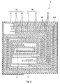
- Fig. 4 shows a construction of the secondary battery.
- This secondary battery is a so-called coin type battery.
- the electrode 10 as the anode housed in an exterior cup 20 and an electrode 40 as the cathode housed in an exterior can 30 are layered with a separator 50 in between.
- Peripheral parts of the exterior cup 20 and the exterior can 30 are hermetically closed through caulking by insulating gasket 60.
- the exterior cup 20 and the exterior can 30 are made of metals such as stainless and aluminum, respectively.
- the electrode 40 comprises, for example, a current collector 41, an active material layer 42 provided on the current collector 41.
- the electrode 40 is arranged so that the active material layer 42 side is facing the thin film layer 13.
- the current collector 41 is made of, for example, aluminum, nickel, stainless or the like.
- the active material layer 42 contains one or more cathode materials capable of inserting and extracting lithium as an active material.
- the active material layer 42 can contain a conductive material such as a carbon material, and a binder such as polyvinylidene fluoride as necessary.
- a cathode material capable of inserting and extracting lithium for example, lithium-containing metal complex oxides expressed by a general formula of Li x MIO 2 are preferable.
- the lithium-containing metal complex oxides can generate a high voltage and have a high density, so that further high capacity of the secondary battery can be obtained by using them.
- MI represents one or more transition metals, and is preferably at least one of cobalt and nickel, for example.
- x varies depending on charge and discharge state of the battery, and is generally a value in the range of 0.05 ⁇ x ⁇ 1.10. Concrete examples of such lithium-containing metal complex oxides include LiCoO 2 and LiNiO 2
- the electrode 40 can be formed by, for example, preparing a mixture by mixing an active material, a conductive material and a binder, dispersing this mixture in a carrier fluid such as N-methyl pyrrolidone to prepare a mixture slurry, applying this mixture slurry on the current collector 41 made of a metal foil and the like, and drying and compression-molding the resultant to form the active material layer 42.
- a carrier fluid such as N-methyl pyrrolidone
- the separator 50 is intended to separate the electrode 10 from the electrode 40, prevent a current short circuit due to contact between both the electrodes, and let through lithium ions.
- This separator 50 is made of, for example, polyethylene or polypropylene.
- An electrolytic solution of a liquid electrolyte is impregnated in the separator 50.
- This electrolytic solution contains, for example, a solvent and a lithium salt as an electrolyte salt dissolved in this solvent, and can contain an additive as necessary.
- the solvent include organic solvents such as ethylene carbonate, propylene carbonate, dimethyl carbonate, diethyl carbonate, and ethyl methyl carbonate. Either one of them or a mixture of two or more of them can be used.
- lithium salt examples include LiPF 6 , LiCF 3 , SO 3 , and LiClO 4 . Either one of them or a mixture of two or more of them can be used.
- This secondary battery can be manufactured, for example, by layering the electrode 10, the separator 50, wherein an electrolytic solution is impregnated, and the electrode 40, housing the layered body in the exterior cup 20 and the exterior can 30, and performing caulking.
- lithium ions are extracted from the electrode 40, and are inserted in the electrode 10 through the electrolytic solution.
- lithium ions are extracted from the electrode 10, and are inserted in the electrode 40 through the electrolytic solution.
- the active material layer 12 expands and shrinks.
- the current collector 11 contains a metal element which does not form an intermetallic compound with lithium, structural destruction of the current collector 11 itself is inhibited, and fall-off of the active material layer 12 from the current collector 11 is inhibited.
- the thin film layer 13 inhibits reaction between the active material layer 12 and the electrolytic solution, and inhibits structural destruction of the active material layer 12 according to its expansion and shrinkage. It is thought that lithium ions move between the electrolytic solution and the active material layer 12 via cracks or pin holes of the thin film layer 13, or by diffusing themselves in the thin film layer 13 in the case where the thin film layer 13 is thin.
- the electrode 10 according to the embodiment can also be used for an anode of the secondary battery as below.
- Fig. 5 shows a construction of the secondary battery.
- This secondary battery has a construction, wherein an electrode winding body 3 on which a lead 1 of a cathode and a lead 2 of an anode are attached is housed inside film exterior members 4A and 4B. A size, a weight, and a thickness of this secondary battery can be reduced.
- the leads 1 and 2 are directed from inside to outside of the exterior members 4A and 4B, and, for example, are derived in the same direction.
- the leads 1 and 2 are respectively made of a metal material such as aluminum, copper, nickel, and stainless, and are respectively in the shape of a thin plate or in the shape of a net.
- the exterior members 4A and 4B are made of an aluminum laminated film in the shape of a rectangle, wherein, for example, a nylon film, an aluminum foil, and a polyethylene film are bonded together in this order.
- the exterior members 4A and 4B are, for example, arranged so that their polyethylene film sides and the electrode winding body 3 are faced, and respective outer edge parts are fusion-bonded or adhered to each other.
- Adhesive films 5 to protect from outside air intrusion are inserted between the exterior member 4A and the lead 1, and the exterior member 4A and the lead 2, and the exterior member 4B and the lead 1, and the exterior member 4B and the lead 2.
- the adhesive film 5 is made of a material having contact characteristics in relation to the leads 1 and 2.
- the adhesive film 5 is made of a polyolefin resin such as polyethylene, polypropylene, modified polyethylene, and modified polypropylene.
- the exterior members 4A and 4B can be made of a laminated film having other structure, a high molecular weight film such as polypropylene, or a metal film, instead of the foregoing aluminum laminated film.
- Fig. 6 is a view showing a cross sectional structure taken along line VI-VI of the electrode winding body 3 illustrated in Fig. 5.
- the electrode winding body 3 is formed by layering and winding the electrode 10 as the anode and an electrode 70 as the cathode with a separator 80 and electrolyte layer 90 in between. An outermost peripheral part of the electrode winding body 3 is protected by a protective tape 100.
- the electrode 10 comprises, for example, the active material layer 12 provided on single side or on both sides of the current collector 11.
- the electrode 70 also comprises an active material layer 72 provided on single side or on both sides of a current collector 71. It is arranged so that the active material layer 72 side is facing the thin film layer 13. Constructions of the current collector 71, the active material layer 72 and the separator 80 are similar to those of the foregoing current collector 41, the active material layer 42 and the separator 50.
- the electrolyte layer 90 is made of a so-called gelatinous electrolyte, wherein an electrolytic solution is held by a holding body.
- the gelatinous electrolyte is preferable since high ion conductivity can be obtained, and battery leakage and swollenness due to high temperatures can be prevented.
- a construction of the electrolytic solution (that is, a solvent and an electrolyte salt) is similar to that of the coin type secondary battery shown in Fig. 4.
- the holding body is made of, for example, a high molecular weight material.
- the high molecular weight material include polyvinylidene fluoride, which is a block copolymer.
- This secondary battery can be manufactured as follows, for example.
- the electrolyte layer 90 wherein an electrolytic solution is held in a holding body is formed on the electrode 10 and the electrode 70, respectively.
- the lead 1 is attached to an end of the current collector 11 by welding or the like
- the lead 2 is attached to an end of the current collector 71 by welding or the like.
- the electrode 10 and the electrode 70, wherein the electrolyte layer 90 is respectively formed are layered with the separator 80 in between to obtain a layered body. Then, this layered body is wound in its longitudinal direction. The protective tape 100 is adhered to the outermost peripheral part to form the electrode winding body 3.
- the electrode winding body 3 is sandwiched between the exterior members 4A and 4B, and the electrode winding body 3 is enclosed by adhering outer edges of the exterior members 4A and 4B by thermal fusion bonding or the like.
- the adhesive films 5 are inserted between the lead 1 and the exterior member 4A, and the lead 1 and the exterior member 4B and the lead 2 and the exterior member 4A, and the lead 2 and the exterior member 4B.
- the secondary battery shown in Figs. 5 and 6 is thereby completed.
- This secondary battery acts similar to the coin type secondary battery shown in Fig. 4.
- the secondary battery comprises the current collector containing a metal element which does not form an intermetallic compound with lithium
- the secondary battery comprises the current collector containing at least one from the group consisting of copper, nickel, titanium, iron, and chromium. Therefore, there is no structural destruction of the current collector 11 according to formation of an intermetallic compound with lithium, and fall-off of the active material layer 12 from the current collector 11 associated expansion and shrinkage.
- the battery comprises the thin film layer 13 containing at least one of metal elements and metalloid elements which can form an solid solution with lithium and do not form an intermetallic compound, more specifically containing at least one of copper and nickel on the active material layer 12.
- reaction between the active material layer 12 and the electrolyte can be inhibited, and structural destruction of the active material layer 12 according to its expansion and shrinkage can be inhibited by covering the active material layer 12 with the thin film layer 13. In result, cycle characteristics can be improved.
- a thickness of the thin film layer 13 is 50 nm to 1,000 nm, reaction between the active material layer 12 and the electrolyte can be inhibited without deterioration of load characteristics.
- the active material layer 12 made of silicon having a thickness of 4 ⁇ m was formed on the current collector 11 made of a copper foil having a thickness of 20 ⁇ m by electron beam evaporation.
- the thin film layer 13 made of nickel or copper having a thickness of 200 ⁇ m was formed on the active material layer 12 by electron beam evaporation.
- the electrodes 10 of Examples 1-1 and 1-2 were thereby formed. Thicknesses of the active material layer 12 and the thin film layer 13 were verified by a SEM (Scanning Electron Microscope).
- charge and discharge tests were conducted at 25°C to obtain capacity retention ratio at 50th cycle.
- charge was performed firstly at a constant current density of 1 mA/cm 2 until a battery voltage reached 4.2 V, and then performed at a constant voltage of 4.2 V until a current density reached 0.02 mA/cm 2 .
- Discharge was performed at a constant current density of 1 mA/cm 2 until a battery voltage reached 2.5 V
- anode utility factor at an initial charge based on charge and discharge capacities of the electrode 10 and the electrode 40 previously obtained by actual measurement and calculation was set to 90% in order not to precipitate metal lithium.
- a capacity retention ratio at 50th cycle was calculated as a ratio of a discharge capacity at 50th cycle in relation to an initial discharge capacity, that is, (Discharge capacity at 50th cycle)/(initial discharge capacity) ⁇ 100. Obtained results are shown in Table 1.
- Comparative example 1-1 in relation to Examples 1-1 and 1-2 an electrode as an anode was fabricated in a manner similar to in Examples 1-1 and 1-2, except that a thin film layer was not formed.
- Comparative examples 1-2 and 1-3 in relation to Examples 1-1 and 1-2 electrodes as an anode were fabricated in a manner similar to in Examples 1-1 and 1-2, except that the thin film layer made of aluminum or titanium was formed.
- Comparative examples 1-4 and 1-5 in relation to Examples 1-1 and 1-2 electrodes as an anode were fabricated in a manner similar to in Examples 1-1 and 1-2, except that an aluminum foil was used as a current collector. In Comparative example 1-4, a thin film layer was not formed.
- Comparative example 1-5 a thin film layer made of aluminum was formed. Further, secondary batteries were fabricated by using the electrodes of Comparative examples 1-1 to 1-5 in a manner similar to in Examples 1-1 and 1-2. Regarding the secondary batteries of Comparative examples 1-1 to 1-5, charge and discharge tests were conducted as in Example 1-1, and capacity retention ratios at 50th cycle were obtained as well. These results are also shown in Table 1.
- the electrodes 10 were fabricated by forming the active material layer 12 by sintering method. Specifically, first, as the current collector 11, a copper foil or a titanium foil having a thickness of 20 ⁇ m was prepared. Next, a mixture slurry was prepared by adding N-methyl pyrrolidone into a mixture wherein silicon powders having an average particle diameter of 1 ⁇ m and polyvinylidene fluoride were mixed at a mass ratio of 9:1. This mixture slurry was applied to the current collector 11, heated, and N-methyl pyrrolidone was volatilized. Next, the resultant was pressurized, and heat-treated and sintered at 300°C for 8 hours in the argon atmosphere to form the active material layer 12.
- the thin film layer 13 made of copper having a thickness of 200 ⁇ m was formed by electron beam evaporation, or the thin film layer 13 made of nickel having a thickness of 200 ⁇ m was formed by electron beam evaporation.
- the electrode 10 was thereby fabricated. A thickness of the thin film layer 13 was verified by a SEM.
- Example 2-1 The obtained electrodes 10 of Examples 2-1 to 2-4 were analyzed by an AES (Auger Electron Spectroscopy) and an EDX (Energy Dispersive X-Ray Spectroscope). In result, it was confirmed that in Example 2-1, there was a mixture layer of components of the active material layer 12 and the current collector 11 in the vicinity of the interface between the active material layer 12 and the current collector 11, and there was a mixture layer of components of the active material layer 12 and the thin film layer 13 in the vicinity of the interface between the active material layer 12 and the thin film layer 13.
- AES Alger Electron Spectroscopy
- EDX Energy Dispersive X-Ray Spectroscope
- Example 2-2 alloying was confirmed only at part of the interface between the current collector 11 and the active material layer 12.
- Example 2-3 alloying was confirmed only at part of the interface between the active material layer 12 and the thin film layer 13.
- Example 2-4 alloying was not confirmed at any interface between the active material layer 12 and the current collector 11/the thin film layer 13.
- Example 2 in relation to Examples 2-1 to 2-4, an electrode as an anode was formed in a manner similar to in Examples 2-3 and 2-4, except that a thin film layer was not formed. Further, secondary batteries were fabricated by using the electrodes of Examples 2-1 to 2-4 and Comparative example 2 in a manner similar to in Example 1-1. Regarding the secondary batteries of Examples 2-1 to 2-4 and Comparative example 2, charge and discharge tests were also conducted and capacity retention ratios at 50th cycle were obtained as in Example 1-1. The results are shown in Table 2.
- the current collector 11 and the thin film layer 13 were made of copper, nickel, or titanium, which does not form an intermetallic compound with lithium, higher capacity retention ratios were obtained than in Comparative example 2, wherein a thin film layer was not formed. That is, it was found that when the active material layer 12 was formed by sintering method, cycle characteristics could be improved, if the current collector 11 containing the metal element which does not form an intermetallic compound with lithium was used, and the thin film layer containing a metal element which can make a solid solution with lithium and does not form an intermetallic compound with lithium was formed on the active material layer 12.
- Example 2-1 As evidenced by Examples 2-1 to 2-4, the capacity retention ratio of Example 2-1, wherein both the current collector 11 and the thin film layer 13 were respectively made of copper which is alloyed with silicon was the highest.
- the electrodes 10 were formed in a manner similar to in Example 1-1, except that the active material layer 12 made of germanium having a thickness of 4 ⁇ m was formed by electron beam evaporation, and thicknesses of the thin film layer 13 were changed as shown in Table 3. Thicknesses of the active material layer 12 and the thin film layer 13 were verified by a SEM.
- the electrode 70 was formed as in the electrode 40.
- the electrolyte layer 90 was formed by applying a precursor solution, wherein 10 wt% of polyvinylidene fluoride as a block copolymer having a weight-average molecular weight of 0.6 million and 60 wt% of dimethyl carbonate were mixed and dissolved in 30 wt% of electrolytic solution consisted of 42.5 wt% of ethylene carbonate, 42.5 wt% of propylene carbonate, and 15 wt% of LiPF 6 as a lithium salt to the electrode 10 and the electrode 70, respectively, keeping the resultant at ambient temperatures for 8 hours, and volatilizing dimethyl carbonate.
- Example 3 Current collector Active material layer Thin film layer Capacity retention ratio (%) Material Forming method Material Thickness (nm) Forming method
- Example 3-1 Cu Ge Electron beam evaporation Ni 10 Electron beam evaporation 72
- Example 3-2 Cu Ge Electron beam evaporation Ni 50
- Electron beam evaporation 81 Example 3-3 Cu Ge Electron beam evaporation Ni 300
- Electron beam evaporation 84 Example 3-4 Cu Ge Electron beam evaporation Ni 600 Electron beam evaporation 86
- Example 3-5 Cu Ge Electron beam evaporation Ni 1,000 Electron beam evaporation 78
- Example 3-6 Cu Ge Electron beam evaporation Ni 1,500 Electron beam evaporation 73 Comparative example 3 Cu Ge Electron beam evaporation - 0 - 69
- the electrode 10 was formed in a manner similar to in Example 3-3, except that the active material layer 12 was formed by coating.
- the active material layer 12 was formed by preparing a mixture slurry by adding N-methyl pyrrolidone into a mixture of germanium having an average particle diameter of 1 ⁇ m, graphitized vapor-phase growth carbon fiber, and polyvinylidene fluoride at a mass ratio of 85:5:10, applying this mixture slurry to the current collector 11, and then heating the resultant to volatilize N-methyl pyrrolidone, and pressurizing the resultant.
- an electrode as an anode was formed in a manner similar to in Example 4, except that a thin film layer was not formed.
- the secondary batteries were fabricated in a manner similar to in Example 3-3 by using the formed electrodes 10 of Example 4 and Comparative example 4. Further, regarding the obtained secondary batteries of Example 4 and Comparative example 4, charge and discharge tests were also conducted and capacity retention ratios at 50th cycle were obtained as in Example 1-1. The results are shown in Table 4 with the results of Example 3-3 and Comparative example 3.
- Example 4 As evidenced by Table 4, in Example 4, wherein the active material layer 12 was formed by coating, a higher capacity retention ratio than in corresponding Comparative example 4 was obtained as in Example 3-3, wherein the active material layer 12 was formed by vapor-phase deposition method. That is, it was found that when the active material layer 12 was formed by coating, cycle characteristics could be improved, if the current collector 11 containing a metal element which does not form an intermetallic compound with lithium was used, and the thin film layer containing a metal element which can make a solid solution with lithium and does not form an intermetallic compound with lithium is formed on the active material layer 12.
- the current collector 11 contained copper or titanium
- the thin film layer 13 contained nickel or copper.
- similar results can be obtained when other element which does not form an intermetallic compound with lithium is contained.
- similar results can be also obtained, when the active material layer 12 is formed by vapor-phase deposition method, other sintering method, or liquid-phase deposition method, instead of electron beam evaporation.
- similar results can be also obtained when the thin film layer 13 is formed by vapor-phase deposition method, sintering method, or liquid-phase deposition method, instead of electron beam evaporation.
- the electrode 10, wherein the active material layer 12 is provided on the current collector 11 has been described.
- other layer can be provided between a current collector and an active material layer.
- other layer can be provided between an active material layer and a thin film layer.
- the secondary batteries in the shape of a coin or a winding laminated body have been described.
- the invention can be applied to secondary batteries such as a cylinder type, a square type, a button type, a thin type, a large type, and a layered laminated type secondary batteries. Further, this invention can be applied not only to secondary batteries, but also to primary batteries.
- a current collector containing at least one from the group consisting of copper, nickel, titanium, iron, and chromium; or a current collector containing a metal element which does not form an intermetallic compound with lithium is provided. Therefore, there is no structural destruction of the current collector according to formation of an intermetallic compound with lithium, and fall-off of the active material layer from the current collector due to expansion and shrinkage can be inhibited.
- a thin film layer containing at least one of copper and nickel, or a thin film layer containing at least one of metal elements and metalloid elements which can make a solid solution with lithium and do not form an intermetallic compound with lithium is provided on the active material layer. Therefore, reaction between the active material layer and the electrolyte can be inhibited, and structural destruction of the active material layer according to its expansion and shrinkage can be inhibited by covering the active material layer with the thin film layer. In result, cycle characteristics can be improved.
- the current collector is alloyed with the active material layer at least on part of the interface thereof. Therefore, structural destruction of the active material layer can be further inhibited.
- the active material layer is alloyed with the thin film layer at least on part of the interface thereof. Therefore, reaction between the active material layer and the electrolyte can be further inhibited.
- a thickness of the thin film layer is 50 nm to 1,000 nm. Therefore, reaction between the active material layer and the electrolyte can be inhibited without deterioration of load characteristics.
- the holding body, the solvent, and the electrolyte salt were contained. Therefore, high ion conductivity can be obtained, and battery leakage or swollenness due to high temperatures can be prevented.
Landscapes
- Chemical & Material Sciences (AREA)
- Electrochemistry (AREA)
- General Chemical & Material Sciences (AREA)
- Chemical Kinetics & Catalysis (AREA)
- Engineering & Computer Science (AREA)
- Materials Engineering (AREA)
- Composite Materials (AREA)
- Manufacturing & Machinery (AREA)
- Life Sciences & Earth Sciences (AREA)
- Environmental Sciences (AREA)
- Battery Electrode And Active Subsutance (AREA)
- Secondary Cells (AREA)
- Cell Electrode Carriers And Collectors (AREA)
Applications Claiming Priority (2)
| Application Number | Priority Date | Filing Date | Title |
|---|---|---|---|
| JP2003101189 | 2003-04-04 | ||
| JP2003101189A JP2004311141A (ja) | 2003-04-04 | 2003-04-04 | 電極およびそれを用いた電池 |
Publications (2)
| Publication Number | Publication Date |
|---|---|
| EP1465268A2 true EP1465268A2 (fr) | 2004-10-06 |
| EP1465268A3 EP1465268A3 (fr) | 2005-12-21 |
Family
ID=32844715
Family Applications (1)
| Application Number | Title | Priority Date | Filing Date |
|---|---|---|---|
| EP04007960A Withdrawn EP1465268A3 (fr) | 2003-04-04 | 2004-04-01 | Electrode et son utilisation dans une batterie |
Country Status (5)
| Country | Link |
|---|---|
| US (1) | US7838147B2 (fr) |
| EP (1) | EP1465268A3 (fr) |
| JP (1) | JP2004311141A (fr) |
| KR (1) | KR101164232B1 (fr) |
| CN (1) | CN1332458C (fr) |
Cited By (13)
| Publication number | Priority date | Publication date | Assignee | Title |
|---|---|---|---|---|
| WO2008116694A1 (fr) * | 2007-03-26 | 2008-10-02 | Nv Bekaert Sa | Substrat pour une batterie à couches minces au lithium |
| US8940610B2 (en) | 2010-04-16 | 2015-01-27 | Semiconductor Energy Laboratory Co., Ltd. | Electrode for energy storage device and method for manufacturing the same |
| US9735419B2 (en) | 2010-03-26 | 2017-08-15 | Semiconductor Energy Laboratory Co., Ltd. | Secondary battery and method for forming electrode of secondary battery |
| EP3542410A4 (fr) * | 2016-11-16 | 2020-09-30 | Enovix Corporation | Batteries tridimensionnelles à cathodes compressibles |
| US11081718B2 (en) | 2016-05-13 | 2021-08-03 | Enovix Corporation | Dimensional constraints for three-dimensional batteries |
| US11128020B2 (en) | 2017-11-15 | 2021-09-21 | Enovix Corporation | Electrode assembly, secondary battery, and method of manufacture |
| US11205803B2 (en) | 2017-11-15 | 2021-12-21 | Enovix Corporation | Constrained electrode assembly |
| US11211639B2 (en) | 2018-08-06 | 2021-12-28 | Enovix Corporation | Electrode assembly manufacture and device |
| US11239488B2 (en) | 2015-05-14 | 2022-02-01 | Enovix Corporation | Longitudinal constraints for energy storage devices |
| US11355816B2 (en) | 2013-03-15 | 2022-06-07 | Enovix Operations Inc. | Separators for three-dimensional batteries |
| US11411253B2 (en) | 2020-12-09 | 2022-08-09 | Enovix Operations Inc. | Apparatus, systems and methods for the production of electrodes, electrode stacks and batteries |
| US11495784B2 (en) | 2020-09-18 | 2022-11-08 | Enovix Operations Inc. | Apparatus, systems and methods for the production of electrodes for use in batteries |
| US11600848B2 (en) | 2012-08-16 | 2023-03-07 | Enovix Corporation | Electrode structures for three-dimensional batteries |
Families Citing this family (32)
| Publication number | Priority date | Publication date | Assignee | Title |
|---|---|---|---|---|
| JP2006156235A (ja) * | 2004-11-30 | 2006-06-15 | Sony Corp | 負極および電池 |
| JP4739781B2 (ja) * | 2005-03-11 | 2011-08-03 | 三洋電機株式会社 | リチウム二次電池 |
| JP4891555B2 (ja) * | 2005-03-14 | 2012-03-07 | 三井金属鉱業株式会社 | 非水電解液二次電池の製造方法 |
| KR100790844B1 (ko) * | 2005-06-01 | 2008-01-02 | 강원대학교산학협력단 | 박막 전지 및 그 제조 방법 |
| JP2007026926A (ja) * | 2005-07-19 | 2007-02-01 | Nec Corp | 二次電池用負極およびこれを用いた二次電池 |
| EP1950789A4 (fr) * | 2005-11-04 | 2011-05-11 | Nagayama Ip Holdings Llc | Plaque de phase pour microscope electronique et son procede de fabrication |
| WO2008089110A1 (fr) | 2007-01-12 | 2008-07-24 | Microazure Corporation | Batteries tridimensionnelles et procédés de fabrication correspondants |
| US9166230B1 (en) | 2007-01-12 | 2015-10-20 | Enovix Corporation | Three-dimensional battery having current-reducing devices corresponding to electrodes |
| JP5470696B2 (ja) | 2007-10-31 | 2014-04-16 | ソニー株式会社 | リチウムイオン二次電池用負極およびリチウムイオン二次電池 |
| US8475957B2 (en) | 2008-04-17 | 2013-07-02 | Enovix Corporation | Negative electrode structure for non-aqueous lithium secondary battery |
| US8367244B2 (en) * | 2008-04-17 | 2013-02-05 | Enovix Corporation | Anode material having a uniform metal-semiconductor alloy layer |
| US8133613B2 (en) | 2008-04-17 | 2012-03-13 | Enovix Corporation | Nonaqueous electrolyte secondary battery anode material with a uniform metal-semiconductor alloy layer |
| JP4947386B2 (ja) * | 2008-11-14 | 2012-06-06 | ソニー株式会社 | リチウムイオン二次電池およびリチウムイオン二次電池用負極 |
| CN102823028B (zh) * | 2010-03-26 | 2016-06-29 | 株式会社半导体能源研究所 | 二次电池及二次电池的电极的制造方法 |
| JP5859746B2 (ja) * | 2010-05-28 | 2016-02-16 | 株式会社半導体エネルギー研究所 | 蓄電装置およびその作製方法 |
| KR101874935B1 (ko) * | 2010-06-30 | 2018-07-05 | 가부시키가이샤 한도오따이 에네루기 켄큐쇼 | 축전 장치 및 그 제조 방법 |
| US9843027B1 (en) | 2010-09-14 | 2017-12-12 | Enovix Corporation | Battery cell having package anode plate in contact with a plurality of dies |
| WO2012111657A1 (fr) * | 2011-02-18 | 2012-08-23 | 住友電気工業株式会社 | Maille poreuse tridimensionnelle en aluminium destinée à être utilisée dans un collecteur, et collecteur, électrode, batterie à électrolyte non aqueux, condensateur et condensateur au lithium-ion utilisant ladite maille poreuse en aluminium |
| JP5708333B2 (ja) * | 2011-07-19 | 2015-04-30 | 日本電気株式会社 | 二次電池用負極およびこれを用いた二次電池 |
| CN103022415A (zh) * | 2011-09-26 | 2013-04-03 | 比亚迪股份有限公司 | 一种正极及其制备方法以及一种锂离子电池 |
| EP2807698B1 (fr) | 2012-01-24 | 2018-01-10 | Enovix Corporation | Structures perméables aux ions destinées à des dispositifs de stockage d'énergie |
| US8841030B2 (en) | 2012-01-24 | 2014-09-23 | Enovix Corporation | Microstructured electrode structures |
| EP2888778A1 (fr) | 2012-08-21 | 2015-07-01 | Kratos LLC | Particules fonctionnalisées du groupe iva et leurs procédés d'utilisation |
| US9461309B2 (en) | 2012-08-21 | 2016-10-04 | Kratos LLC | Group IVA functionalized particles and methods of use thereof |
| JP6076802B2 (ja) * | 2013-03-29 | 2017-02-08 | 藤倉ゴム工業株式会社 | リチウムイオン二次電池用負極の製造方法 |
| KR101595613B1 (ko) * | 2013-05-06 | 2016-02-18 | 주식회사 엘지화학 | 리튬 이차전지용 음극 및 이를 포함하는 리튬이온 이차 전지 |
| US10170747B2 (en) * | 2013-06-14 | 2019-01-01 | Ford Global Technologies, Llc | Treated current collector foil |
| BR112019000112A2 (pt) | 2016-07-05 | 2019-04-09 | Kratos LLC | partículas do grupo iva micrônicas e sub-micrônicas pré-litiadas passivadas e métodos de preparação das mesmas |
| WO2018183909A1 (fr) | 2017-03-31 | 2018-10-04 | Kratos LLC | Matériau d'électrode négative préchargé pour batterie secondaire |
| KR102355101B1 (ko) | 2018-10-18 | 2022-02-04 | 주식회사 엘지에너지솔루션 | 삼차원 구조 전극 및 이를 포함하는 전기화학소자 |
| CN111628138B (zh) * | 2020-06-29 | 2023-08-18 | 天津市捷威动力工业有限公司 | 一种电极的制备方法及用途 |
| CN114361428B (zh) * | 2021-12-31 | 2024-05-17 | 远景动力技术(江苏)有限公司 | 三维锂负极及其应用 |
Citations (1)
| Publication number | Priority date | Publication date | Assignee | Title |
|---|---|---|---|---|
| US6235427B1 (en) * | 1998-05-13 | 2001-05-22 | Fuji Photo Film Co., Ltd. | Nonaqueous secondary battery containing silicic material |
Family Cites Families (11)
| Publication number | Priority date | Publication date | Assignee | Title |
|---|---|---|---|---|
| JP3495814B2 (ja) | 1994-05-30 | 2004-02-09 | キヤノン株式会社 | 電池用電極及び該電極を有するリチウム二次電池 |
| EP1052711A4 (fr) | 1998-12-02 | 2005-03-30 | Matsushita Electric Industrial Co Ltd | Cellule secondaire d'electrolyte du type non aqueux |
| WO2001029918A1 (fr) | 1999-10-22 | 2001-04-26 | Sanyo Electric Co., Ltd | Electrode pour accumulateur au lithium et accumulateur au lithium |
| US20010033973A1 (en) * | 2000-01-13 | 2001-10-25 | Krause Larry J. | Electrode compositions having improved cycling behavior |
| US6664004B2 (en) | 2000-01-13 | 2003-12-16 | 3M Innovative Properties Company | Electrode compositions having improved cycling behavior |
| JP4212263B2 (ja) | 2000-09-01 | 2009-01-21 | 三洋電機株式会社 | リチウム二次電池用負極及びその製造方法 |
| JP2002231224A (ja) | 2001-01-30 | 2002-08-16 | Sanyo Electric Co Ltd | リチウム二次電池用電極及びその製造方法並びにリチウム二次電池 |
| JP4152086B2 (ja) | 2001-03-23 | 2008-09-17 | 三洋電機株式会社 | リチウム二次電池用電極及びリチウム二次電池 |
| US6984470B2 (en) * | 2001-03-26 | 2006-01-10 | Kabushiki Kaisha Toshiba | Positive electrode active material and nonaqueous electrolyte secondary battery |
| JP2002313319A (ja) * | 2001-04-09 | 2002-10-25 | Sanyo Electric Co Ltd | リチウム二次電池用電極及びリチウム二次電池 |
| US6991662B2 (en) | 2001-09-10 | 2006-01-31 | Polyplus Battery Company | Encapsulated alloy electrodes |
-
2003
- 2003-04-04 JP JP2003101189A patent/JP2004311141A/ja active Pending
-
2004
- 2004-03-30 US US10/813,370 patent/US7838147B2/en active Active
- 2004-04-01 EP EP04007960A patent/EP1465268A3/fr not_active Withdrawn
- 2004-04-02 KR KR1020040022910A patent/KR101164232B1/ko not_active Expired - Lifetime
- 2004-04-04 CN CNB2004100477657A patent/CN1332458C/zh not_active Expired - Lifetime
Patent Citations (1)
| Publication number | Priority date | Publication date | Assignee | Title |
|---|---|---|---|---|
| US6235427B1 (en) * | 1998-05-13 | 2001-05-22 | Fuji Photo Film Co., Ltd. | Nonaqueous secondary battery containing silicic material |
Cited By (32)
| Publication number | Priority date | Publication date | Assignee | Title |
|---|---|---|---|---|
| WO2008116694A1 (fr) * | 2007-03-26 | 2008-10-02 | Nv Bekaert Sa | Substrat pour une batterie à couches minces au lithium |
| US9735419B2 (en) | 2010-03-26 | 2017-08-15 | Semiconductor Energy Laboratory Co., Ltd. | Secondary battery and method for forming electrode of secondary battery |
| US8940610B2 (en) | 2010-04-16 | 2015-01-27 | Semiconductor Energy Laboratory Co., Ltd. | Electrode for energy storage device and method for manufacturing the same |
| US11600848B2 (en) | 2012-08-16 | 2023-03-07 | Enovix Corporation | Electrode structures for three-dimensional batteries |
| US12009473B2 (en) | 2012-08-16 | 2024-06-11 | Enovix Corporation | Electrode structures for three-dimensional batteries |
| US12244036B2 (en) | 2013-03-15 | 2025-03-04 | Enovix Corporation | Separators for three-dimensional batteries |
| US11355816B2 (en) | 2013-03-15 | 2022-06-07 | Enovix Operations Inc. | Separators for three-dimensional batteries |
| US12327833B2 (en) | 2015-05-14 | 2025-06-10 | Enovix Corporation | Longitudinal constraints for energy storage devices |
| US11894512B2 (en) | 2015-05-14 | 2024-02-06 | Enovix Corporation | Longitudinal constraints for energy storage devices |
| US11239488B2 (en) | 2015-05-14 | 2022-02-01 | Enovix Corporation | Longitudinal constraints for energy storage devices |
| US12347821B2 (en) | 2016-05-13 | 2025-07-01 | Enovix Corporation | Dimensional constraints for three-dimensional batteries |
| US11081718B2 (en) | 2016-05-13 | 2021-08-03 | Enovix Corporation | Dimensional constraints for three-dimensional batteries |
| US11444310B2 (en) | 2016-05-13 | 2022-09-13 | Enovix Operations Inc. | Dimensional constraints for three-dimensional batteries |
| US11961952B2 (en) | 2016-05-13 | 2024-04-16 | Enovix Corporation | Dimensional constraints for three-dimensional batteries |
| US12418050B2 (en) | 2016-11-16 | 2025-09-16 | Enovix Corporation | Three-dimensional batteries with compressible cathodes |
| US11063299B2 (en) | 2016-11-16 | 2021-07-13 | Enovix Corporation | Three-dimensional batteries with compressible cathodes |
| EP3542410A4 (fr) * | 2016-11-16 | 2020-09-30 | Enovix Corporation | Batteries tridimensionnelles à cathodes compressibles |
| US11901514B2 (en) | 2016-11-16 | 2024-02-13 | Enovix Corporation | Three-dimensional batteries with compressible cathodes |
| US12095040B2 (en) | 2017-11-15 | 2024-09-17 | Enovix Corporation | Constrained electrode assembly |
| US12206106B2 (en) | 2017-11-15 | 2025-01-21 | Enovix Corporation | Electrode assembly and secondary battery |
| US11600864B2 (en) | 2017-11-15 | 2023-03-07 | Enovix Corporation | Constrained electrode assembly |
| US11128020B2 (en) | 2017-11-15 | 2021-09-21 | Enovix Corporation | Electrode assembly, secondary battery, and method of manufacture |
| US12087947B2 (en) | 2017-11-15 | 2024-09-10 | Enovix Corporation | Electrode assembly, secondary battery, and method of manufacture |
| US11205803B2 (en) | 2017-11-15 | 2021-12-21 | Enovix Corporation | Constrained electrode assembly |
| US11264680B2 (en) | 2017-11-15 | 2022-03-01 | Enovix Corporation | Electrode assembly and secondary battery |
| US12183892B2 (en) | 2018-08-06 | 2024-12-31 | Enovix Corporation | Electrode assembly manufacture and device |
| US11211639B2 (en) | 2018-08-06 | 2021-12-28 | Enovix Corporation | Electrode assembly manufacture and device |
| US11811047B2 (en) | 2020-09-18 | 2023-11-07 | Enovix Corporation | Apparatus, systems and methods for the production of electrodes for use in batteries |
| US12095072B2 (en) | 2020-09-18 | 2024-09-17 | Enovix Corporation | Apparatus, systems and methods for the production of electrodes for use in batteries |
| US11495784B2 (en) | 2020-09-18 | 2022-11-08 | Enovix Operations Inc. | Apparatus, systems and methods for the production of electrodes for use in batteries |
| US11411253B2 (en) | 2020-12-09 | 2022-08-09 | Enovix Operations Inc. | Apparatus, systems and methods for the production of electrodes, electrode stacks and batteries |
| US12500274B2 (en) | 2020-12-09 | 2025-12-16 | Enovix Corporation | Apparatus including rotating assemblies to move webs along merge paths and receiving member to overlay webs, and methods for the production of electrodes assemblies |
Also Published As
| Publication number | Publication date |
|---|---|
| US20040234861A1 (en) | 2004-11-25 |
| CN1332458C (zh) | 2007-08-15 |
| EP1465268A3 (fr) | 2005-12-21 |
| US7838147B2 (en) | 2010-11-23 |
| KR20040086818A (ko) | 2004-10-12 |
| CN1677723A (zh) | 2005-10-05 |
| JP2004311141A (ja) | 2004-11-04 |
| KR101164232B1 (ko) | 2012-07-09 |
Similar Documents
| Publication | Publication Date | Title |
|---|---|---|
| US7838147B2 (en) | Electrode and battery using it | |
| US7311999B2 (en) | Anode for a battery and a battery using an anode | |
| US7459236B2 (en) | Battery | |
| US7459233B2 (en) | Anode and battery | |
| US7416817B2 (en) | Battery | |
| US9246160B2 (en) | Anode and battery using the same | |
| US20160133941A1 (en) | Anode and battery | |
| US7655354B2 (en) | Battery | |
| JP4318025B2 (ja) | 負極およびそれを用いた電池、並びにそれらの製造方法 | |
| US20060216604A1 (en) | Anode, battery, and method of manufacturing same | |
| US20040166409A1 (en) | Anode and battery using the same | |
| JP2004171875A (ja) | 負極およびそれを用いた電池 | |
| US7482095B2 (en) | Anode and battery using the same | |
| JP3786277B2 (ja) | 負極および電池 | |
| US7524585B2 (en) | Anode and battery using it | |
| JP2007019032A (ja) | 電池 | |
| JP2005050806A (ja) | 負極およびそれを用いた電池 |
Legal Events
| Date | Code | Title | Description |
|---|---|---|---|
| PUAI | Public reference made under article 153(3) epc to a published international application that has entered the european phase |
Free format text: ORIGINAL CODE: 0009012 |
|
| AK | Designated contracting states |
Kind code of ref document: A2 Designated state(s): AT BE BG CH CY CZ DE DK EE ES FI FR GB GR HU IE IT LI LU MC NL PL PT RO SE SI SK TR |
|
| AX | Request for extension of the european patent |
Extension state: AL HR LT LV MK |
|
| PUAL | Search report despatched |
Free format text: ORIGINAL CODE: 0009013 |
|
| AK | Designated contracting states |
Kind code of ref document: A3 Designated state(s): AT BE BG CH CY CZ DE DK EE ES FI FR GB GR HU IE IT LI LU MC NL PL PT RO SE SI SK TR |
|
| AX | Request for extension of the european patent |
Extension state: AL HR LT LV MK |
|
| 17P | Request for examination filed |
Effective date: 20060522 |
|
| AKX | Designation fees paid |
Designated state(s): DE FR GB |
|
| 17Q | First examination report despatched |
Effective date: 20060920 |
|
| STAA | Information on the status of an ep patent application or granted ep patent |
Free format text: STATUS: THE APPLICATION IS DEEMED TO BE WITHDRAWN |
|
| 18D | Application deemed to be withdrawn |
Effective date: 20150505 |