EP1467149B1 - Méthode pour surveiller la combustion dans un dispositif de combustion - Google Patents
Méthode pour surveiller la combustion dans un dispositif de combustion Download PDFInfo
- Publication number
- EP1467149B1 EP1467149B1 EP04007876A EP04007876A EP1467149B1 EP 1467149 B1 EP1467149 B1 EP 1467149B1 EP 04007876 A EP04007876 A EP 04007876A EP 04007876 A EP04007876 A EP 04007876A EP 1467149 B1 EP1467149 B1 EP 1467149B1
- Authority
- EP
- European Patent Office
- Prior art keywords
- gas
- setpoint
- measurements
- probe
- exhaust gas
- Prior art date
- Legal status (The legal status is an assumption and is not a legal conclusion. Google has not performed a legal analysis and makes no representation as to the accuracy of the status listed.)
- Expired - Lifetime
Links
- 238000002485 combustion reaction Methods 0.000 title claims abstract description 44
- 238000000034 method Methods 0.000 title claims abstract description 23
- 239000007789 gas Substances 0.000 claims abstract description 101
- 239000000523 sample Substances 0.000 claims abstract description 36
- VNWKTOKETHGBQD-UHFFFAOYSA-N methane Chemical compound C VNWKTOKETHGBQD-UHFFFAOYSA-N 0.000 claims abstract description 26
- 238000012937 correction Methods 0.000 claims abstract description 23
- 238000011156 evaluation Methods 0.000 claims abstract description 22
- 230000008859 change Effects 0.000 claims abstract description 18
- 230000009467 reduction Effects 0.000 claims abstract description 18
- 239000003345 natural gas Substances 0.000 claims abstract description 13
- 238000012544 monitoring process Methods 0.000 claims abstract description 9
- 238000005259 measurement Methods 0.000 claims description 23
- 239000003344 environmental pollutant Substances 0.000 claims description 18
- 231100000719 pollutant Toxicity 0.000 claims description 18
- 238000011144 upstream manufacturing Methods 0.000 claims description 6
- 238000010586 diagram Methods 0.000 claims description 5
- 238000009529 body temperature measurement Methods 0.000 claims 2
- QVGXLLKOCUKJST-UHFFFAOYSA-N atomic oxygen Chemical compound [O] QVGXLLKOCUKJST-UHFFFAOYSA-N 0.000 abstract description 4
- 239000001301 oxygen Substances 0.000 abstract description 4
- 229910052760 oxygen Inorganic materials 0.000 abstract description 4
- CURLTUGMZLYLDI-UHFFFAOYSA-N Carbon dioxide Chemical compound O=C=O CURLTUGMZLYLDI-UHFFFAOYSA-N 0.000 abstract 2
- 229910002092 carbon dioxide Inorganic materials 0.000 abstract 1
- 239000001569 carbon dioxide Substances 0.000 abstract 1
- UGFAIRIUMAVXCW-UHFFFAOYSA-N Carbon monoxide Chemical compound [O+]#[C-] UGFAIRIUMAVXCW-UHFFFAOYSA-N 0.000 description 13
- 229910002091 carbon monoxide Inorganic materials 0.000 description 13
- 239000003054 catalyst Substances 0.000 description 11
- MWUXSHHQAYIFBG-UHFFFAOYSA-N nitrogen oxide Inorganic materials O=[N] MWUXSHHQAYIFBG-UHFFFAOYSA-N 0.000 description 10
- 238000001514 detection method Methods 0.000 description 7
- 230000032683 aging Effects 0.000 description 5
- 239000000203 mixture Substances 0.000 description 5
- 230000006378 damage Effects 0.000 description 4
- 230000033228 biological regulation Effects 0.000 description 3
- 230000000694 effects Effects 0.000 description 3
- 239000000446 fuel Substances 0.000 description 3
- 239000002737 fuel gas Substances 0.000 description 3
- 238000004519 manufacturing process Methods 0.000 description 3
- 231100000572 poisoning Toxicity 0.000 description 3
- 230000000607 poisoning effect Effects 0.000 description 3
- 230000004044 response Effects 0.000 description 3
- 230000006978 adaptation Effects 0.000 description 2
- 230000007547 defect Effects 0.000 description 2
- 230000007613 environmental effect Effects 0.000 description 2
- 239000003502 gasoline Substances 0.000 description 2
- 230000020169 heat generation Effects 0.000 description 2
- 229930195733 hydrocarbon Natural products 0.000 description 2
- 150000002430 hydrocarbons Chemical class 0.000 description 2
- 239000011261 inert gas Substances 0.000 description 2
- 230000007774 longterm Effects 0.000 description 2
- 239000000126 substance Substances 0.000 description 2
- 230000009692 acute damage Effects 0.000 description 1
- 230000000712 assembly Effects 0.000 description 1
- 238000000429 assembly Methods 0.000 description 1
- 230000003197 catalytic effect Effects 0.000 description 1
- 238000006243 chemical reaction Methods 0.000 description 1
- 239000000567 combustion gas Substances 0.000 description 1
- 238000009833 condensation Methods 0.000 description 1
- 230000005494 condensation Effects 0.000 description 1
- 230000002596 correlated effect Effects 0.000 description 1
- 230000000875 corresponding effect Effects 0.000 description 1
- 230000007423 decrease Effects 0.000 description 1
- 230000001419 dependent effect Effects 0.000 description 1
- 239000011521 glass Substances 0.000 description 1
- 238000010438 heat treatment Methods 0.000 description 1
- 230000001771 impaired effect Effects 0.000 description 1
- 238000002347 injection Methods 0.000 description 1
- 239000007924 injection Substances 0.000 description 1
- 239000007788 liquid Substances 0.000 description 1
- 229910052751 metal Inorganic materials 0.000 description 1
- 239000002184 metal Substances 0.000 description 1
- 238000012806 monitoring device Methods 0.000 description 1
- IEQIEDJGQAUEQZ-UHFFFAOYSA-N phthalocyanine Chemical compound N1C(N=C2C3=CC=CC=C3C(N=C3C4=CC=CC=C4C(=N4)N3)=N2)=C(C=CC=C2)C2=C1N=C1C2=CC=CC=C2C4=N1 IEQIEDJGQAUEQZ-UHFFFAOYSA-N 0.000 description 1
- 230000001105 regulatory effect Effects 0.000 description 1
- 230000001052 transient effect Effects 0.000 description 1
Images


Classifications
-
- F—MECHANICAL ENGINEERING; LIGHTING; HEATING; WEAPONS; BLASTING
- F23—COMBUSTION APPARATUS; COMBUSTION PROCESSES
- F23N—REGULATING OR CONTROLLING COMBUSTION
- F23N5/00—Systems for controlling combustion
- F23N5/02—Systems for controlling combustion using devices responsive to thermal changes or to thermal expansion of a medium
- F23N5/022—Systems for controlling combustion using devices responsive to thermal changes or to thermal expansion of a medium using electronic means
-
- F—MECHANICAL ENGINEERING; LIGHTING; HEATING; WEAPONS; BLASTING
- F02—COMBUSTION ENGINES; HOT-GAS OR COMBUSTION-PRODUCT ENGINE PLANTS
- F02D—CONTROLLING COMBUSTION ENGINES
- F02D17/00—Controlling engines by cutting out individual cylinders; Rendering engines inoperative or idling
- F02D17/04—Controlling engines by cutting out individual cylinders; Rendering engines inoperative or idling rendering engines inoperative or idling, e.g. caused by abnormal conditions
-
- F—MECHANICAL ENGINEERING; LIGHTING; HEATING; WEAPONS; BLASTING
- F02—COMBUSTION ENGINES; HOT-GAS OR COMBUSTION-PRODUCT ENGINE PLANTS
- F02D—CONTROLLING COMBUSTION ENGINES
- F02D41/00—Electrical control of supply of combustible mixture or its constituents
- F02D41/0025—Controlling engines characterised by use of non-liquid fuels, pluralities of fuels, or non-fuel substances added to the combustible mixtures
- F02D41/0027—Controlling engines characterised by use of non-liquid fuels, pluralities of fuels, or non-fuel substances added to the combustible mixtures the fuel being gaseous
-
- F—MECHANICAL ENGINEERING; LIGHTING; HEATING; WEAPONS; BLASTING
- F02—COMBUSTION ENGINES; HOT-GAS OR COMBUSTION-PRODUCT ENGINE PLANTS
- F02D—CONTROLLING COMBUSTION ENGINES
- F02D41/00—Electrical control of supply of combustible mixture or its constituents
- F02D41/22—Safety or indicating devices for abnormal conditions
-
- F—MECHANICAL ENGINEERING; LIGHTING; HEATING; WEAPONS; BLASTING
- F23—COMBUSTION APPARATUS; COMBUSTION PROCESSES
- F23N—REGULATING OR CONTROLLING COMBUSTION
- F23N1/00—Regulating fuel supply
- F23N1/02—Regulating fuel supply conjointly with air supply
- F23N1/022—Regulating fuel supply conjointly with air supply using electronic means
-
- F—MECHANICAL ENGINEERING; LIGHTING; HEATING; WEAPONS; BLASTING
- F23—COMBUSTION APPARATUS; COMBUSTION PROCESSES
- F23N—REGULATING OR CONTROLLING COMBUSTION
- F23N5/00—Systems for controlling combustion
- F23N5/003—Systems for controlling combustion using detectors sensitive to combustion gas properties
-
- F—MECHANICAL ENGINEERING; LIGHTING; HEATING; WEAPONS; BLASTING
- F02—COMBUSTION ENGINES; HOT-GAS OR COMBUSTION-PRODUCT ENGINE PLANTS
- F02D—CONTROLLING COMBUSTION ENGINES
- F02D41/00—Electrical control of supply of combustible mixture or its constituents
- F02D41/02—Circuit arrangements for generating control signals
- F02D41/14—Introducing closed-loop corrections
- F02D41/1438—Introducing closed-loop corrections using means for determining characteristics of the combustion gases; Sensors therefor
- F02D41/1444—Introducing closed-loop corrections using means for determining characteristics of the combustion gases; Sensors therefor characterised by the characteristics of the combustion gases
- F02D41/146—Introducing closed-loop corrections using means for determining characteristics of the combustion gases; Sensors therefor characterised by the characteristics of the combustion gases the characteristics being an NOx content or concentration
- F02D41/1463—Introducing closed-loop corrections using means for determining characteristics of the combustion gases; Sensors therefor characterised by the characteristics of the combustion gases the characteristics being an NOx content or concentration of the exhaust gases downstream of exhaust gas treatment apparatus
-
- F—MECHANICAL ENGINEERING; LIGHTING; HEATING; WEAPONS; BLASTING
- F23—COMBUSTION APPARATUS; COMBUSTION PROCESSES
- F23N—REGULATING OR CONTROLLING COMBUSTION
- F23N2223/00—Signal processing; Details thereof
- F23N2223/10—Correlation
-
- F—MECHANICAL ENGINEERING; LIGHTING; HEATING; WEAPONS; BLASTING
- F23—COMBUSTION APPARATUS; COMBUSTION PROCESSES
- F23N—REGULATING OR CONTROLLING COMBUSTION
- F23N2223/00—Signal processing; Details thereof
- F23N2223/14—Differentiation
-
- F—MECHANICAL ENGINEERING; LIGHTING; HEATING; WEAPONS; BLASTING
- F23—COMBUSTION APPARATUS; COMBUSTION PROCESSES
- F23N—REGULATING OR CONTROLLING COMBUSTION
- F23N2225/00—Measuring
- F23N2225/08—Measuring temperature
- F23N2225/10—Measuring temperature stack temperature
-
- F—MECHANICAL ENGINEERING; LIGHTING; HEATING; WEAPONS; BLASTING
- F23—COMBUSTION APPARATUS; COMBUSTION PROCESSES
- F23N—REGULATING OR CONTROLLING COMBUSTION
- F23N2237/00—Controlling
- F23N2237/08—Controlling two or more different types of fuel simultaneously
-
- F—MECHANICAL ENGINEERING; LIGHTING; HEATING; WEAPONS; BLASTING
- F23—COMBUSTION APPARATUS; COMBUSTION PROCESSES
- F23N—REGULATING OR CONTROLLING COMBUSTION
- F23N5/00—Systems for controlling combustion
- F23N5/003—Systems for controlling combustion using detectors sensitive to combustion gas properties
- F23N5/006—Systems for controlling combustion using detectors sensitive to combustion gas properties the detector being sensitive to oxygen
-
- Y—GENERAL TAGGING OF NEW TECHNOLOGICAL DEVELOPMENTS; GENERAL TAGGING OF CROSS-SECTIONAL TECHNOLOGIES SPANNING OVER SEVERAL SECTIONS OF THE IPC; TECHNICAL SUBJECTS COVERED BY FORMER USPC CROSS-REFERENCE ART COLLECTIONS [XRACs] AND DIGESTS
- Y02—TECHNOLOGIES OR APPLICATIONS FOR MITIGATION OR ADAPTATION AGAINST CLIMATE CHANGE
- Y02T—CLIMATE CHANGE MITIGATION TECHNOLOGIES RELATED TO TRANSPORTATION
- Y02T10/00—Road transport of goods or passengers
- Y02T10/10—Internal combustion engine [ICE] based vehicles
- Y02T10/40—Engine management systems
Definitions
- the invention relates to a method for monitoring the combustion in a combustion device designed as a gasoline engine for gas, in particular for natural gas, wherein by means of a first probe in the exhaust gas, the gas-air ratio is detected by measurement and controlled by a control unit in response to a desired value.
- the invention can be used in stationary gas combustion equipment, for example in combined heat and power plants or for industrial heat generation. In the same way, the application is possible in transient gas combustion devices in motor vehicles.
- Such gas combustion devices are often with pollution abatement z. B. in the form of 3-way catalysts.
- the natural gas supply network has a large number of feed-in points at which natural gases from different sources with different gas properties and thus different burning properties can be initiated.
- the gas composition is understood to mean the gas composition, on which, among other things, the calorific value and the Wobbe number or the Wobbe index are dependent.
- natural gas may contain both inert methane and inert gases such as N 2 and CO 2 and various higher hydrocarbons.
- the calorific value is the energy content of the gas taking into account the heat of condensation.
- the Wobbe index is the quotient of the volume calorific value and the square root of the relative density of the gas. The Wobbe index is used in industry to control or keep constant the supply of energy to gas appliances.
- the aim is always to operate the gas combustion facilities with the best possible efficiencies and lowest emissions, even if the gas quality changes.
- the EP 1 239 220 A2 discloses a gas combustion apparatus in which a lambda probe is arranged in the exhaust gas line in order to sense a lambda value which correlates with the oxygen content of the exhaust gas.
- the lambda sensor is connected to a control system coupled to an actuator is.
- This control system allows a lambda-controlled control of the actuator to regulate a desired lambda setpoint. Consequently, the lambda control only serves to maintain a once-adjusted ratio of gas and air.
- the DE 100 01 251 A1 describes a method for monitoring combustion in a combustion device for gas.
- a coarse sensor is detected when the quality or the quality of the supplied fuel gas changes. If the change in condition exceeds a predetermined size, a lambda probe is activated.
- the coarse sensor and / or the lambda probe control an actuator for the correction of the gas-air ratio.
- the EP 0334 779 A1 discloses a method and apparatus for determining the nature of combustion gases, ie, exhaust gases by means of detectors having a metal phthalocyanine semiconducting layer.
- a method for monitoring the combustion in a combustion device designed as a gasoline engine for gas is described.
- the gas-air ratio is detected by measurement and controlled by a control unit in response to a desired value by the control unit controls a means for adjusting the air supply or alternatively the fuel injection pump.
- the gas-air ratio is corrected during a gas exchange, it is not ensured that the combustion device is operated optimally, because the gas exchange can lead to losses of efficiency.
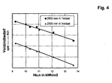
- Suitable parameters for the gas quality detection are the burning rate, the air requirement or the calorific value of the fuel gas or the fuel gas / air mixture.
- the burning speed and the air requirement can not be measured directly or only with great effort.
- on-board diagnostic (OBD) systems To monitor the function of the components with regard to legal emission requirements, motor vehicles must be equipped with so-called on-board diagnostic (OBD) systems. Monitoring based on direct emission measurement would require the use of expensive measurement equipment. In addition, for natural gas vehicles, the realization of a corresponding system due to the possible gas quality changes, only possible if a reliable gas quality detection is ensured. As a result, such on-board diagnostic (OBD) systems will be relatively expensive, sophisticated, and therefore expensive.
- the invention has for its object to achieve a simple way optimal combustion in a gas combustion device in terms of legal emission requirements and optimum efficiency with changing gas properties.
- the invention is based on the finding that a gas quality change can be determined cost-effectively from the simple measurement-based detection of the gas-air ratio, preferably by means of measurements of the O 2 or CO 2 content in the exhaust gas.
- a change in the gas quality can be detected immediately in a simple manner and a correction signal can be generated.
- the effect is used that the gas-air ratio ⁇ changes in a change in the gas condition, the calorific value of the gas according to Fig. 2 correlated.
- the correction signal is derived from the maximum signal change before the intervention of the regulation for the gas / air ratio ⁇ . Since the gas-air ratio ⁇ changes very rapidly in the event of a gas exchange, and indeed before a possibly existing ⁇ control can intervene in a corrective manner, disturbing influences due to the ⁇ control can be neglected. With the aid of the correction signal, the gas-air ratio can be adapted to the setpoint very quickly, which avoids increased emissions that occur during the adaptation period.
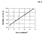
- the first probe additionally measures the CO 2max content in the exhaust gas at a gas / air ratio ⁇ of substantially 1.
- the measuring signal is not influenced by operating parameters, but depends exclusively on the nature of the gas.
- the correction signal generated in the evaluation unit is supplied to a control unit and used as a pilot signal for adjusting the gas and / or air volume flow, usually the gas volume flow.
- the engine speed, load and combustion air temperature are read out of the control unit and fed to the evaluation unit for adjusting the correction signal in response to different operating and environmental conditions.
- the measured values of a probe for measuring the gas-air ratio are also evaluated for emission monitoring. It may be incinerators for liquid or gaseous fuels.
- the measured values of the first probe are compared with setpoints that are stored in the evaluation unit. If a measured value deviates from the nominal value over a predetermined period of time and over a predetermined difference, there is a control-related disturbance of the pollutant reduction system and a warning or error signal is issued or the gas combustion device is switched off.
- the exhaust gas temperatures upstream and downstream of the pollutant reduction system can be measured and compared in the evaluation unit with at least one target value. Will be a predetermined difference exceeded between setpoint and measured value, a warning signal is issued or switched off the gas combustion device.
- the difference between the two measured temperatures is compared with a predetermined desired value over a predetermined period of time. If the difference in the measured values over the given period of time is less than the setpoint value, this is a signal that the functionality of the pollutant reduction system is limited. A warning signal is issued or the gas combustion device is switched off.
- a second probe for metrological detection of the gas-air ratio, preferably for measuring the O 2 or CO content. If the difference between the two ⁇ values resulting from the measured values changes compared to a specified setpoint value, this is a signal that the first probe is damaged or aged.
- the measured values of the first and the second probe are compared with reference values as a function of operating parameters such as rotational speed, torque, air temperature or the like. If the measured values change beyond a predefined setpoint value over a predetermined period of time, this is a signal for a defect in the regulation of the gas combustion device.
- a NO x probe measures the NO x content in the exhaust gas downstream of the pollutant reduction plant.
- the measured values are also fed to the evaluation unit and evaluated.
- a first probe 6 for measuring the O 2 content and a temperature sensor 7 are arranged in the exhaust gas line 2.
- a second probe 8 for measuring the O 2 content, a second temperature sensor 9 and a NOx sensor 10 are arranged in the exhaust gas flow. The signals of the probes and temperature sensors are fed to an electronic evaluation unit 11.
- the first probe 6 continuously measures the oxygen content in the exhaust gas.
- the measured values are fed to a control unit 12, which regulates the gas-air ratio ( ⁇ ) of the gas-air mixture as a function of a desired value.
- the measured values are additionally supplied to an electronic evaluation unit 11. From the measurement signals, namely voltage signals is determined by the correlation according to Fig. 2 a the Brennwert -°. generated the Wobbeiere analog correction signal.
- the correction signal is supplied to the control unit 12. In the control unit 12 is corrected with the correction signal stored in the control unit ignition timing map. In addition, the correction signal is used in the control unit as a pilot signal for adjusting the gas or air flow rate. Alternatively, the changes could also be made in the evaluation unit 11.
- the feedforward control causes the gas-air ratio to be adjusted very quickly to the setpoint value after a gas change acts. This avoids increased emissions that occur during the adaptation period.
- the first probe 6 operates in a wide measuring range.
- a separate suitable probe shall be used for the measurement for the purpose of detecting changes in gas quality.
- these data are read from the control unit 12 and fed to the evaluation unit 11. There, if necessary, the correction signal is adjusted.
- the combustion device In a control-related disturbance of the pollutant reduction system, the combustion device is no longer operated in the intended air range (for example, in a 3-way catalyst outside the so-called lambda window). Depending on whether this is a change in the direction of "rich” or “lean” mixture, the O 2 value, measured continuously with the aid of the first probe 6, increases or decreases.
- the combustion device When the first probe has aged, the combustion device is also no longer operated in the intended air range and the measured O 2 value changes.
- the current measured value is compared with setpoints that are stored in the transmitter 11. If the measured value deviates too much from the setpoint value over a specified permissible time, an error message will be issued. Alternatively, the combustion device can be switched off.
- the permissible period for the deviation is stored via the evaluation unit.
- An increase in emissions may also be the result of an aging-related disturbance on the catalyst body.
- the exhaust gas temperatures are measured by means of the temperature sensors 7, 9 and compared with setpoints that are stored in the transmitter 11. Excessive deviations will result in a warning or shutdown.
- a thermal or mechanical damage or poisoning of the catalyst body also leads to a lower chemical activity and is treated analogously.
- NO x sensor 10 With the help of the NO x sensor 10, an increase in nitrogen oxide emissions can be detected directly.
- An NO x sensor is required if in addition the function of NO x -selective pollution control systems, eg. B. of NO x storage catalysts to be monitored, since this is not ensured solely by the evaluation of the temperatures in the exhaust gas.
- emissions increases may be caused by aging, damage or poisoning of the 3-way catalyst, by damage or aging of the O 2 sensor, by a control error, by a change in gas quality, or by changing engine operating parameters.
- the increase in emissions is based on a change in the 3-way catalytic converter when the difference between the measured values of the temperature sensors 7, 9 installed upstream and downstream of the pollutant reduction system 3, over a longer period at reference operating parameters (speed, torque, air intake temperature, etc.). smaller than setpoint values stored in the evaluation unit. Based on the time course of the temperature change can be determined whether it is a "normal" aging process or acute damage.
- the comparison of the measured and the setpoint values takes place in the evaluation unit 11.
- the engine operating parameters are read out of the control unit 12.
- the period of time that defines when it is a matter of a short-term change in the signals due to changing operating conditions or long-term changes due to undesirable changes, can be specified depending on the behavior of the engine or the lambda control.
- the causes of the emission increases are derived from exhaust gas values which can be measured in a comparatively simple and cost-effective manner (exhaust-gas temperatures, O 2 or CO 2 values and the signal of an NO x sensor).
- the method can be used flexibly. Depending on requirements, it can also be used exclusively for emission control or gas quality detection. Instead of O 2 or CO 2 probes any suitable probes for metrological detection of the gas-air ratio in the exhaust gas can be used.
Landscapes
- Engineering & Computer Science (AREA)
- Chemical & Material Sciences (AREA)
- Combustion & Propulsion (AREA)
- Mechanical Engineering (AREA)
- General Engineering & Computer Science (AREA)
- Exhaust Gas After Treatment (AREA)
- Feeding And Controlling Fuel (AREA)
- Incineration Of Waste (AREA)
Claims (13)
- Procédé pour la surveillance de la combustion dans une installation conçue sous forme de moteur à allumage par étincelle, destinée à la combustion de gaz, en particulier de gaz naturel, où est saisi par mesurage, à l'aide d'un premier capteur, le rapport air/gaz dans les fumées et où sont acheminées les valeurs de mesure à une unité de commande qui règle, en fonction d'une valeur de consigne, le rapport air/gaz,
caractérisé par le fait
que les valeurs de mesure du premier capteur sont en outre acheminées à une unité d'exploitation de données, que, en cas d'un changement de la qualité de gaz et avant la correction du rapport air/gaz, est déduit dans l'unité d'exploitation de données à partir du changement maximal des valeurs de mesure, à l'aide d'une corrélation mémorisée, un deuxième signal de correction analogue au pouvoir calorifique supérieur ou à l'indice de Wobbe, et que le signal de correction est acheminé à l'unité de commande pour la correction d'un réseau de caractéristiques des moments d'allumage mémorisé dans l'unité de commande. - Procédé suivant la revendication 1,
caractérisé par le fait
que le premier capteur mesure la teneur en O2 ou la teneur en CO2 dans les fumées. - Procédé suivant l'une des revendications 1 ou 2,
caractérisé par le fait
que le premier capteur mesure la teneur en CO2max dans les fumées pour un rapport air/gaz λ substantiellement 1, et que dans l'unité d'exploitation de données est généré, moyennant une deuxième corrélation, un signal de correction analogue au pouvoir calorifique supérieur ou à l'indice de Wobbe. - Procédé suivant l'une des revendications 1 à 3,
caractérisé par le fait
que le signal de correction est utilisé comme signal de préréglage pour l'ajustage du débit volumique de gaz et/ou du débit volumique de l'air. - Procédé suivant l'une des revendications 1 à 4,
caractérisé par le fait que sont triés de l'unité de commande le nombre de tours du moteur, la charge et la température de l'air comburant et acheminés à l'unité d'exploitation de données pour l'adaptation du signal de correction en fonction de différentes conditions d'exploitation et environnementales. - Procédé suivant l'une des revendications 1 à 5,
où l'installation de combustion de gaz est dotée d'une installation de réduction des matières polluantes pour le post-traitement des fumées,
caractérisé par le fait
que les valeurs de mesure du rapport gaz/air saisies par mesurage sont comparées, dans l'unité d'exploitation de données, avec au moins une valeur de consigne et qu'un signal d'alarme ou d'erreur est émis ou l'installation de combustion arrêtée, quand une valeur de mesure présente un écart par rapport à la valeur de consigne sur un chiffre et pendant une durée prédéterminés. - Procédé suivant la revendication 6,
caractérisé par le fait
que les températures des fumées sont mesurées en amont et en aval de l'installation de réduction des matières polluantes, que les valeurs de mesure sont acheminées à l'unité d'exploitation de données et comparées avec au moins une valeur de consigne, et qu'un signal d'alarme est émis ou l'installation de combustion arrêtée, quand au moins une valeur de mesure présente un écart par rapport à la valeur de consigne sur un chiffre prédéterminé. - Procédé suivant la revendication 7,
caractérisé par le fait que la différence des deux valeurs de température est formée, que la différence est comparée avec une valeur de consigne et qu'un signal d'alarme est émis ou l'installation de combustion arrêtée, quand la différence présente un écart par rapport à la valeur de consigne sur un chiffre prédéterminé ou quand la différence est inférieure à la valeur de consigne pendant une période prédéterminée. - Procédé suivant l'une des revendications 7 ou 8,
caractérisé par le fait
que la différence des deux valeurs de température est comparée avec des valeurs de consigne pendant une période prédéterminée sous des paramètres de référence prédéterminés. - Procédé suivant l'une des revendications 6 à 9,
caractérisé par le fait
que le rapport gaz/air dans les fumées est saisi par mesurage, à l'aide d'un deuxième capteur, en aval de l'installation de réduction des matières polluantes, que les valeurs de mesure du deuxième capteur sont comparées avec les valeurs de mesure du premier capteur, et qu'un signal d'alarme est émis ou l'installation de combustion arrêtée, quand la différence des deux valeurs de mesure dépasse une valeur de consigne. - Procédé suivant la revendication 10,
caractérisé par le fait que
le deuxième capteur mesure la teneur en O2 ou la teneur en CO2 dans les fumées. - Procédé suivant l'une des revendications 10 ou 11,
caractérisé par le fait que des valeurs de mesure des capteurs sont comparées, pendant une période prédéterminée, avec des valeurs de référence à des paramètres d'exploitation prédéterminés. - Procédé suivant l'une des revendications 1 à 12,
caractérisé par le fait qu'un troisième capteur mesure la teneur en NOx dans les fumées en aval de l'installation de réduction des matières polluantes, que les valeurs de mesure sont acheminées à l'unité d'exploitation de données et comparée avec une valeur de consigne, et qu'un signal d'alarme est émis ou l'installation de combustion arrêtée, quand une valeur de mesure présente un écart par rapport à la valeur de consigne sur un chiffre prédéterminé.
Applications Claiming Priority (2)
| Application Number | Priority Date | Filing Date | Title |
|---|---|---|---|
| DE10316994 | 2003-04-11 | ||
| DE10316994A DE10316994A1 (de) | 2003-04-11 | 2003-04-11 | Verfahren zum Überwachen der Verbrennung in einer Verbrennungseinrichtung |
Publications (2)
| Publication Number | Publication Date |
|---|---|
| EP1467149A1 EP1467149A1 (fr) | 2004-10-13 |
| EP1467149B1 true EP1467149B1 (fr) | 2010-12-15 |
Family
ID=32864475
Family Applications (1)
| Application Number | Title | Priority Date | Filing Date |
|---|---|---|---|
| EP04007876A Expired - Lifetime EP1467149B1 (fr) | 2003-04-11 | 2004-04-01 | Méthode pour surveiller la combustion dans un dispositif de combustion |
Country Status (3)
| Country | Link |
|---|---|
| EP (1) | EP1467149B1 (fr) |
| AT (1) | ATE491915T1 (fr) |
| DE (2) | DE10316994A1 (fr) |
Families Citing this family (11)
| Publication number | Priority date | Publication date | Assignee | Title |
|---|---|---|---|---|
| EP1522790B1 (fr) | 2003-10-08 | 2011-11-23 | Vaillant GmbH | Procédé de régulation d'un brûleur à gaz, en particulier dans des installations de chauffe avec ventilateur |
| DE102010044430A1 (de) | 2010-09-04 | 2012-03-08 | G I W E P Gesellschaft für industrielle Wärme, Energie- und Prozeßtechnik m.b.H | Verfahren zur Überwachung von gasbeheizten Ofenanlagen |
| CN106468446B (zh) * | 2016-08-31 | 2020-10-13 | 西安艾贝尔科技发展有限公司 | 一种加热炉控制与燃烧优化方法 |
| DE102016218794A1 (de) * | 2016-09-29 | 2018-03-29 | Robert Bosch Gmbh | Stationärer Erdgasmotor mit wenigstens einem Stickoxidsensor |
| DE102020119960B4 (de) * | 2020-07-29 | 2025-11-13 | Man Truck & Bus Se | Ermitteln einer Brenngaszusammensetzung |
| ES2986992T3 (es) | 2021-02-26 | 2024-11-13 | Siemens Ag | Procedimiento para regular un dispositivo de quemador con determinación de potencia mediante un parámetro de combustible |
| CN116792759B (zh) * | 2023-07-06 | 2024-02-02 | 碎得机械(北京)有限公司 | 一种危废预处理系统的控制方法、装置及系统 |
| DE102023212455B3 (de) * | 2023-11-30 | 2024-12-24 | Siemens Aktiengesellschaft | Automatisierung anhand Sauerstoffkonzentration |
| WO2025168719A1 (fr) * | 2024-02-06 | 2025-08-14 | BDR Thermea Group B.V | Procédé de fonctionnement d'un appareil de combustion dans un mode de mise en service de l'appareil de combustion |
| EP4600555A1 (fr) * | 2024-02-06 | 2025-08-13 | BDR Thermea Group B.V. | Procédé de fonctionnement d'au moins un appareil de combustion, notamment adaptatif au gaz |
| EP4617566A1 (fr) | 2024-03-11 | 2025-09-17 | Siemens Aktiengesellschaft | Commande optimisée d'un dispositif de combustion |
Family Cites Families (11)
| Publication number | Priority date | Publication date | Assignee | Title |
|---|---|---|---|---|
| DE2713988A1 (de) * | 1977-03-30 | 1978-10-05 | Bosch Gmbh Robert | Verfahren und einrichtung zur bestimmung der verhaeltnisanteile des einer brennkraftmaschine zugefuehrten kraftstoff-luftgemisches |
| DE3526384A1 (de) * | 1985-07-24 | 1987-02-12 | Bieler & Lang Gmbh | Verfahren und anordnung zur feinregulierung des brennstoffmengenstromes an brennerbetriebenen feuerungsanlagen durch messung des restsauerstoffes und des kohlenmonoxidgehaltes in den abgasen |
| DE3614535A1 (de) * | 1986-04-29 | 1987-11-05 | Comuna Metall Vorrichtungs U M | Abgasgereinigte brennkraftmaschine |
| DE3827978A1 (de) * | 1987-11-10 | 1989-05-18 | Bosch Gmbh Robert | Verfahren und vorrichtung fuer stetige lambdaregelung |
| FR2628827B1 (fr) * | 1988-03-21 | 1990-07-06 | Haan Andre | Procede pour optimiser une combustion, dispositif pour la mise en oeuvre de ce procede, ainsi que detecteur equipant un tel dispositif |
| DE4001616C2 (de) * | 1990-01-20 | 1998-12-10 | Bosch Gmbh Robert | Verfahren und Vorrichtung zur Kraftstoffmengenregelung für eine Brennkraftmaschine mit Katalysator |
| DE19611110A1 (de) * | 1996-03-21 | 1997-10-23 | Poetters Zita | Verfahren zur Optimierung von Verbrennungsprozessen |
| DE19733575A1 (de) * | 1997-08-02 | 1999-02-04 | Mannesmann Vdo Ag | Vorsteuerwertekorrektur bei Brennkraftmaschinen |
| DE10001251B4 (de) * | 2000-01-14 | 2005-01-27 | Robert Bosch Gmbh | Verfahren zum Steuern oder Regeln eines Gasbrenners |
| DE10111077C2 (de) * | 2001-03-08 | 2003-11-06 | Bosch Gmbh Robert | Verfahren zum Regeln eines Brenners eines Gasverbrennungsgeräts |
| AT411189B (de) * | 2002-01-17 | 2003-10-27 | Vaillant Gmbh | Verfahren zur regelung eines gasbrenners |
-
2003
- 2003-04-11 DE DE10316994A patent/DE10316994A1/de not_active Ceased
-
2004
- 2004-04-01 AT AT04007876T patent/ATE491915T1/de active
- 2004-04-01 EP EP04007876A patent/EP1467149B1/fr not_active Expired - Lifetime
- 2004-04-01 DE DE502004011983T patent/DE502004011983D1/de not_active Expired - Lifetime
Also Published As
| Publication number | Publication date |
|---|---|
| DE10316994A1 (de) | 2004-10-28 |
| EP1467149A1 (fr) | 2004-10-13 |
| DE502004011983D1 (de) | 2011-01-27 |
| ATE491915T1 (de) | 2011-01-15 |
Similar Documents
| Publication | Publication Date | Title |
|---|---|---|
| DE3500594C2 (de) | Zumeßsystem für eine Brennkraftmaschine zur Beeinflussung des Betriebsgemisches | |
| EP1327138B1 (fr) | Procede et dispositif d'autodiagnostic d'un capteur de nox | |
| DE102017218327B4 (de) | Verfahren zum Betreiben einer Brennkraftmaschine mit Dreiwegekatalysator und Lambdaregelung | |
| EP1467149B1 (fr) | Méthode pour surveiller la combustion dans un dispositif de combustion | |
| DE10111586A1 (de) | Verfahren zum Betrieb von Brennkraftmaschinen | |
| DE10319983B3 (de) | Verfahren und Vorrichtung zur Lambda-Regelung und zur Katalysatordiagnose bei einer Brennkraftmaschine | |
| EP3686404A1 (fr) | Dispositif et procédé de post-traitement des gaz d'échappement d'un moteur à combustion interne | |
| DE19811574A1 (de) | Verfahren und Vorrichtung zum Überwachen der Funktionsfähigkeit eines Katalysators einer Brennkraftmaschine | |
| WO2001004471A1 (fr) | Procede pour la verification d'un pot d'echappement catalytique a trois voies d'un moteur a combustion interne | |
| EP3680461A1 (fr) | Système d'air de régénération pour un système de traitement des gaz d'échappement d'un moteur à combustion interne et procédé de traitement des gaz d'échappement | |
| DE10130054B4 (de) | Abgasanlage einer mehrzylindrigen Verbrennungskraftmaschine und Verfahren zur Reinigung eines Abgases | |
| DE10309422B4 (de) | Verfahren und Vorrichtung zur Kalibrierung eines NOx-Sensors | |
| DE10014881B4 (de) | Vorrichtung und Verfahren zur Kalibrierung von Lambdasonden | |
| EP1136670B1 (fr) | Dispositif et procédé de surveillance d'un catalyseur à trois voies dans le pot d'échappement d'un moteur à combustion interne | |
| EP4545762B1 (fr) | Procédé de fonctionnement d'un dispositif d'entraînement pour un véhicule automobile, dispositif d'entraînement pour un véhicule automobile ainsi que produit programme informatique | |
| DE10160704A1 (de) | Verfahren zum Betrieb von Abgasreinigungsvorrichtungen | |
| WO1999056012A1 (fr) | Procede d'epuration de gaz residuaires a reglage de precision | |
| EP0655583B1 (fr) | Procédé pour le réglage et la surveillance de combustion | |
| KR100225308B1 (ko) | 내연기관의 배기가스내로 공기를 분사하기 위한 장치의 시험방법 | |
| WO2020221540A1 (fr) | Réduction d'oxydes d'azote dans le flux de gaz d'échappement d'une installation de calcination avec un catalyseur scr | |
| DE102021125353B3 (de) | Verfahren zum Betreiben einer Antriebseinrichtung sowie entsprechende Antriebseinrichtung | |
| EP1244871B1 (fr) | Dispositif et procede pour commander la vitesse de reinjection de gaz d'echappement d'un dispositif de reinjection de gaz d'echappement pour moteurs a combustion interne pendant le fonctionnement en mode melange pauvre | |
| WO2000025011A1 (fr) | Procede et dispositif permettant de diagnostiquer un recyclage des gaz d'echappement d'un processus de combustion | |
| DE102010030635B4 (de) | Verfahren und Vorrichtung zur Aufheizung eines Katalysators zur Abgasreinigung | |
| DE10223385B4 (de) | Verfahren und Vorrichtung zur Steuerung eines Sensors |
Legal Events
| Date | Code | Title | Description |
|---|---|---|---|
| PUAI | Public reference made under article 153(3) epc to a published international application that has entered the european phase |
Free format text: ORIGINAL CODE: 0009012 |
|
| AK | Designated contracting states |
Kind code of ref document: A1 Designated state(s): AT BE BG CH CY CZ DE DK EE ES FI FR GB GR HU IE IT LI LU MC NL PL PT RO SE SI SK TR |
|
| AX | Request for extension of the european patent |
Extension state: AL HR LT LV MK |
|
| 17P | Request for examination filed |
Effective date: 20050114 |
|
| AKX | Designation fees paid |
Designated state(s): AT BE BG CH CY CZ DE DK EE ES FI FR GB GR HU IE IT LI LU MC NL PL PT RO SE SI SK TR |
|
| 17Q | First examination report despatched |
Effective date: 20060725 |
|
| GRAP | Despatch of communication of intention to grant a patent |
Free format text: ORIGINAL CODE: EPIDOSNIGR1 |
|
| GRAS | Grant fee paid |
Free format text: ORIGINAL CODE: EPIDOSNIGR3 |
|
| GRAA | (expected) grant |
Free format text: ORIGINAL CODE: 0009210 |
|
| AK | Designated contracting states |
Kind code of ref document: B1 Designated state(s): AT BE BG CH CY CZ DE DK EE ES FI FR GB GR HU IE IT LI LU MC NL PL PT RO SE SI SK TR |
|
| REG | Reference to a national code |
Ref country code: GB Ref legal event code: FG4D Free format text: NOT ENGLISH Ref country code: CH Ref legal event code: EP |
|
| REG | Reference to a national code |
Ref country code: IE Ref legal event code: FG4D |
|
| REF | Corresponds to: |
Ref document number: 502004011983 Country of ref document: DE Date of ref document: 20110127 Kind code of ref document: P |
|
| REG | Reference to a national code |
Ref country code: NL Ref legal event code: T3 |
|
| PG25 | Lapsed in a contracting state [announced via postgrant information from national office to epo] |
Ref country code: BG Free format text: LAPSE BECAUSE OF FAILURE TO SUBMIT A TRANSLATION OF THE DESCRIPTION OR TO PAY THE FEE WITHIN THE PRESCRIBED TIME-LIMIT Effective date: 20110315 Ref country code: FI Free format text: LAPSE BECAUSE OF FAILURE TO SUBMIT A TRANSLATION OF THE DESCRIPTION OR TO PAY THE FEE WITHIN THE PRESCRIBED TIME-LIMIT Effective date: 20101215 Ref country code: CY Free format text: LAPSE BECAUSE OF FAILURE TO SUBMIT A TRANSLATION OF THE DESCRIPTION OR TO PAY THE FEE WITHIN THE PRESCRIBED TIME-LIMIT Effective date: 20101215 Ref country code: SE Free format text: LAPSE BECAUSE OF FAILURE TO SUBMIT A TRANSLATION OF THE DESCRIPTION OR TO PAY THE FEE WITHIN THE PRESCRIBED TIME-LIMIT Effective date: 20101215 Ref country code: SI Free format text: LAPSE BECAUSE OF FAILURE TO SUBMIT A TRANSLATION OF THE DESCRIPTION OR TO PAY THE FEE WITHIN THE PRESCRIBED TIME-LIMIT Effective date: 20101215 |
|
| REG | Reference to a national code |
Ref country code: IE Ref legal event code: FD4D |
|
| PG25 | Lapsed in a contracting state [announced via postgrant information from national office to epo] |
Ref country code: ES Free format text: LAPSE BECAUSE OF FAILURE TO SUBMIT A TRANSLATION OF THE DESCRIPTION OR TO PAY THE FEE WITHIN THE PRESCRIBED TIME-LIMIT Effective date: 20110326 Ref country code: PT Free format text: LAPSE BECAUSE OF FAILURE TO SUBMIT A TRANSLATION OF THE DESCRIPTION OR TO PAY THE FEE WITHIN THE PRESCRIBED TIME-LIMIT Effective date: 20110415 Ref country code: GR Free format text: LAPSE BECAUSE OF FAILURE TO SUBMIT A TRANSLATION OF THE DESCRIPTION OR TO PAY THE FEE WITHIN THE PRESCRIBED TIME-LIMIT Effective date: 20110316 Ref country code: EE Free format text: LAPSE BECAUSE OF FAILURE TO SUBMIT A TRANSLATION OF THE DESCRIPTION OR TO PAY THE FEE WITHIN THE PRESCRIBED TIME-LIMIT Effective date: 20101215 Ref country code: CZ Free format text: LAPSE BECAUSE OF FAILURE TO SUBMIT A TRANSLATION OF THE DESCRIPTION OR TO PAY THE FEE WITHIN THE PRESCRIBED TIME-LIMIT Effective date: 20101215 Ref country code: IE Free format text: LAPSE BECAUSE OF FAILURE TO SUBMIT A TRANSLATION OF THE DESCRIPTION OR TO PAY THE FEE WITHIN THE PRESCRIBED TIME-LIMIT Effective date: 20101215 |
|
| PG25 | Lapsed in a contracting state [announced via postgrant information from national office to epo] |
Ref country code: SK Free format text: LAPSE BECAUSE OF FAILURE TO SUBMIT A TRANSLATION OF THE DESCRIPTION OR TO PAY THE FEE WITHIN THE PRESCRIBED TIME-LIMIT Effective date: 20101215 Ref country code: RO Free format text: LAPSE BECAUSE OF FAILURE TO SUBMIT A TRANSLATION OF THE DESCRIPTION OR TO PAY THE FEE WITHIN THE PRESCRIBED TIME-LIMIT Effective date: 20101215 Ref country code: PL Free format text: LAPSE BECAUSE OF FAILURE TO SUBMIT A TRANSLATION OF THE DESCRIPTION OR TO PAY THE FEE WITHIN THE PRESCRIBED TIME-LIMIT Effective date: 20101215 |
|
| PLBE | No opposition filed within time limit |
Free format text: ORIGINAL CODE: 0009261 |
|
| STAA | Information on the status of an ep patent application or granted ep patent |
Free format text: STATUS: NO OPPOSITION FILED WITHIN TIME LIMIT |
|
| PG25 | Lapsed in a contracting state [announced via postgrant information from national office to epo] |
Ref country code: DK Free format text: LAPSE BECAUSE OF FAILURE TO SUBMIT A TRANSLATION OF THE DESCRIPTION OR TO PAY THE FEE WITHIN THE PRESCRIBED TIME-LIMIT Effective date: 20101215 |
|
| 26N | No opposition filed |
Effective date: 20110916 |
|
| PG25 | Lapsed in a contracting state [announced via postgrant information from national office to epo] |
Ref country code: MC Free format text: LAPSE BECAUSE OF NON-PAYMENT OF DUE FEES Effective date: 20110430 |
|
| PG25 | Lapsed in a contracting state [announced via postgrant information from national office to epo] |
Ref country code: IT Free format text: LAPSE BECAUSE OF FAILURE TO SUBMIT A TRANSLATION OF THE DESCRIPTION OR TO PAY THE FEE WITHIN THE PRESCRIBED TIME-LIMIT Effective date: 20101215 |
|
| REG | Reference to a national code |
Ref country code: DE Ref legal event code: R097 Ref document number: 502004011983 Country of ref document: DE Effective date: 20110916 |
|
| PGFP | Annual fee paid to national office [announced via postgrant information from national office to epo] |
Ref country code: LU Payment date: 20120426 Year of fee payment: 9 Ref country code: BE Payment date: 20120418 Year of fee payment: 9 Ref country code: CH Payment date: 20120420 Year of fee payment: 9 |
|
| PGFP | Annual fee paid to national office [announced via postgrant information from national office to epo] |
Ref country code: FR Payment date: 20120507 Year of fee payment: 9 |
|
| PGFP | Annual fee paid to national office [announced via postgrant information from national office to epo] |
Ref country code: AT Payment date: 20120411 Year of fee payment: 9 |
|
| REG | Reference to a national code |
Ref country code: DE Ref legal event code: R081 Ref document number: 502004011983 Country of ref document: DE Owner name: E.ON NEW BUILD & TECHNOLOGY GMBH, DE Free format text: FORMER OWNER: E.ON RUHRGAS AG, 45131 ESSEN, DE Effective date: 20130218 |
|
| PG25 | Lapsed in a contracting state [announced via postgrant information from national office to epo] |
Ref country code: TR Free format text: LAPSE BECAUSE OF FAILURE TO SUBMIT A TRANSLATION OF THE DESCRIPTION OR TO PAY THE FEE WITHIN THE PRESCRIBED TIME-LIMIT Effective date: 20101215 |
|
| BERE | Be: lapsed |
Owner name: E.ON RUHRGAS A.G. Effective date: 20130430 |
|
| PG25 | Lapsed in a contracting state [announced via postgrant information from national office to epo] |
Ref country code: HU Free format text: LAPSE BECAUSE OF FAILURE TO SUBMIT A TRANSLATION OF THE DESCRIPTION OR TO PAY THE FEE WITHIN THE PRESCRIBED TIME-LIMIT Effective date: 20101215 |
|
| REG | Reference to a national code |
Ref country code: CH Ref legal event code: PL |
|
| REG | Reference to a national code |
Ref country code: AT Ref legal event code: MM01 Ref document number: 491915 Country of ref document: AT Kind code of ref document: T Effective date: 20130430 |
|
| PG25 | Lapsed in a contracting state [announced via postgrant information from national office to epo] |
Ref country code: CH Free format text: LAPSE BECAUSE OF NON-PAYMENT OF DUE FEES Effective date: 20130430 Ref country code: BE Free format text: LAPSE BECAUSE OF NON-PAYMENT OF DUE FEES Effective date: 20130430 Ref country code: LI Free format text: LAPSE BECAUSE OF NON-PAYMENT OF DUE FEES Effective date: 20130430 Ref country code: AT Free format text: LAPSE BECAUSE OF NON-PAYMENT OF DUE FEES Effective date: 20130430 |
|
| REG | Reference to a national code |
Ref country code: FR Ref legal event code: ST Effective date: 20131231 |
|
| PG25 | Lapsed in a contracting state [announced via postgrant information from national office to epo] |
Ref country code: FR Free format text: LAPSE BECAUSE OF NON-PAYMENT OF DUE FEES Effective date: 20130430 |
|
| PGFP | Annual fee paid to national office [announced via postgrant information from national office to epo] |
Ref country code: NL Payment date: 20150420 Year of fee payment: 12 |
|
| PG25 | Lapsed in a contracting state [announced via postgrant information from national office to epo] |
Ref country code: LU Free format text: LAPSE BECAUSE OF NON-PAYMENT OF DUE FEES Effective date: 20130401 |
|
| PGFP | Annual fee paid to national office [announced via postgrant information from national office to epo] |
Ref country code: DE Payment date: 20150421 Year of fee payment: 12 Ref country code: GB Payment date: 20150420 Year of fee payment: 12 |
|
| REG | Reference to a national code |
Ref country code: DE Ref legal event code: R119 Ref document number: 502004011983 Country of ref document: DE |
|
| REG | Reference to a national code |
Ref country code: NL Ref legal event code: MM Effective date: 20160501 |
|
| GBPC | Gb: european patent ceased through non-payment of renewal fee |
Effective date: 20160401 |
|
| PG25 | Lapsed in a contracting state [announced via postgrant information from national office to epo] |
Ref country code: DE Free format text: LAPSE BECAUSE OF NON-PAYMENT OF DUE FEES Effective date: 20161101 Ref country code: GB Free format text: LAPSE BECAUSE OF NON-PAYMENT OF DUE FEES Effective date: 20160401 Ref country code: NL Free format text: LAPSE BECAUSE OF NON-PAYMENT OF DUE FEES Effective date: 20160501 |