EP1468901A2 - Engin à chenille à voie variable - Google Patents
Engin à chenille à voie variable Download PDFInfo
- Publication number
- EP1468901A2 EP1468901A2 EP04006506A EP04006506A EP1468901A2 EP 1468901 A2 EP1468901 A2 EP 1468901A2 EP 04006506 A EP04006506 A EP 04006506A EP 04006506 A EP04006506 A EP 04006506A EP 1468901 A2 EP1468901 A2 EP 1468901A2
- Authority
- EP
- European Patent Office
- Prior art keywords
- vehicle according
- chassis
- vehicle frame
- vehicle
- receiving
- Prior art date
- Legal status (The legal status is an assumption and is not a legal conclusion. Google has not performed a legal analysis and makes no representation as to the accuracy of the status listed.)
- Granted
Links
- 238000010276 construction Methods 0.000 claims abstract description 8
- 125000006850 spacer group Chemical group 0.000 claims description 32
- 239000002904 solvent Substances 0.000 claims description 3
- 230000018109 developmental process Effects 0.000 description 2
- 230000004323 axial length Effects 0.000 description 1
- 239000003795 chemical substances by application Substances 0.000 description 1
- 238000004519 manufacturing process Methods 0.000 description 1
- 239000000463 material Substances 0.000 description 1
- 238000012986 modification Methods 0.000 description 1
- 230000004048 modification Effects 0.000 description 1
Images


Classifications
-
- B—PERFORMING OPERATIONS; TRANSPORTING
- B62—LAND VEHICLES FOR TRAVELLING OTHERWISE THAN ON RAILS
- B62D—MOTOR VEHICLES; TRAILERS
- B62D49/00—Tractors
- B62D49/06—Tractors adapted for multi-purpose use
- B62D49/0678—Tractors of variable track width or wheel base
-
- B—PERFORMING OPERATIONS; TRANSPORTING
- B62—LAND VEHICLES FOR TRAVELLING OTHERWISE THAN ON RAILS
- B62D—MOTOR VEHICLES; TRAILERS
- B62D55/00—Endless track vehicles
- B62D55/08—Endless track units; Parts thereof
- B62D55/084—Endless-track units or carriages mounted separably, adjustably or extensibly on vehicles, e.g. portable track units
Definitions
- the invention relates to a tracked vehicle with a variable track width, especially as a construction vehicle and / or as a vehicle for agricultural purposes
- a vehicle frame includes, on both sides of a chassis with a chassis carrier for at least one drive wheel, one deflection wheel and one for support wheels is intended for guiding caterpillars.
- the invention is therefore based on the object of providing measures with the help of which it is possible in a technically simple manner and at low cost is to create a tracked vehicle with a variable track width.
- the invention provides with the features of characterizing part of claim 1 that at least one of the two chassis beams at different distances across the undercarriage with the help of holding agents and solvents as well as with the help of laterally Carrying, receiving and supporting means arranged at the front and rear is releasably attachable to the vehicle frame.
- the holding and solvent are preferably bores respectively Through openings and screws and / or for fastening Threaded bolts with possibly assigned nuts.
- Support and support means are on the one hand support arms and on the other hand this receiving and usually largely or partially form-fitting comprehensive receiving parts on the vehicle frame and / or on Chassis beams arranged and aligned with each other.
- the Support arms can be at least partially U-shaped and / or in cross section also be L-shaped and up at their attachment points and / or arranged at the bottom and / or at the rear open cross section his.
- the support and receiving parts also preferably have a U-shaped and / or L-shaped cross section.
- a tracked vehicle consisting only of the upper and lower vehicle can therefore easily according to the embodiment, for example arranged on the chassis beam and freely projecting from it Put on the support arms. Furthermore, both the right and the left undercarriage with its undercarriage along the support arms transverse to Position the vehicle frame and at a desired distance from Vehicle frames and undercarriage using threaded bolts or Fasten screws and nuts.
- each chassis carrier at the same time as a support for a hydraulic and / or an electrical one Drive serves.
- the vehicle drive at least comprises a main motor and that respective drives for the movement the caterpillars can be arranged directly on the chassis carrier itself. Accordingly, a pump or a generator from the main motor driven to the energy for those arranged on the chassis beams To provide drives.
- the individual drives also change their position in the event of a change according to the track width.
- the individual drives are preferred Hydraulic motors and / or electric motors and only act, for example rear drive wheels.
- the invention is not so limited. It can also have front and rear drive wheels, each with integrated Hydraulic or electric motors can be provided.
- the energy supply of the hydraulic and / or electrical drives is straightforward, as it can be done using hoses and / or using electrical lines can be easily adapted to a changed track width can.
- the track width according to a preferred embodiment in Area of a load-bearing axis such as in the area of a swivel axis for the chassis carrier should be adjustable, a removable Spacer be provided.
- the one when changing the track width Work to be carried out is finally when using a spacer minimal for each axis if the distance bushing is in accordance with one preferred embodiment consists of half shells.
- a height adjustment can also be made made between the vehicle frame and the chassis beams become.
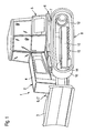
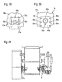
- a chain or caterpillar not shown in the figures agricultural vehicle such as a tractor or a Tractor and similarly as a construction vehicle 2 as shown in Fig. 1 serving caterpillar 1 are each with the required Means for changing the track width equipped and agree in this regard agreed, even if the required funds are only listed below Reference to the construction vehicle 2 shown in FIG. 1 are described. The representations in all figures therefore apply equally to agricultural ones Vehicles and for construction vehicles.
- the crawler vehicle 1 has a tool as the construction vehicle 2 3 for example in the form of a sign or the like on and further includes a vehicle engine 4 and other components of a Upper vehicle 5 and a lower vehicle 6.
- An essential part of the Lower vehicle 6 is a trough-shaped vehicle frame 7 on which A chassis 8 or 9 with a chassis carrier on each side 10, 11 for at least one drive wheel 12, 13 each, for deflection wheels 14 and for support wheels 15 for guiding caterpillars 16 and 17 is provided.
- the drive wheels 12, 13 are gear wheels.
- the vehicle frame 7 includes a right one Side wall 18 and a left side wall 19 and one of these two Side walls 18 and 19 rear side connecting rear wall 20 and one Floor 21.
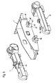
- Both chassis supports 10, 11 are in the exemplary embodiments shown in the figures with their respective components for change the track width releasably connectable to the vehicle frame 7.
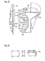
- attachment points 22 and 23 are in the embodiment shown in Fig. 2 formed with the aid of 24, 25 serving as a support Support arms 24 'and 24 "or 25' and 25" on the one hand and from receiving parts 26 'serving as receiving and supporting means 26, 27, 26 "and 27 ', 27" on the other hand, each in alignment on the chassis beams 10, 11 and are arranged on the vehicle frame 7.
- each chassis carrier 10, 11 is in the Cross-section U-shaped and has a support plate 28 'between side parts or 28 ".
- Each freely projecting support arm 24 'or 24 " is expediently welded to the chassis support 10, 11.
- the other or rear support arm 25 ', 25 " can also in Cross section be U-shaped. It is expedient, however, in cross section L-shaped.
- the receiving parts 26 ', 26 "and 27' and 27" are also in cross section U-shaped and / or L-shaped.
- the support arms 24 ', 24 "and 25', 25" and also Receiving parts are each hollow profiles, since at least the rear, at the Drive wheels 12, 13 located support arms 25 ', 25 "preferably one Passage opening 29 (Fig. 3) for lines, not shown, for energy supply of drives 30 and 31, respectively, on the Chassis beams 10, 11 are arranged.
- All support arms 24 ', 24 "and 25', 25” are either to the side of the chassis beams 10, 11 freely cantilevered or at least stand sideways in front. They can be telescoped into the as a receiving and supporting means 26, 27 serving, arranged on the vehicle frame 7, laterally protruding receiving parts 26 ', 26 "and 27', 27” optionally use different amounts according to the desired position and there with the aid of holding and releasing means 32 in the form of bores, Through openings, threaded holes, threaded bolts respectively Securely fix screws and nuts, if any.
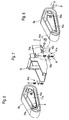
- the respective freely projecting receiving parts 26 ', 26 “and 27' and 27” can be in one piece according to the embodiment and to this the side walls 18, 19 extend into the interior 33 of the vehicle frame 7.
- they can be connected to one another consist of a one-piece profile part 34 or 35, each with free ends through openings 36 (Fig. 2) in extend the side walls 18, 19 to form the receiving parts.
- brackets 37, 38 can be provided to support the load the receiving parts 26 'to 27 "to increase.
- profile part 38 (FIG. 2) is U-shaped in cross section, this applies basically also for the profile part 35. Only its free, as receiving parts 27 ', 27 "serving ends are possibly L-shaped in cross section.
- the profile part 35 also has an interior 33 of the vehicle frame 7 an opening 39. Through them the power supply lines performed, the necessary in the case of hydraulic drives 30, 31 Power supply to pumps that in turn are powered by the vehicle engine 4 are driven as the main motor.
- FIGS. 2 and 3 show some details better than the representations in FIGS. 2 and 3. So this is immediately as a recording and support means 27 serving part angular in cross section and down and towards the rear end 40 of the vehicle frame 7 open. It consists of a vertical leg 41 and another leg 40 "which extends from the upper end 40 '" of the first Leg 40 'horizontally in a direction toward the rear end 40 of the Vehicle frame 7 extends.
- the track width change can therefore be very much with enough play easy to carry out, even if the front support and support means 26 on the vehicle frame 7, the associated support means 24 on the chassis beams 10, 11 positively or almost positively. Nevertheless, the chassis beams 10, 11 are due to the L-shaped design the receiving and supporting means 27 is able to withstand the occurring Forces in the direction of travel fully on the vehicle frame 7 transferred to.
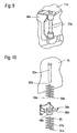
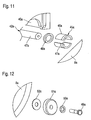
- FIG. 6 to 8 show a right and a left chassis 8a and 9a and a vehicle frame 7a of a modified embodiment, like parts basically the same reference numbers as the first Embodiment and additionally have the letter index a.
- the attachment and storage of the two trolleys 8a and 9a on the vehicle frame 7a is pivotable and in the rear area in the front area with the aid of spring devices 41a.
- For the pivotable bearings are on each side of the vehicle as a support means 24a Cross section of round support arm or an axis 42a (pivot axis) provided. In the assembled state, they each lie in a corresponding one Bore 43a in each of the two chassis supports 10a and 11a.
- the axles 42a are on the vehicle frame 7a by means of a cross section e.g. rectangular intermediate piece 44a rigidly attached.
- the chassis carrier 10a and 11a on the axles 42a also serves each a spacer 45a.
- the spacer bush 45a consists of two half shells 46a and 47a. You can therefore be placed on the axis 42a or can be removed from this without the entire chassis 8a or 9a must be completely withdrawn from the axis 42a.
- the spacer bush 45a is on the axis 42a either on the frame side (large track width) or in the area of the outer end 47a of the axis 42a to achieve a small track width (Fig. 11). This results in the position of the chassis 8a and 9a two different positions for the track width.
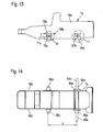
- spring device 41a That at the front end 53a of the vehicle frame 7a on both sides provided spring device 41a comprises, as shown in FIG. 6, chassis side a bracket 54a, on which a support rod 55a at both ends is arranged.
- the holding rod 55a is used to fix two coil springs in the correct position 56a and 57a.
- the holding rod 55a engages in the assembled Condition the two springs 56a and 57a and also a carrying and Guide bracket 58a, the guide sleeve 59a for the support rod 55a.
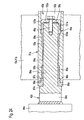
- the two mutually facing ends 64a and 65a of the two springs 56a and 57a are in the assembled state on a holding plate 66a of the carrying and guide console 58a, in which the guide sleeve 59a (Fig. 10 or Fig. 21).
- the carrying guide brackets 58a are basically on the outside of the Vehicle frame 7a or frame side attached or screwed (Fig. 7 or 13 and 14).
- the spacer 67a is H-shaped in cross section according to the exemplary embodiment and consists in one piece of a centrally arranged Block and two plates aligned on this with fastening openings.
- the spacer sleeves 45a are each close to the side walls 18a and 19a of the vehicle frame 7a, as shown in FIG. 25, it is understood that the support and guide brackets 58a are used of spacers 67a outside on the side walls 18a and 19a of the vehicle frame 7a must be attached. The same goes 21 and 22.
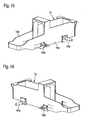
- FIG. 13 to 20 also show various mounting options for the axes 42a and for the support and guide brackets 58a each on the side walls 18a and 19a of the vehicle frame 7a.
- the wearing and Guide bracket 58a in sufficient number of holes 70a for fastening screws on.
- Corresponding bores 71a which are simple holes or elongated holes are located in the side walls 18a and 19a. Specifically, such bores 71a are shown in A larger number is provided such that the support and guide consoles 58a not only at a single, predefined location on the vehicle frame 7a can be attached, but in several places in different distance from the axis 42a and at different Height level.
- the two side walls 18a and 19a therefore have significantly more holes 71a or elongated holes 71a as for a single, positionally accurate attachment the support and guide brackets 58a would be required.
- This intermediate piece 44a can be square in cross-section or also according to that in FIG. 13 and 15 and 20 shown intermediate pieces 44a different from the square shape be rectangular.
- the respective axis is located here 42a on the intermediate piece 44a in an off-center attached position.
- the intermediate pieces 44a have several according to FIGS. 13, 15 and 20 Bores 80a and corresponding bores shown in FIG. 20 lie under the intermediate piece 44a, are located in the side walls 18a and 19a of the vehicle frame 7a, so that the intermediate pieces 44a with their axes 42a in an appropriate manner with the help of also not shown Screws on the side walls 18a and 19a of the vehicle frame 7a can be attached.
- the intermediate pieces 44a in one order 180 degrees rotated position attached to the side walls 18a and 19a.
- the bores 81a now lie in place of the upper bores 80a 20 above (not shown).
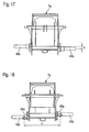
- the axis 42a thereby receives a lower position, as can be seen from a comparison of FIGS. 15 and 16 emerges or can also be seen from FIGS. 17 and 18.
- chassis supports 10a and 10b 11a it is not only possible to adjust the distance between the chassis supports 10a and 10b 11a to change the vehicle frame 7 or 7a, but it can also an arrangement of the chassis beams and 10 or 11 or 10a and 11a at different height levels both in the area of the axes 42a and can also be achieved in the area of the spring devices 41a.
- a caterpillar vehicle according to the exemplary embodiments shown in the figures thus not only has the possibility of changing the track width (distance c according to FIG. 18), but also the distance a (FIG. 14) of the axles 42a from the carrying and guide brackets 58a the spring device 41a can be adjusted. Finally, the position or the level of the axes 42a on the vehicle frame 7a can also be changed in accordance with the distance b according to FIG. 17. The same applies to the height level of the support and guide brackets 58a.
- the spacer bushes 45a and the spacers 67a according to FIGS. 21 to 23 serve to change the track width according to the distance c in FIG. 18.
- the distances a and b are achieved with the aid of additionally provided bores either in the side walls 18a and 19a or in the intermediate pieces 44a ,
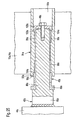
- FIGS. 24 and 25 show in part the section as the support arm and serving as the pivot axis 42a, for example on the intermediate piece 44a welded for attachment to the vehicle frame 7a (Fig. 13) is.
- the axis 42a points in the area of its attachment point serving as a stop axle piece 85a with a larger diameter than the rest of the axis 42a to its free end 86a.
- On a right angle Paragraph 87a the axle piece 85a goes into the axle piece 88a with the smaller diameter over.
- 87a is one with the Axle piece 88a with the same diameter sleeve 89a and engages with one annular projection 90a in a support sleeve 91a.
- One each Carrying sleeve 91a is arranged in each chassis carrier 10a and 11a has a bore 43a, which is also shown in FIGS. 6 and 8.
- the outer circumference of the carrying sleeve 91a is cylindrical, as shown in Figs. 24 and 25.
- each of the support sleeves 91a is stepped down several times.
- a first large diameter bore piece 92a closes a bore piece 93a with a smaller diameter and a middle bore piece 94a, then towards the paragraph 87a again a bore piece 95a with a diameter like the bore piece 93a and finally a relatively short bore piece 96a Connect an inner diameter like the bore piece 92a.
- the annular projection 90a lies in the short bore piece 96a Sleeve 89a with a small track width setting according to FIG. 24. Further located in this case there is an annular air gap 97a between the annular projection 90a and the inner contour of the short bore piece 96a.
- the two bore pieces 93a and 95a each serve to receive short bearing sleeves 98a and 99a, each with a low material thickness.
- the spacer bush 45a In the case of the small track width setting there is in the bore piece 92a the spacer bush 45a. It sits on the free end 86a the axis 42a and according to the embodiment has a one-piece design an axially inner ring piece 100a with a larger outer diameter and a ring piece 101a with a slightly smaller outer diameter on.
- the disc-shaped is located on the face of the ring piece 101a Pressure piece 51a (see also FIG. 12) with an annular end face 103a.
- the spacer 45a can be in one piece or it exists - as already was carried out above, from two half-shells 46a, 47a (Fig. 11).
- the fastening screw 49a (Fig. 24) released, whereupon the chassis carrier 10a, 11a as far axially from the Axis 42a is withdrawn until the spacer bush 45a is removed leaves. Then it is preferably made up of two half-shells Spacer 45a close to the axle piece 85a serving as a stop placed on the axle piece 88a of the axle 42a. This happens that the ring piece 101a on the annular projection 90a of the sleeve 89a is present.
- the pressure plate 102a (see FIG. 25) holds the in the new position Chassis girder 10, 11a over the axially immovably arranged in it Carrying sleeve 91a, since it with its end face 103a on a shoulder 104a bears between the bore piece 92a and the bore piece 93a.
- Axial forces are also transmitted via the bearing sleeves 98a and 99a.
Landscapes
- Engineering & Computer Science (AREA)
- Chemical & Material Sciences (AREA)
- Combustion & Propulsion (AREA)
- Transportation (AREA)
- Mechanical Engineering (AREA)
- Body Structure For Vehicles (AREA)
- Agricultural Machines (AREA)
Priority Applications (5)
| Application Number | Priority Date | Filing Date | Title |
|---|---|---|---|
| CA002464908A CA2464908A1 (fr) | 2003-04-14 | 2004-04-08 | Vehicule chenille a voie variable |
| PL367177A PL208746B1 (pl) | 2003-04-14 | 2004-04-13 | Pojazd gąsienicowy o zmiennym rozstawie kół |
| BR0401112-0A BRPI0401112A (pt) | 2003-04-14 | 2004-04-13 | Veìculo-lagarta com bitola alterável |
| RU2004111489/11A RU2310574C2 (ru) | 2003-04-14 | 2004-04-14 | Транспортное средство на гусеничном ходу с изменяемой колеей |
| US10/825,079 US7373999B2 (en) | 2003-04-14 | 2004-04-14 | Crawler-tracked vehicle with variable track width |
Applications Claiming Priority (2)
| Application Number | Priority Date | Filing Date | Title |
|---|---|---|---|
| DE10317309 | 2003-04-14 | ||
| DE2003117309 DE10317309A1 (de) | 2003-04-14 | 2003-04-14 | Raupenfahrzeug mit veränderbarer Spurbreite |
Publications (3)
| Publication Number | Publication Date |
|---|---|
| EP1468901A2 true EP1468901A2 (fr) | 2004-10-20 |
| EP1468901A3 EP1468901A3 (fr) | 2005-03-23 |
| EP1468901B1 EP1468901B1 (fr) | 2009-10-14 |
Family
ID=32892356
Family Applications (1)
| Application Number | Title | Priority Date | Filing Date |
|---|---|---|---|
| EP20040006506 Expired - Lifetime EP1468901B1 (fr) | 2003-04-14 | 2004-03-18 | Engin à chenille à voie variable |
Country Status (2)
| Country | Link |
|---|---|
| EP (1) | EP1468901B1 (fr) |
| DE (2) | DE10317309A1 (fr) |
Cited By (3)
| Publication number | Priority date | Publication date | Assignee | Title |
|---|---|---|---|---|
| US20140239670A1 (en) * | 2011-11-14 | 2014-08-28 | Hitachi Construction Machinery Co., Ltd. | Truck frame for construction machine |
| WO2020081647A1 (fr) * | 2018-10-19 | 2020-04-23 | Clark Equipment Company | Support de piste rigide |
| US20230135082A1 (en) * | 2020-03-02 | 2023-05-04 | Liebherr-Werk Nenzing Gmbh | Undercarriage for a work machine |
Families Citing this family (1)
| Publication number | Priority date | Publication date | Assignee | Title |
|---|---|---|---|---|
| DE102011102110B4 (de) * | 2011-05-20 | 2023-05-17 | Liebherr-Werk Ehingen Gmbh | Unterwagen für Raupenkran, Raupenkran und Verfahren zum Auf- und Abbau eines Raupenkrans |
Family Cites Families (5)
| Publication number | Priority date | Publication date | Assignee | Title |
|---|---|---|---|---|
| US3998286A (en) * | 1975-11-19 | 1976-12-21 | Caterpillar Tractor Co. | Mechanically, laterally adjustable treads for crawler vehicles |
| JPS5621979A (en) * | 1979-07-27 | 1981-02-28 | Hitachi Constr Mach Co Ltd | Truck structure for construction vehicle |
| US5293948A (en) * | 1992-09-25 | 1994-03-15 | Caterpillar Inc. | Undercarriage assembly for a vehicle |
| WO1998040264A1 (fr) * | 1997-03-13 | 1998-09-17 | Caterpillar Inc. | Systeme de transmission pour machine de travaux entrainee par courroie |
| US6318484B2 (en) * | 1999-09-20 | 2001-11-20 | Case Corporation | Tracked suspension |
-
2003
- 2003-04-14 DE DE2003117309 patent/DE10317309A1/de not_active Withdrawn
-
2004
- 2004-03-18 EP EP20040006506 patent/EP1468901B1/fr not_active Expired - Lifetime
- 2004-03-18 DE DE200450010219 patent/DE502004010219D1/de not_active Expired - Lifetime
Cited By (8)
| Publication number | Priority date | Publication date | Assignee | Title |
|---|---|---|---|---|
| US20140239670A1 (en) * | 2011-11-14 | 2014-08-28 | Hitachi Construction Machinery Co., Ltd. | Truck frame for construction machine |
| US9604680B2 (en) | 2011-11-14 | 2017-03-28 | Hitachi Construction Machinery Co., Ltd. | Truck frame for construction machine |
| US9610985B2 (en) * | 2011-11-14 | 2017-04-04 | Hitachi Construction Machinery Co., Ltd. | Truck frame for construction machine |
| WO2020081647A1 (fr) * | 2018-10-19 | 2020-04-23 | Clark Equipment Company | Support de piste rigide |
| CN112888622A (zh) * | 2018-10-19 | 2021-06-01 | 克拉克设备公司 | 刚性履带安装件 |
| US11260921B2 (en) | 2018-10-19 | 2022-03-01 | Clark Equipment Company | Rigid track mount |
| CN112888622B (zh) * | 2018-10-19 | 2024-03-29 | 斗山山猫北美公司 | 刚性履带安装件 |
| US20230135082A1 (en) * | 2020-03-02 | 2023-05-04 | Liebherr-Werk Nenzing Gmbh | Undercarriage for a work machine |
Also Published As
| Publication number | Publication date |
|---|---|
| EP1468901B1 (fr) | 2009-10-14 |
| EP1468901A3 (fr) | 2005-03-23 |
| DE10317309A1 (de) | 2004-10-28 |
| DE502004010219D1 (de) | 2009-11-26 |
Similar Documents
| Publication | Publication Date | Title |
|---|---|---|
| DE102018132378A1 (de) | Bodenbearbeitungsmaschine | |
| DE2804129A1 (de) | Portalschlepper | |
| EP1053669B1 (fr) | Véhicule | |
| AT525739B1 (de) | Fahrzeugträger für einen Fahrwerksprüfstand und Verfahren zur Rüstung eines Fahrwerksprüfstandes mit einem derartigen Fahrzeugträger | |
| DE102009040079A1 (de) | Gleitschalungsfertiger | |
| EP3165076B1 (fr) | Châssis porté pour véhicule utilitaire | |
| EP1468901B1 (fr) | Engin à chenille à voie variable | |
| DE102006041664A1 (de) | Trägeranordnung für einen Lastkraftwagen | |
| DE10259183A1 (de) | Hinterrahmen für Grader | |
| DE2805635C2 (de) | Vorrichtung zum seitlichen Ausscheren von Kraftfahrzeugen | |
| DE102021212036A1 (de) | Mobile Computertomographie-Anlage | |
| DE9406572U1 (de) | Fahrwerk, insbesondere für mobile Arbeitsgeräte und Fahrzeuge | |
| DE1755502B2 (de) | Aufsattelvorrichtung für Kraftfahrzeuge | |
| DE2820476A1 (de) | Automobilkran, rollkran und verfahren zu deren herstellung | |
| DE3334656A1 (de) | Einrichtung zum auswechseln eines mit einem hilfsrahmen verbundenen fahrzeugaufbaues gegen einen anderen fahrzeugaufbau | |
| DE3914423C2 (de) | Zubehör für Anbaugeräte | |
| DE19822809C2 (de) | Knickrahmengelenktes Ladefahrzeug | |
| DE2613718A1 (de) | An einem traktor anbringbare baueinheit | |
| DE3016959C2 (fr) | ||
| DE3019348A1 (de) | Anbaudrehpflug | |
| AT505477B1 (de) | System aus trägerfahrzeug und anbauaggregaten | |
| DE3535634A1 (de) | Mit einem fahrgestell eines nutzfahrzeugs verbindbarer kofferaufbau | |
| EP2228248A1 (fr) | Véhicule avec moteur pivotant | |
| EP1442901B1 (fr) | ensemble poutre de traction pour remorque | |
| DE202024101382U1 (de) | Rückewagen-Arbeitsstation sowie Schutzgitter für eine derartige Rückewagen-Arbeitsstation |
Legal Events
| Date | Code | Title | Description |
|---|---|---|---|
| PUAI | Public reference made under article 153(3) epc to a published international application that has entered the european phase |
Free format text: ORIGINAL CODE: 0009012 |
|
| AK | Designated contracting states |
Kind code of ref document: A2 Designated state(s): AT BE BG CH CY CZ DE DK EE ES FI FR GB GR HU IE IT LI LU MC NL PL PT RO SE SI SK TR |
|
| AX | Request for extension of the european patent |
Extension state: AL LT LV MK |
|
| PUAL | Search report despatched |
Free format text: ORIGINAL CODE: 0009013 |
|
| AK | Designated contracting states |
Kind code of ref document: A3 Designated state(s): AT BE BG CH CY CZ DE DK EE ES FI FR GB GR HU IE IT LI LU MC NL PL PT RO SE SI SK TR |
|
| AX | Request for extension of the european patent |
Extension state: AL LT LV MK |
|
| RIC1 | Information provided on ipc code assigned before grant |
Ipc: 7B 62D 49/06 B Ipc: 7B 62D 55/084 A |
|
| 17P | Request for examination filed |
Effective date: 20050923 |
|
| AKX | Designation fees paid |
Designated state(s): BE DE FR GB IT |
|
| 17Q | First examination report despatched |
Effective date: 20051110 |
|
| GRAP | Despatch of communication of intention to grant a patent |
Free format text: ORIGINAL CODE: EPIDOSNIGR1 |
|
| RIN1 | Information on inventor provided before grant (corrected) |
Inventor name: HARINGER, ALOIS JOHANN |
|
| GRAS | Grant fee paid |
Free format text: ORIGINAL CODE: EPIDOSNIGR3 |
|
| GRAA | (expected) grant |
Free format text: ORIGINAL CODE: 0009210 |
|
| AK | Designated contracting states |
Kind code of ref document: B1 Designated state(s): BE DE FR GB IT |
|
| REG | Reference to a national code |
Ref country code: GB Ref legal event code: FG4D Free format text: NOT ENGLISH |
|
| REF | Corresponds to: |
Ref document number: 502004010219 Country of ref document: DE Date of ref document: 20091126 Kind code of ref document: P |
|
| PLBE | No opposition filed within time limit |
Free format text: ORIGINAL CODE: 0009261 |
|
| STAA | Information on the status of an ep patent application or granted ep patent |
Free format text: STATUS: NO OPPOSITION FILED WITHIN TIME LIMIT |
|
| 26N | No opposition filed |
Effective date: 20100715 |
|
| PGFP | Annual fee paid to national office [announced via postgrant information from national office to epo] |
Ref country code: FR Payment date: 20110401 Year of fee payment: 8 |
|
| PGFP | Annual fee paid to national office [announced via postgrant information from national office to epo] |
Ref country code: DE Payment date: 20110331 Year of fee payment: 8 Ref country code: GB Payment date: 20110324 Year of fee payment: 8 Ref country code: BE Payment date: 20110328 Year of fee payment: 8 |
|
| PGFP | Annual fee paid to national office [announced via postgrant information from national office to epo] |
Ref country code: IT Payment date: 20110331 Year of fee payment: 8 |
|
| BERE | Be: lapsed |
Owner name: MACMOTER S.P.A. Effective date: 20120331 |
|
| GBPC | Gb: european patent ceased through non-payment of renewal fee |
Effective date: 20120318 |
|
| REG | Reference to a national code |
Ref country code: FR Ref legal event code: ST Effective date: 20121130 |
|
| REG | Reference to a national code |
Ref country code: DE Ref legal event code: R119 Ref document number: 502004010219 Country of ref document: DE Effective date: 20121002 |
|
| PG25 | Lapsed in a contracting state [announced via postgrant information from national office to epo] |
Ref country code: FR Free format text: LAPSE BECAUSE OF NON-PAYMENT OF DUE FEES Effective date: 20120402 Ref country code: GB Free format text: LAPSE BECAUSE OF NON-PAYMENT OF DUE FEES Effective date: 20120318 Ref country code: BE Free format text: LAPSE BECAUSE OF NON-PAYMENT OF DUE FEES Effective date: 20120331 |
|
| PG25 | Lapsed in a contracting state [announced via postgrant information from national office to epo] |
Ref country code: IT Free format text: LAPSE BECAUSE OF NON-PAYMENT OF DUE FEES Effective date: 20120318 |
|
| PG25 | Lapsed in a contracting state [announced via postgrant information from national office to epo] |
Ref country code: DE Free format text: LAPSE BECAUSE OF NON-PAYMENT OF DUE FEES Effective date: 20121002 |