EP1468901B1 - Engin à chenille à voie variable - Google Patents
Engin à chenille à voie variable Download PDFInfo
- Publication number
- EP1468901B1 EP1468901B1 EP20040006506 EP04006506A EP1468901B1 EP 1468901 B1 EP1468901 B1 EP 1468901B1 EP 20040006506 EP20040006506 EP 20040006506 EP 04006506 A EP04006506 A EP 04006506A EP 1468901 B1 EP1468901 B1 EP 1468901B1
- Authority
- EP
- European Patent Office
- Prior art keywords
- vehicle according
- vehicle frame
- holding
- running
- tracked vehicle
- Prior art date
- Legal status (The legal status is an assumption and is not a legal conclusion. Google has not performed a legal analysis and makes no representation as to the accuracy of the status listed.)
- Expired - Lifetime
Links
- 125000006850 spacer group Chemical group 0.000 claims description 35
- 238000010276 construction Methods 0.000 description 6
- 238000011161 development Methods 0.000 description 3
- 230000018109 developmental process Effects 0.000 description 3
- 239000000969 carrier Substances 0.000 description 2
- 241001416181 Axis axis Species 0.000 description 1
- 230000004323 axial length Effects 0.000 description 1
- 230000015572 biosynthetic process Effects 0.000 description 1
- 230000001419 dependent effect Effects 0.000 description 1
- 239000000463 material Substances 0.000 description 1
- 238000012986 modification Methods 0.000 description 1
- 230000004048 modification Effects 0.000 description 1
- 239000002904 solvent Substances 0.000 description 1
Images


Classifications
-
- B—PERFORMING OPERATIONS; TRANSPORTING
- B62—LAND VEHICLES FOR TRAVELLING OTHERWISE THAN ON RAILS
- B62D—MOTOR VEHICLES; TRAILERS
- B62D49/00—Tractors
- B62D49/06—Tractors adapted for multi-purpose use
- B62D49/0678—Tractors of variable track width or wheel base
-
- B—PERFORMING OPERATIONS; TRANSPORTING
- B62—LAND VEHICLES FOR TRAVELLING OTHERWISE THAN ON RAILS
- B62D—MOTOR VEHICLES; TRAILERS
- B62D55/00—Endless track vehicles
- B62D55/08—Endless track units; Parts thereof
- B62D55/084—Endless-track units or carriages mounted separably, adjustably or extensibly on vehicles, e.g. portable track units
Definitions
- the invention relates to a tracked vehicle with a variable track width, which is particularly useful as a construction vehicle and / or as a vehicle for agricultural purposes and according to the features of the preamble of claim 1 comprises a lower vehicle with a vehicle frame, on each side a chassis with a chassis support for at least depending on a drive wheel, a guide wheel and support wheels for guiding caterpillars is provided.
- Such tracked vehicles with variable track width are basically known, such as US Pat. No. 3,998,286 , However, they do not satisfactorily meet the expectations placed on them because the technical complexity is high and the associated costs often do not justify the inherent advantages associated with the possibility of changing the track width.
- the invention is therefore based on the object to provide measures by means of which it is possible in a technically simple manner and inexpensively to create a tracked vehicle with a variable track width.
- the holding and releasing means are preferably bores or passage openings and screws and / or threaded bolts with optionally associated nuts.
- the support arms may be at least partially U-shaped and / or L-shaped in cross section and be arranged at its attachment point each with upwardly and / or downwardly and / or rearwardly open cross-section.
- the support and receiving parts preferably have a U-shaped and / or L-shaped cross-section.
- a caterpillar vehicle consisting only of the upper vehicle and the lower vehicle can therefore easily be placed on, for example, on the chassis carrier and cantilevered by this cantilever arms according to embodiment. Furthermore, both the right and the left chassis with its chassis support along the support arms can be positioned transversely to the vehicle frame and fasten at a desired distance from the vehicle frame and chassis support with the help of threaded bolts or nuts and bolts.
- each chassis carrier also serves as a carrier for a hydraulic and / or an electric drive.
- the vehicle drive comprises at least one main motor and that respective drives for the movement of the caterpillars can be arranged directly on the chassis carrier itself. Accordingly, a pump or a generator is driven by the main motor to provide the power for the arranged on the chassis beams drives.
- the individual drives change their position with a change in the track width accordingly.
- the individual drives are preferably hydraulic motors and / or electric motors and act, for example, only on rear drive wheels.
- the invention is not limited thereto. It is also possible to provide front and rear drive wheels, each with integrated hydraulic or electric motors.
- the power supply of the hydraulic and / or electric drives is straightforward, since it can be easily adapted by means of hoses and / or by means of electrical lines to a different track width.
- the track width is to be adjustable in the region of a supporting axle, for example in the region of a pivot axis for the chassis carrier, a repositionable spacer bush can be provided.
- the work to be performed when changing the track width is minimal when using a spacer bushing for each axle if the spacer bush consists of half shells according to a preferred embodiment.
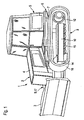
- the crawler 1 has according to Fig. 1 as a construction vehicle 2, a tool 3, for example in the form of a shield or the like, and further comprises a vehicle engine 4 and other components of an upper vehicle 5 and a lower vehicle 6.
- An essential part of the lower vehicle 6 is a trough-shaped vehicle frame 7, on both sides of each chassis 8 and 9, each with a chassis support 10, 11 for at least one drive wheel 12, 13, for guide wheels 14 and support wheels 15 for guiding caterpillars 16 and 17 is provided.
- the drive wheels 12, 13 are gears.
- the vehicle frame 7 comprises a right side wall 18 and a left side wall 19 and a rear wall 20 connecting these two side walls 18 and 19 at the rear and a bottom 21.
- Both landing gear supports 10, 11 are detachably connectable to the vehicle frame 7 with their respective components for changing the track width in the exemplary embodiments illustrated in the figures.
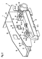
- attachment points 22 and 23 are in the in Fig. 2 illustrated embodiment formed by means of carrying means 24, 25 serving as support arms 24 'and 24 "or 25' and 25" on the one hand and of receiving and supporting means 26, 27 serving receiving parts 26 ', 26 "and 27', 27" on the other hand, which are each arranged in alignment with the chassis carriers 10, 11 and on the vehicle frame 7.
- each chassis support 10, 11 is U-shaped in cross-section and has between side panels a support plate 28' and 28" on.
- Each freely projecting support arm 24 'or 24 " is suitably welded to the chassis support 10, 11.
- the other or rear support arm 25 ', 25 may also be U-shaped in cross-section, but it is expediently L-shaped in cross-section.
- the receiving parts 26 ', 26 "and 27' and 27" are also U-shaped and / or L-shaped in cross section.
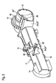
- the support arms 24 ', 24 "and 25', 25" and the receiving parts may each be hollow profiles, since at least the rear, located at the drive wheels 12, 13 support arms 25 ', 25 "preferably a passage opening 29 (FIGS. Fig. 3 ) for not shown lines for the power supply of drives 30 and 31, which are arranged on the chassis beams 10, 11.
- All support arms 24 ', 24 "and 25', 25” are either arranged laterally cantilevered from the chassis beams 10, 11 or at least project laterally. Telescopically, they can be in the receiving and supporting means 26, 27, arranged on the vehicle frame 7, also laterally projecting receiving parts 26 ', 26 "and 27', 27” either different far according to the desired position and use there with the help of holding - Solvents 32 and releasably fix in the form of holes, passages, tapped holes, threaded bolts or screws and possibly nuts.
- the freely cantilevered receiving parts 26 ', 26 “and 27' and 27" may be in one piece according to embodiment and to extend through the side walls 18, 19 in the interior 33 of the vehicle frame 7. In its interior 33, they may be connected to each other or consist of a one-piece profile part 34 or 35, each with free ends through openings 36 (FIG. Fig. 2 ) in the side walls 18, 19 to form the receiving parts.
- brackets 37, 38 may be provided to increase the bearing capacity of the receiving parts 26 'to 27 ".
- profile part 38 ( Fig. 2 Only its free ends which serve as receiving parts 27 ', 27 "are optionally L-shaped in cross-section, in addition to which the profile part 35 in the interior 33 of the vehicle frame 7 has a cross-section Through which the energy supply lines are led, which in the case of hydraulic drives 30, 31 produce the necessary energy supply to pumps, which in turn are driven by the vehicle engine 4 as the main engine.
- the immediately serving as a receiving and supporting means 27 part in cross-section is angular and thereby open downwards and toward the rear end 40 of the vehicle frame 7. It consists of a vertical leg 41 and a further leg 40 ", which extends from the upper end 40 '" of the first leg 40' horizontally in a direction to the rear end 40 of the vehicle frame 7.
- the track width variation can therefore be carried out very easily with sufficient play, even if the front receiving and supporting means 26 on the vehicle frame 7 receive the associated carrying means 24 on the chassis carriers 10, 11 in a form-fitting or almost positive manner. Nevertheless, the chassis support 10, 11 due to the L-shaped configuration of the receiving and supporting means 27 in a position to transfer the forces occurring in the direction of travel forward completely on the vehicle frame 7.
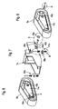
- Fig. 6 to 8 show a right and a left chassis 8a and 9a and a vehicle frame 7a of a modified embodiment, wherein like parts have basically the same reference numerals as the first embodiment and in addition the letter index a.
- a carrier arm 24a which is round in cross-section, or an axle 42a (pivot axis) is provided per vehicle side. They are in the assembled state in each case in a corresponding bore 43a in each of the two chassis beams 10a and 11a.
- axles 42a are fixed to the vehicle frame 7a by means of a cross-section e.g. Rectangular spacer 44a rigidly attached.
- the spacer sleeve 45a of two half-shells 46a and 47a can therefore be placed on the axle 42a or removed therefrom without the entire chassis 8a or 9a having to be completely removed from the axle 42a.
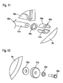
- the spacer bushing 45a on the axis 42a either on the frame side (large track width) or in the region of the outer end 47a of the axle 42a to achieve a narrow track width ( Fig. 11 ). This results in the position of the chassis 8a and 9a two different positions for the track width.
- a closed inner ring 48a is also provided.
- the front end 53a of the vehicle frame 7a on both sides provided respectively spring means 41a comprises according to Fig. 6 Chassis side console 54a, to which a support rod 55a is disposed at both ends thereof.
- the holding rod 55a is used for positionally accurate fixation of two coil springs 56a and 57a.
- the support rod 55a engages in the assembled state, the two springs 56a and 57a and further a support and guide bracket 58a, which has a guide sleeve 59a for the support rod 55a.
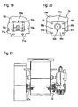
- the two mutually facing ends 64a and 65a of the two springs 56a and 57a are in the assembled state on a holding plate 66a of the carrying and guiding console 58a, in which the guide sleeve 59a is located ( Fig. 10 respectively. Fig. 21 ).
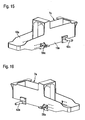
- the carrying guide consoles 58a are basically fastened or screwed on the outside of the vehicle frame 7a or on the frame side ( Fig. 7 or 13 and 14).
- the spacer 67a is according to embodiment in cross-section H-shaped and consists of integral formation of a centrally located block and two aligned therewith arranged plates with mounting holes.
- the spacers 45a are respectively close to the side walls 18a and 19a of the vehicle frame 7a, as shown in FIG Fig. 25 is illustrated, it is understood that the support and guide brackets 58a must be secured using spacers 67a on the outside on the side walls 18a and 19a of the vehicle frame 7a. The corresponding goes from the Fig. 21 and 22 out.
- the Fig. 13 to 20 also show various mounting options for the axes 42a and for the support and guide brackets 58 a respectively on the side walls 18a and 19a of the vehicle frame 7a.
- the carrying and guiding console 58a has a sufficient number of holes 70a for fastening screws on.
- Corresponding holes 71a which may be simple holes or slots, are located in the side walls 18a and 19a, respectively. Specifically, such holes 71a are provided in a larger number such that the support and guide brackets 58a can not only be fixed to a single, predetermined place on the vehicle frame 7a, but at several points at different distances from the axis 42a and at different height level.
- the two side walls 18a and 19a therefore have significantly more holes 71a and slots 71a than would be required for a single, positionally accurate attachment of the support and guide brackets 58a.
- the axis 42a is located at an intermediate piece 44a.
- This intermediate piece 44a may be square in cross-section or according to the in the Fig. 13 and 15 or 20 illustrated spacers 44a be deviating from the square shape rectangular.
- the respective axis 42a is located on the intermediate piece 44a in an eccentrically mounted position.
- the intermediate pieces 44 a have in accordance with Fig. 13 . 15 and 20 a plurality of holes 80a and corresponding holes in the Fig. 20 Under the intermediate piece 44a are located in the side walls 18a and 19a of the vehicle frame 7a, so that the intermediate pieces 44a with their axes 42a can be fastened with the help of likewise not shown screws on the side walls 18a and 19a of the vehicle frame 7a in an expedient manner.
- additional holes 81a ( Fig. 20 ) in the intermediate piece or pieces 44a. These additional holes 81a are in a case of attachment of the spacers 44a in a first position according to the Fig. 13 and 20 not required.
- the intermediate pieces 44a are fixed to the sidewalls 18a and 19a in a position rotated 180 degrees.
- the holes 81a are in place of the upper holes 80a according to Fig. 20 above (not shown).
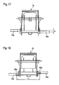
- the axis 42a is replaced by a lower position, as shown by a comparison of FIGS. 15 and 16 emerges or on the basis of FIGS. 17 and 18 can be seen.
- chassis beams 10a and 11a it is not only possible to change the distance of the chassis beams 10a and 11a to the vehicle frame 7 and 7a, but it may also be an arrangement of the chassis beams and 10 or 11 or 10a and 11a be achieved at different height level both in the area of the axes 42a and in the region of the spring means 41a.
- a caterpillar vehicle thus not only has the possibility of changing the track width (distance c according to FIG Fig. 18 ), but also the distance a ( Fig. 14 ) of the axles 42a of the carrying and guiding consoles 58a of the spring means 41a can be adjusted.
- the position or the height level of the axles 42a on the vehicle frame 7a is also in accordance with the distance b Fig. 17 variable. The same applies to the height level of the carrying and guiding consoles 58a.
- To track width change according to the distance c in Fig. 18 serve the spacers 45 a and the spacers 67 a according to the Fig. 21 to 23 ,
- the distances a and b are achieved by means of additionally provided holes either in the side walls 18a and 19a or in the intermediate pieces 44a.
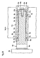
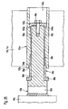
- the two Fig. 24 and 25 show in part the section serving as a support arm and as a pivot axis axis 42a, for example, on the intermediate piece 44a for attachment to the vehicle frame 7a (FIG. Fig. 13 ) is welded.
- the axis 42a has in the region of its attachment point serving as a stop axle piece 85a with a larger diameter than the rest of the axis 42a to its free end 86a.
- the axle piece 85a merges with the smaller diameter axle piece 88a.
- a sleeve 89a of the same diameter as the axle piece 88a abuts axially and engages with a ring-shaped projection 90a in a carrying sleeve 91a.
- a support sleeve 91a is disposed in each chassis support 10a and 11a and has a bore 43a, which also in the 6 and 8 is shown.
- the outer circumference of the support sleeve 91 a is cylindrical according to embodiment, as shown in the Fig. 24 and 25 is shown.
- each of the support sleeves 91a is offset several times.
- a first large diameter bore piece 92a is connected to a smaller diameter bore piece 93a and a central bore piece 94a, then to the shoulder 87a again a bore piece 95a having a diameter such as the bore piece 93a and finally a relatively short bore piece 96a with an inside diameter like the hole piece 92a.
- the annular projection 90a of the sleeve 89a is located at a small track width adjustment Fig. 24 , Further, in this case, there is an annular air gap 97a between the annular projection 90a and the inner contour of the short bore piece 96a.
- the two bore pieces 93a and 95a serve to receive short bearing sleeves 98a and 99a, each with a low material thickness.
- the spacer bushing 45a is located in the hole piece 92a. It sits on the free end 86a of the shaft 42a and has, according to the embodiment in one-piece design, an axially inner ring piece 100a with a larger outer diameter and a ring piece 101a with a slightly smaller outer diameter.
- the disk-shaped pressure piece 51a On the front side of the ring piece 101a is the disk-shaped pressure piece 51a (see also Fig. 12 ) with an annular end face 103a.
- the spacer bushing 45a may be in one piece or consists of two half-shells 46a, 47a (as already explained above). Fig. 11 ).
- the fastening screw 49a ( Fig. 24 ), whereupon the landing gear carrier 10a, 11a is withdrawn so far axially from the axis 42a until the spacer sleeve 45a can be removed.
- the spacer bushing 45a which preferably consists of two half-shells, is placed on the axle piece 88a of the shaft 42a close to the axle piece 85a serving as a stop. This is done so that the ring piece 101a abuts against the annular projection 90a of the sleeve 89a.
- the landing gear carrier 10a, 11a is again pushed axially onto the axle 42a until the carrying sleeve 91a receives the ring piece 100a with its short bore piece 96a as far as possible against an end face 104a ( Fig. 25 ). Then, the fastening screw 49a is tightened, whereupon the chassis support 10a or 11a is fixed with a larger track width corresponding to the axial length of the spacer sleeve 45a.
- the pressure plate 102a (see Fig. 25 ) the landing gear carrier 10, 11a on the axially immovably arranged in him support sleeve 91a, since it rests with its end face 103a on a shoulder 104a between the bore piece 92a and the bore piece 93a.
Landscapes
- Engineering & Computer Science (AREA)
- Chemical & Material Sciences (AREA)
- Combustion & Propulsion (AREA)
- Transportation (AREA)
- Mechanical Engineering (AREA)
- Body Structure For Vehicles (AREA)
- Agricultural Machines (AREA)
Claims (20)
- Véhicule chenillé avec écartement variable, en particulier un véhicule de la construction (1) avec au moins un outil (3) et/ou un véhicule agricole, ayant au moins un moteur de véhicule (4) et une superstructure de véhicule (5) comprenant d'autres composants et ayant une substructure de véhicule (6) comprenant un châssis de véhicule (7), des deux côtés duquel est prévu un train de roulement (8, 9) avec un support de train de roulement (10, 11) pour au moins une roue motrice (12, 13) à chaque fois, une roue de renvoi (14) et pour des roues de support (15) pour des trains à chenilles (16, 17), la distance des trains à chenilles (16, 17) du châssis de véhicule (7) étant variable et au moins un des deux supports de train de roulement (10, 11) étant attachable de manière détachable au châssis de véhicule (7) à des distances différentes à angles droits à la substructure de véhicule (6) à l'aide de moyens porteurs (24, 25) ainsi qu'à l'aide de moyens de logement et de support (26, 27) ainsi qu'à l'aide de moyens d'attachement et de détachement (28),
caractérisé en ce
que des deux côtés du véhicule, sont prévus un bras de support de section circulaire sous forme d'arbre (42a) ainsi qu'au moins une douille d'espacement (45a) détachable près d'un bout du châssis de véhicule (7a) et au moins un dispositif à ressorts (41 a) et une pièce d'écartement détachable (67a) près de l'autre bout du châssis de véhicule (76a), à chaque fois en combinaison avec des moyens d'attachement et de détachement, en tant que moyens porteurs (24a) et en tant que moyens de logement et de support (26a),
le dispositif à ressorts (41 a) comprenant au moins un ressort (56a, 57a) et, du côté du train de roulement, une console (54a) et, du côté du châssis, une console porteuse et de guidage (58a), et étant attachable à l'aide de celles-ci au châssis de véhicule (7a) et aux supports de train de roulement (10a, 11a) ou en utilisant additionnellement au moins une pièce d'écartement (67a). - Véhicule chenillé selon la revendication 1,
caractérisé en ce
que les moyens porteurs (24, 25), d'un côté, et les moyens de logement et de support (26, 27), de l'autre côté, sont ménagés au support de train de roulement (10, 11) et/ou au châssis de véhicule (7). - Véhicule chenillé selon la revendication 1,
caractérisé en ce
qu'un bras de support (24', 25') en porte-à-faux est prévu en tant que moyen porteur (24, 25). - Véhicule chenillé selon la revendication 3,
caractérisé en ce
qu'au moins une partie de la section du bras de support (24') est en forme d'U. - Véhicule chenillé selon la revendication 3,
caractérisé en ce
qu'au moins une partie de la section du bras de support (25') est en forme de L. - Véhicule chenillé selon la revendication 1,
caractérisé en ce
que chacun des moyens de logement et de support (26, 27) sont des pièces de logement (26', 26", 27', 27") avec une section en forme d'U et/ou en forme de L. - Véhicule chenillé selon la revendication 4,
caractérisé en ce
que les bras de support (24') ayant une section en forme d'U sont ménagés au châssis de véhicule (7) et/ou au support de train de roulement (10, 11) avec l'ouverture de leur section tournée vers le bas. - Véhicule chenillé selon la revendication 5,
caractérisé en ce
que les moyens de logement et de support (26, 27) sont ménagés au châssis de véhicule (7) et/ou au support de train de roulement (10, 11) avec l'ouverture de leur section tournée vers le bas. - Véhicule chenillé selon la revendication 2,
caractérisé en ce
que les moyens de logement et de support (26, 27) sont ménagés en porte-à-faux latéral au-delà de panneaux latéraux (18, 19) du châssis de véhicule (7). - Véhicule chenillé selon la revendication 9,
caractérisé en ce
que les pièces de logement (26', 26", 27', 27") se trouvant en porte-à-faux latéral au-delà du châssis de véhicule (7) en tant que moyens de logement et de support (26, 27) sont des pièces profilées (34, 35) qui s'étendent intégralement à travers l'intérieur (33) du châssis de véhicule (7). - Véhicule chenillé selon la revendication 10,
caractérisé en ce
qu'au moins une pièce profilée (35) comprend une ouverture (39) menant dans l'intérieur (33) du châssis de véhicule (7). - Véhicule chenillé selon la revendication 1,
caractérisé en ce
qu'un entraînement (30, 31) pour chaque train à chenille (16, 17) est ménagé directement au support de train de roulement (10, 11) respectif. - Véhicule chenillé selon la revendication 1,
caractérisé en ce
qu'au moins un moyen de logement et de support (27) ménagé au châssis de véhicule (7) a une section angulaire, une branche (40') des moyens de logement et de support (27) étant en position debout et l'autre branche (40") s'étendant, à partir du bout supérieur (40"') de la première branche (40'), en position horizontale vers le bout arrière (40) du châssis de véhicule (7). - Véhicule chenillé selon l'une quelconque des revendications 1 à 13,
caractérisé en ce
que la position emboîtée de la douille d'espacement (45a) sur l'arbre (42a) peut être commutée librement entre une position axialement intérieure et une position axialement extérieure. - Véhicule chenillé selon l'une quelconque des revendications 1 à 13,
caractérisé en ce
que la douille d'espacement (45a) est constituée de semi-monocoques (46a, 47a). - Véhicule chenillé selon l'une quelconque des revendications 1 à 15,
caractérisé en ce
que le support de train de roulement (10a, 11a) comprend indirectement ou directement un alésage (43a) pour recevoir un arbre (42a) servant de bras de support et en même temps en tant qu'axe de pivotement ainsi que de moyen d'attachement. - Véhicule chenillé selon l'une quelconque des revendications 1 à 16,
caractérisé en ce,
qu'en cas de l'écartement étroit, la douille d'espacement (45a) est ménagée au bout libre (86a) de l'arbre (42a) dans une position axialement extérieure. - Véhicule chenillé selon l'une quelconque des revendications 1 à 17,
caractérisé en ce
que la douille d'espacement (45a) est ménagée au moins partiellement à l'intérieur d'un alésage (43a) recevant l'arbre (42a), dit alésage (43a) se trouvant directement ou indirectement dans le support de train de roulement (10a, 11a). - Véhicule chenillé selon l'une quelconque des revendications 1 à 18,
caractérisé en ce,
qu'en cas de l'écartement large, la douille d'espacement (45a) est ménagée, du côté du châssis, sur l'arbre (42a) entre un épaulement annulaire (87a) servant d'arrêt d'arbre, et le support de train de roulement (10a, 11a). - Véhicule chenillé selon la revendication 19,
caractérisé en ce,
qu'en cas de l'écartement large, la douille d'espacement (45a) est ménagée, du côté du châssis, sur l'arbre (42a), ainsi que partiellement dans l'alésage (43a) recevant l'arbre (42a), se trouvant dans le support de train de roulement (10a, 11a).
Priority Applications (5)
| Application Number | Priority Date | Filing Date | Title |
|---|---|---|---|
| CA002464908A CA2464908A1 (fr) | 2003-04-14 | 2004-04-08 | Vehicule chenille a voie variable |
| PL367177A PL208746B1 (pl) | 2003-04-14 | 2004-04-13 | Pojazd gąsienicowy o zmiennym rozstawie kół |
| BR0401112-0A BRPI0401112A (pt) | 2003-04-14 | 2004-04-13 | Veìculo-lagarta com bitola alterável |
| RU2004111489/11A RU2310574C2 (ru) | 2003-04-14 | 2004-04-14 | Транспортное средство на гусеничном ходу с изменяемой колеей |
| US10/825,079 US7373999B2 (en) | 2003-04-14 | 2004-04-14 | Crawler-tracked vehicle with variable track width |
Applications Claiming Priority (2)
| Application Number | Priority Date | Filing Date | Title |
|---|---|---|---|
| DE10317309 | 2003-04-14 | ||
| DE2003117309 DE10317309A1 (de) | 2003-04-14 | 2003-04-14 | Raupenfahrzeug mit veränderbarer Spurbreite |
Publications (3)
| Publication Number | Publication Date |
|---|---|
| EP1468901A2 EP1468901A2 (fr) | 2004-10-20 |
| EP1468901A3 EP1468901A3 (fr) | 2005-03-23 |
| EP1468901B1 true EP1468901B1 (fr) | 2009-10-14 |
Family
ID=32892356
Family Applications (1)
| Application Number | Title | Priority Date | Filing Date |
|---|---|---|---|
| EP20040006506 Expired - Lifetime EP1468901B1 (fr) | 2003-04-14 | 2004-03-18 | Engin à chenille à voie variable |
Country Status (2)
| Country | Link |
|---|---|
| EP (1) | EP1468901B1 (fr) |
| DE (2) | DE10317309A1 (fr) |
Families Citing this family (4)
| Publication number | Priority date | Publication date | Assignee | Title |
|---|---|---|---|---|
| DE102011102110B4 (de) * | 2011-05-20 | 2023-05-17 | Liebherr-Werk Ehingen Gmbh | Unterwagen für Raupenkran, Raupenkran und Verfahren zum Auf- und Abbau eines Raupenkrans |
| AU2012337985B2 (en) * | 2011-11-14 | 2016-05-19 | Hitachi Construction Machinery Co., Ltd. | Truck frame for construction machinery |
| US11260921B2 (en) | 2018-10-19 | 2022-03-01 | Clark Equipment Company | Rigid track mount |
| DE202020101133U1 (de) * | 2020-03-02 | 2021-06-04 | Liebherr-Werk Nenzing Gmbh | Unterwagen für eine Arbeitsmaschine |
Family Cites Families (5)
| Publication number | Priority date | Publication date | Assignee | Title |
|---|---|---|---|---|
| US3998286A (en) * | 1975-11-19 | 1976-12-21 | Caterpillar Tractor Co. | Mechanically, laterally adjustable treads for crawler vehicles |
| JPS5621979A (en) * | 1979-07-27 | 1981-02-28 | Hitachi Constr Mach Co Ltd | Truck structure for construction vehicle |
| US5293948A (en) * | 1992-09-25 | 1994-03-15 | Caterpillar Inc. | Undercarriage assembly for a vehicle |
| WO1998040264A1 (fr) * | 1997-03-13 | 1998-09-17 | Caterpillar Inc. | Systeme de transmission pour machine de travaux entrainee par courroie |
| US6318484B2 (en) * | 1999-09-20 | 2001-11-20 | Case Corporation | Tracked suspension |
-
2003
- 2003-04-14 DE DE2003117309 patent/DE10317309A1/de not_active Withdrawn
-
2004
- 2004-03-18 EP EP20040006506 patent/EP1468901B1/fr not_active Expired - Lifetime
- 2004-03-18 DE DE200450010219 patent/DE502004010219D1/de not_active Expired - Lifetime
Also Published As
| Publication number | Publication date |
|---|---|
| DE502004010219D1 (de) | 2009-11-26 |
| EP1468901A2 (fr) | 2004-10-20 |
| EP1468901A3 (fr) | 2005-03-23 |
| DE10317309A1 (de) | 2004-10-28 |
Similar Documents
| Publication | Publication Date | Title |
|---|---|---|
| DE102018132378A1 (de) | Bodenbearbeitungsmaschine | |
| EP0335124A1 (fr) | Dispositif de montage automatique pour joindre par en dessous des sous-ensembles à une carrosserie d'automobile | |
| EP1053669B1 (fr) | Véhicule | |
| EP1650055B1 (fr) | Pont d'entraînement | |
| EP1522455A2 (fr) | Dispositif de protection de chargement dans les unités de transport | |
| EP0979748A2 (fr) | Monture de siège d'un siège de véhicule réglable | |
| DE102009040079A1 (de) | Gleitschalungsfertiger | |
| EP1468901B1 (fr) | Engin à chenille à voie variable | |
| EP0754829A1 (fr) | Dispositif pour le raccordement d'un élément pivotant, p.ex. d'un capot de véhicule à un corps, p.ex. à un châssis de véhicule | |
| EP3165076B1 (fr) | Châssis porté pour véhicule utilitaire | |
| DE2805635C2 (de) | Vorrichtung zum seitlichen Ausscheren von Kraftfahrzeugen | |
| DE60218731T2 (de) | Rollstuhl | |
| EP3170722B1 (fr) | Procédé et dispositif de montage d'un véhicule, en particulier un véhicule utilitaire | |
| EP0678443A1 (fr) | Train de roulement, notamment pour machines de travail mobiles et véhicules | |
| EP1974594B1 (fr) | Machine de traitement de sol | |
| EP0635198B1 (fr) | Moissonneuse-batteuse | |
| EP0783427B1 (fr) | Appareil mobile a roues et a pedales | |
| DE19739365C2 (de) | Vorrichtung zum Einspeichen eines Rades | |
| DE3914423C2 (de) | Zubehör für Anbaugeräte | |
| EP0804897A2 (fr) | Machine pour nettoyer les sols, en particulier machine pour aspirer et frotter | |
| DE3016959C2 (fr) | ||
| DE102021118688A1 (de) | Selbstfahrende bodenfräsmaschine, adapterset für eine bodenfräsmaschine sowie verfahren zum inkrementellen verschieben und/oder vergrössern des hubbereiches | |
| DE69210572T2 (de) | Schnellwechselbare Abschneidescherenvorrichtung für eine Maschine zum Formen von Glasgegenständen | |
| DE3019348A1 (de) | Anbaudrehpflug | |
| DE3153007C2 (fr) |
Legal Events
| Date | Code | Title | Description |
|---|---|---|---|
| PUAI | Public reference made under article 153(3) epc to a published international application that has entered the european phase |
Free format text: ORIGINAL CODE: 0009012 |
|
| AK | Designated contracting states |
Kind code of ref document: A2 Designated state(s): AT BE BG CH CY CZ DE DK EE ES FI FR GB GR HU IE IT LI LU MC NL PL PT RO SE SI SK TR |
|
| AX | Request for extension of the european patent |
Extension state: AL LT LV MK |
|
| PUAL | Search report despatched |
Free format text: ORIGINAL CODE: 0009013 |
|
| AK | Designated contracting states |
Kind code of ref document: A3 Designated state(s): AT BE BG CH CY CZ DE DK EE ES FI FR GB GR HU IE IT LI LU MC NL PL PT RO SE SI SK TR |
|
| AX | Request for extension of the european patent |
Extension state: AL LT LV MK |
|
| RIC1 | Information provided on ipc code assigned before grant |
Ipc: 7B 62D 49/06 B Ipc: 7B 62D 55/084 A |
|
| 17P | Request for examination filed |
Effective date: 20050923 |
|
| AKX | Designation fees paid |
Designated state(s): BE DE FR GB IT |
|
| 17Q | First examination report despatched |
Effective date: 20051110 |
|
| GRAP | Despatch of communication of intention to grant a patent |
Free format text: ORIGINAL CODE: EPIDOSNIGR1 |
|
| RIN1 | Information on inventor provided before grant (corrected) |
Inventor name: HARINGER, ALOIS JOHANN |
|
| GRAS | Grant fee paid |
Free format text: ORIGINAL CODE: EPIDOSNIGR3 |
|
| GRAA | (expected) grant |
Free format text: ORIGINAL CODE: 0009210 |
|
| AK | Designated contracting states |
Kind code of ref document: B1 Designated state(s): BE DE FR GB IT |
|
| REG | Reference to a national code |
Ref country code: GB Ref legal event code: FG4D Free format text: NOT ENGLISH |
|
| REF | Corresponds to: |
Ref document number: 502004010219 Country of ref document: DE Date of ref document: 20091126 Kind code of ref document: P |
|
| PLBE | No opposition filed within time limit |
Free format text: ORIGINAL CODE: 0009261 |
|
| STAA | Information on the status of an ep patent application or granted ep patent |
Free format text: STATUS: NO OPPOSITION FILED WITHIN TIME LIMIT |
|
| 26N | No opposition filed |
Effective date: 20100715 |
|
| PGFP | Annual fee paid to national office [announced via postgrant information from national office to epo] |
Ref country code: FR Payment date: 20110401 Year of fee payment: 8 |
|
| PGFP | Annual fee paid to national office [announced via postgrant information from national office to epo] |
Ref country code: DE Payment date: 20110331 Year of fee payment: 8 Ref country code: GB Payment date: 20110324 Year of fee payment: 8 Ref country code: BE Payment date: 20110328 Year of fee payment: 8 |
|
| PGFP | Annual fee paid to national office [announced via postgrant information from national office to epo] |
Ref country code: IT Payment date: 20110331 Year of fee payment: 8 |
|
| BERE | Be: lapsed |
Owner name: MACMOTER S.P.A. Effective date: 20120331 |
|
| GBPC | Gb: european patent ceased through non-payment of renewal fee |
Effective date: 20120318 |
|
| REG | Reference to a national code |
Ref country code: FR Ref legal event code: ST Effective date: 20121130 |
|
| REG | Reference to a national code |
Ref country code: DE Ref legal event code: R119 Ref document number: 502004010219 Country of ref document: DE Effective date: 20121002 |
|
| PG25 | Lapsed in a contracting state [announced via postgrant information from national office to epo] |
Ref country code: FR Free format text: LAPSE BECAUSE OF NON-PAYMENT OF DUE FEES Effective date: 20120402 Ref country code: GB Free format text: LAPSE BECAUSE OF NON-PAYMENT OF DUE FEES Effective date: 20120318 Ref country code: BE Free format text: LAPSE BECAUSE OF NON-PAYMENT OF DUE FEES Effective date: 20120331 |
|
| PG25 | Lapsed in a contracting state [announced via postgrant information from national office to epo] |
Ref country code: IT Free format text: LAPSE BECAUSE OF NON-PAYMENT OF DUE FEES Effective date: 20120318 |
|
| PG25 | Lapsed in a contracting state [announced via postgrant information from national office to epo] |
Ref country code: DE Free format text: LAPSE BECAUSE OF NON-PAYMENT OF DUE FEES Effective date: 20121002 |