EP1469770B1 - System zum nachweis von ventrikelkollaps - Google Patents
System zum nachweis von ventrikelkollaps Download PDFInfo
- Publication number
- EP1469770B1 EP1469770B1 EP03701265A EP03701265A EP1469770B1 EP 1469770 B1 EP1469770 B1 EP 1469770B1 EP 03701265 A EP03701265 A EP 03701265A EP 03701265 A EP03701265 A EP 03701265A EP 1469770 B1 EP1469770 B1 EP 1469770B1
- Authority
- EP
- European Patent Office
- Prior art keywords
- blood pump
- array
- fourier transform
- spectral
- flow
- Prior art date
- Legal status (The legal status is an assumption and is not a legal conclusion. Google has not performed a legal analysis and makes no representation as to the accuracy of the status listed.)
- Expired - Lifetime
Links
Images




Classifications
-
- A—HUMAN NECESSITIES
- A61—MEDICAL OR VETERINARY SCIENCE; HYGIENE
- A61M—DEVICES FOR INTRODUCING MEDIA INTO, OR ONTO, THE BODY; DEVICES FOR TRANSDUCING BODY MEDIA OR FOR TAKING MEDIA FROM THE BODY; DEVICES FOR PRODUCING OR ENDING SLEEP OR STUPOR
- A61M60/00—Blood pumps; Devices for mechanical circulatory actuation; Balloon pumps for circulatory assistance
- A61M60/40—Details relating to driving
- A61M60/403—Details relating to driving for non-positive displacement blood pumps
- A61M60/422—Details relating to driving for non-positive displacement blood pumps the force acting on the blood contacting member being electromagnetic, e.g. using canned motor pumps
-
- A—HUMAN NECESSITIES
- A61—MEDICAL OR VETERINARY SCIENCE; HYGIENE
- A61M—DEVICES FOR INTRODUCING MEDIA INTO, OR ONTO, THE BODY; DEVICES FOR TRANSDUCING BODY MEDIA OR FOR TAKING MEDIA FROM THE BODY; DEVICES FOR PRODUCING OR ENDING SLEEP OR STUPOR
- A61M60/00—Blood pumps; Devices for mechanical circulatory actuation; Balloon pumps for circulatory assistance
- A61M60/10—Location thereof with respect to the patient's body
- A61M60/122—Implantable pumps or pumping devices, i.e. the blood being pumped inside the patient's body
- A61M60/165—Implantable pumps or pumping devices, i.e. the blood being pumped inside the patient's body implantable in, on, or around the heart
- A61M60/178—Implantable pumps or pumping devices, i.e. the blood being pumped inside the patient's body implantable in, on, or around the heart drawing blood from a ventricle and returning the blood to the arterial system via a cannula external to the ventricle, e.g. left or right ventricular assist devices
-
- A—HUMAN NECESSITIES
- A61—MEDICAL OR VETERINARY SCIENCE; HYGIENE
- A61M—DEVICES FOR INTRODUCING MEDIA INTO, OR ONTO, THE BODY; DEVICES FOR TRANSDUCING BODY MEDIA OR FOR TAKING MEDIA FROM THE BODY; DEVICES FOR PRODUCING OR ENDING SLEEP OR STUPOR
- A61M60/00—Blood pumps; Devices for mechanical circulatory actuation; Balloon pumps for circulatory assistance
- A61M60/20—Type thereof
- A61M60/205—Non-positive displacement blood pumps
- A61M60/216—Non-positive displacement blood pumps including a rotating member acting on the blood, e.g. impeller
- A61M60/237—Non-positive displacement blood pumps including a rotating member acting on the blood, e.g. impeller the blood flow through the rotating member having mainly axial components, e.g. axial flow pumps
-
- A—HUMAN NECESSITIES
- A61—MEDICAL OR VETERINARY SCIENCE; HYGIENE
- A61M—DEVICES FOR INTRODUCING MEDIA INTO, OR ONTO, THE BODY; DEVICES FOR TRANSDUCING BODY MEDIA OR FOR TAKING MEDIA FROM THE BODY; DEVICES FOR PRODUCING OR ENDING SLEEP OR STUPOR
- A61M60/00—Blood pumps; Devices for mechanical circulatory actuation; Balloon pumps for circulatory assistance
- A61M60/50—Details relating to control
- A61M60/508—Electronic control means, e.g. for feedback regulation
- A61M60/515—Regulation using real-time patient data
- A61M60/523—Regulation using real-time patient data using blood flow data, e.g. from blood flow transducers
-
- A—HUMAN NECESSITIES
- A61—MEDICAL OR VETERINARY SCIENCE; HYGIENE
- A61M—DEVICES FOR INTRODUCING MEDIA INTO, OR ONTO, THE BODY; DEVICES FOR TRANSDUCING BODY MEDIA OR FOR TAKING MEDIA FROM THE BODY; DEVICES FOR PRODUCING OR ENDING SLEEP OR STUPOR
- A61M60/00—Blood pumps; Devices for mechanical circulatory actuation; Balloon pumps for circulatory assistance
- A61M60/50—Details relating to control
- A61M60/508—Electronic control means, e.g. for feedback regulation
- A61M60/538—Regulation using real-time blood pump operational parameter data, e.g. motor current
-
- A—HUMAN NECESSITIES
- A61—MEDICAL OR VETERINARY SCIENCE; HYGIENE
- A61M—DEVICES FOR INTRODUCING MEDIA INTO, OR ONTO, THE BODY; DEVICES FOR TRANSDUCING BODY MEDIA OR FOR TAKING MEDIA FROM THE BODY; DEVICES FOR PRODUCING OR ENDING SLEEP OR STUPOR
- A61M60/00—Blood pumps; Devices for mechanical circulatory actuation; Balloon pumps for circulatory assistance
- A61M60/50—Details relating to control
- A61M60/508—Electronic control means, e.g. for feedback regulation
- A61M60/538—Regulation using real-time blood pump operational parameter data, e.g. motor current
- A61M60/546—Regulation using real-time blood pump operational parameter data, e.g. motor current of blood flow, e.g. by adapting rotor speed
-
- A—HUMAN NECESSITIES
- A61—MEDICAL OR VETERINARY SCIENCE; HYGIENE
- A61M—DEVICES FOR INTRODUCING MEDIA INTO, OR ONTO, THE BODY; DEVICES FOR TRANSDUCING BODY MEDIA OR FOR TAKING MEDIA FROM THE BODY; DEVICES FOR PRODUCING OR ENDING SLEEP OR STUPOR
- A61M2205/00—General characteristics of the apparatus
- A61M2205/33—Controlling, regulating or measuring
- A61M2205/3331—Pressure; Flow
-
- A—HUMAN NECESSITIES
- A61—MEDICAL OR VETERINARY SCIENCE; HYGIENE
- A61M—DEVICES FOR INTRODUCING MEDIA INTO, OR ONTO, THE BODY; DEVICES FOR TRANSDUCING BODY MEDIA OR FOR TAKING MEDIA FROM THE BODY; DEVICES FOR PRODUCING OR ENDING SLEEP OR STUPOR
- A61M2205/00—General characteristics of the apparatus
- A61M2205/33—Controlling, regulating or measuring
- A61M2205/3331—Pressure; Flow
- A61M2205/3334—Measuring or controlling the flow rate
-
- A—HUMAN NECESSITIES
- A61—MEDICAL OR VETERINARY SCIENCE; HYGIENE
- A61M—DEVICES FOR INTRODUCING MEDIA INTO, OR ONTO, THE BODY; DEVICES FOR TRANSDUCING BODY MEDIA OR FOR TAKING MEDIA FROM THE BODY; DEVICES FOR PRODUCING OR ENDING SLEEP OR STUPOR
- A61M2205/00—General characteristics of the apparatus
- A61M2205/33—Controlling, regulating or measuring
- A61M2205/3365—Rotational speed
-
- A—HUMAN NECESSITIES
- A61—MEDICAL OR VETERINARY SCIENCE; HYGIENE
- A61M—DEVICES FOR INTRODUCING MEDIA INTO, OR ONTO, THE BODY; DEVICES FOR TRANSDUCING BODY MEDIA OR FOR TAKING MEDIA FROM THE BODY; DEVICES FOR PRODUCING OR ENDING SLEEP OR STUPOR
- A61M60/00—Blood pumps; Devices for mechanical circulatory actuation; Balloon pumps for circulatory assistance
- A61M60/10—Location thereof with respect to the patient's body
- A61M60/122—Implantable pumps or pumping devices, i.e. the blood being pumped inside the patient's body
- A61M60/126—Implantable pumps or pumping devices, i.e. the blood being pumped inside the patient's body implantable via, into, inside, in line, branching on, or around a blood vessel
- A61M60/148—Implantable pumps or pumping devices, i.e. the blood being pumped inside the patient's body implantable via, into, inside, in line, branching on, or around a blood vessel in line with a blood vessel using resection or like techniques, e.g. permanent endovascular heart assist devices
Definitions
- the invention relates generally to implanted or implantable blood pump systems, and more specifically, to a system for detecting the onset and/or presence of ventricular collapse associated with such pumps.
- implantable blood pump systems are employed in either of two circumstances. First an implantable blood pump may completely replace a human heart that is not functioning properly, or second, an implantable blood pump may boost blood circulation in patients whose heart is still functioning although pumping at an inadequate rate.
- U.S. Patent No. 6,183,412 which is commonly assigned, discloses a ventricle assist device (VAD) commercially referred to as the "DeBakey VAD ® ".
- VAD ventricle assist device
- the VAD is a miniaturized continuous axial-flow pump designed to provide additional blood flow to patients who suffer from heart disease.
- the device is attached between the apex of the left ventricle and the aorta. Proper blood flow through the device depends on an adequately filled ventricle and a positive differential pressure between the inlet and the outlet of the VAD pump.
- This device Since this device produces flow continually and actively fills, it has the potential to create low pressure at the inflow in order to produce flow. "Excess Suction” occurs when the pressure in the inflow cannula decreases significantly - the pump begins to "suck" the ventricle closed, which would greatly reduce the pumping capability of the native heart and VAD. Decreasing the VAD's speed during an excess suction condition would allow the ventricle to refill, and normal blood flow to resume. Additionally, the detection of ventricular collapse and the ability to automatically adjust the pump's speed may aid in maintaining correct blood flow to the patient.
- Excess suction may be caused by occlusion of the tip of the inflow cannula or by completely emptying the ventricle (ventricular collapse).
- sustained excess suction typically triggers a diagnostic alarm on the pump controller.
- Information in addition to a simple binary indicator is desirable as it would allow a physician or technician to make a more precise diagnosis.
- US Patent No. 6,066,086 describes an automatic speed control system for continually adjusting the speed of an implanted cardiac assist blood pump to an optimum level for the varying physiological needs of the patient. It does this by periodically and iteratively incrementing the speed setpoint of the pump. When the system detects the imminence of a ventricular collapse at diastole, it decrements the speed setpoint by a predetermined safety margin. An alarm condition is also provided if the setpoint decrease results in an insufficient blood flow rate through the pump. The flow rate and imminence of ventricular collapse are computed in real time as functions of only the pump's motor current and speed setpoint.
- EP-1046403-A1 describes a blood circulation assisting device using a continuous flow blood pump for blood feeding assistance to remove blood through a blood removing pipe and drive out blood at a predetermined flow rate through a blood feeding pipe.
- the blood circulation assisting device includes a current measuring unit for measuring current flowing through a motor driving the pump in order to use the current as data corresponding to a blood flow rate through the continuous flow blood pump and an amplitude detection unit for detecting, from an output of the current measuring unit, the amplitude of fluctuation of current flowing through the motor in order to use the amplitude as data corresponding to a flow rate amplitude due to flow rate fluctuation.
- the amplitude of this fluctuation is divided by an average current value and output as an amplitude index.
- WO01/72352 describes a left ventricular assist device (LVAD) having a rotodynamic blood pump that is powered by a brushless DC motor, wherein a power supply supplies power to the motor.
- LVAD left ventricular assist device
- Three feedback channels, one for each of voltage, current and motor speed lead to a microcontroller or microprocessor.
- the three feedback waveforms are analyzed, and from these waveforms, motor input power, patient heart rate, current pump flow rate, and systemic pressure are determined.
- the microprocessor then calculates a desired flow rate proportional to the patient heart rate.
- the microprocessor communicates a new power output to a commutation circuit, which regulates power to the motor.
- the pump also includes safety checks that are prioritized over desired pump flow. These include prevention of ventricular suction, low pulsatility, minimum and maximum pump speed, minimum speed-relative pump flow, minimum absolute pump flow, minimum and maximum motor input power.
- the present invention addresses shortcomings associated with the prior art.
- an implantable pump system is provided as defined in claim 1.
- FIG. 1 illustrates a ventricle assist device (VAD) system 10 such as disclosed in U.S. Patent No. 6,183,412 , which is commonly assigned and incorporated herein by reference in its entirety.
- the VAD system 10 includes components designed for implantation within a human body and components external to the body.
- Implantable components include a rotary pump 12 and a flow sensor 14.
- the external components include a portable controller module 16, a clinical data acquisition system (CDAS) 18, and a patient home support system (PHSS) 20.
- CDAS clinical data acquisition system
- PHSS patient home support system
- the implanted components are connected to the controller module 16 via a percutaneous cable 22.
- the VAD System 10 may incorporate an implantable continuous-flow blood pump, such as the various embodiments of axial flow pumps disclosed in U.S. Patent No. 5,527,159 or in U.S. Patent No. 5,947,892 , both of which are incorporated herein by reference in their entirety.
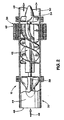
- An example of a blood pump suitable for use in an embodiment of the invention is illustrated in FIG. 2 .
- the exemplary pump 12 includes a pump housing 32, a diffuser 34, a flow straightener 36, and a brushless DC motor 38, which includes a stator 40 and a rotor 42.
- the housing 32 includes a flow tube 44 having a blood flow path 46 therethrough, a blood inlet 48, and a blood outlet 50.
- the stator 40 is attached to the pump housing 32, is preferably located outside the flow tube 44, and has a stator field winding 52 for producing a stator magnetic field.
- the stator 40 includes three stator windings and may be three phase "Y" or "Delta” wound.
- the rotor 42 is located within the flow tube 44 for rotation in response to the stator magnetic field, and includes an inducer 58 and an impeller 60. Excitation current is applied to the stator windings 52 to generate a rotating magnetic field.
- a plurality of magnets 62 are coupled to the rotor 42. The magnets 62, and thus the rotor 42, follow the rotating magnetic field to produce rotary motion.
- FIG. 3 conceptually illustrates aspects of the pump system 10. More specifically, portions of the controller module 16 and the pump 12 are shown.
- the controller module 16 includes a processor, such as a microcontroller 80, which in one embodiment of the invention is a model PIC 16C77 microcontroller manufactured by Microchip Technology.
- the microcontroller 80 includes a multiple channel analog to digital (A/D) converter, which receives indications of motor parameters from the motor controller 84.
- A/D analog to digital
- the controller module 16 may monitor parameters such as instantaneous motor current, motor voltage, and motor speed.
- the invention shown in FIG. 3 includes an integral flow meter 124. At least one flow sensor 14 is implanted down stream of the pump 12. Alternately, a flow sensor 14 may be integrated with the pump 12. The flow meter 124 is coupled between the implanted flow sensor 14 and the microcontroller 80. The flow meter 124 receives data from the flow sensor 14 and outputs flow rate data to the microcontroller 80, allowing the system to monitor instantaneous flow rate.
- flow rate is available for analysis, in addition to pump parameters such as motor speed and current (power). Further, since the flow meter 124 is an integral component of the controller module 16, flow rate may be displayed on the controller module display and flow rate data may be saved in the controller module memory.
- the motor controller 84 comprises a MicroLinear ML4425 Motor Controller from Fairchild Semiconductor.
- the operation of the brushless DC motor 38 of the present invention requires that current be applied in a proper sequence to the stator windings 52 to create the rotating field. Two stator windings 52 have current applied to them at any one time, and by sequencing the current on and off to the respective stator windings 52, the rotating magnetic field is produced.
- the motor controller 84 senses back electromotive force (EMF) voltage from the motor windings 52 to determine the proper commutation phase sequence using phase lock loop (PLL) techniques.
- EMF back electromotive force
- a conductor such as a stator winding 52
- a voltage is induced.
- the voltage will increase with rotor speed 42. It is possible to sense this voltage in one of the three stator windings 52 because only two of the motor's windings 52 are activated at any one time, to determine the rotor 42 position.
- An alternative method of detecting the rotor 42 position relative to the stator 40 for providing the proper stator winding 52 excitation current sequence is to use a position sensor, such as a Hall effect sensor.
- a position sensor such as a Hall effect sensor.
- adding additional components, such as Hall effect sensors requires additional space, which is limited in any implanted device application.
- using a position detection device adds sources of system failures.
- the motor controller 84 operates to maintain the pump 12 at an essentially constant speed regardless of the differential pressure across the pump or the flow through the pump. As noted above, the motor controller 84 uses a PLL to control the speed of the pump motor 38 (commutation control). An additional analog closed-loop control circuit controls the onboard pulse width modulator (PWM) to maintain a desired speed setting. Both control-loops work in unison to maintain proper speed control.
- PWM pulse width modulator
- the motor controller 84 forms a PLL with a voltage-controlled oscillator (VCO), back-EMF sampling error amplifier, loop-filter, sequencer, and output driver.
- VCO voltage-controlled oscillator
- the motor controller 84 samples the instantaneous motor phase that is not energized to determine whether to increase or decrease the commutator (VCO) frequency.
- the VCO generates an output frequency (commutation rate) proportional to input voltage.
- a late commutation causes the error amplifier to charge the loop filter, increasing the VCO input while early commutation causes the error amplifier to discharge the loop filter, decreasing the VCO input.
- the PWM loop operating at approximately 25 kHz in exemplary embodiments, effectively maintains the desired speed setting once the PLL has reached steady-state (the desired target speed). Constant speed control of the three-phase pump motor, under varying or pulsatile load conditions, is achieved by varying the amount of current delivered to the stator windings proportionally to the motor's load.
- the commutation and PWM loops have, because of their associated filter networks, individual frequency and time domain responses associated with them.
- the frequency range over which the loop system will follow changes in the input frequency is called the lock-in range.
- the frequency range in which the loop acquires phase-lock is the capture range.
- the dynamic characteristics of the phase-locked loop, and thus the way the pump motor responds to changes in load, are controlled primarily by the loop filter.
- the filter network included in the PLL serves two major functions. First, it removes any noise and high-frequency components from the error amplifer's output providing an average (dc) voltage to be fed to the VCO's input, and it is the primary element that determines the dynamic performance of the loop including capture (pull-in) range, lock-in range, bandwidth, and transient response.
- the filter limits the speed of the loop to track changes in the input frequency (motor speed).
- the loop filter provides a "fly-wheel” effect, ensuring a rapid recapture of the signal if the system is thrown out of lock by a noise transient.
- Variations in differential pressure across the pump 12 will impart instantaneous changes in the speed of the pump motor 38.
- the motor controller 84 will sense this change in speed through its back-EMF sampler and attempt to speed up or slow down the pump motor 38, such that the preset speed is maintained.
- This instantaneous load change and corresponding correction performed by the motor controller will result in a corresponding variation in the pump's current waveform, speed waveform, and flow waveform.
- An instantaneous increase in the pump's load will cause an instantaneous decrease in pump speed and thus an instantaneous increase in pump current and decrease in flow rate.
- an instantaneous decrease in the pump's load will cause an instantaneous increase in pump speed and thus an instantaneous decrease in pump current and increase in flow rate.
- the pump's current (and therefore power), speed, and flow waveforms correlate well with changes in the pump's load.
- These waveforms may be used to calculate the patient's heart rate, instantaneous and mean blood flow rate, regurgitant flow, instantaneous and mean power consumption, the pump's efficiency, etc.
- These waveforms also indicate when the pump's speed is set too high and the ventricle begins to collapse. This condition exists when the flow and/or current waveforms are highly-asymmetric and/or their peaks appear to contain multiple ripples or are flattened (clipped). Additionally, waveforms with short negative rise-times (attack) followed by slower positive exponential fall-times (decay) indicate suction.
- the aforementioned signals, current, speed, and flow are time-continuous band-limited signals.
- the current signal is a composite signal containing the motor controller's PWM frequency, the patients heart rate (assuming the heart is beating), and other frequencies relating to certain physiologic responses within the patient's cardiovascular system (e.g. valve openings and closures, changes in systemic resistance, etc.).
- the pulse-width modulation frequency typically is approximately 25 kHz and the patient's heart rate is approximately 0.7 Hz to 4.0 Hz.
- the power signal is the product of the pump motor current and pump motor voltage (a constant scalar) and is therefore a composite signal which, like the current, contains the motor controller's pulse-width modulation (PWM) frequency, the patient's heart rate (assuming there is a heart rate), and other frequencies relating to certain physiologic responses within the patient's cardiovascular system (e.g. valve openings and closures, changes in systemic resistance, etc.).
- PWM pulse-width modulation
- the pulse-width modulation frequency is approximately 25 kHz and the patient's heart rate is approximately 0.7 Hz to 4.0 Hz.
- the speed signal typically contains the heart rate of the patient (assuming the heart is beating) as the dominant frequency along with other frequencies related to certain physiologic responses within the patient's cardiovascular system (e.g. valve openings and closures, changes in systemic pressure, etc.).
- the angular momentum of the rotor impeller and viscosity of the blood dampen abrupt changes in speed and thus the bandwidth of this signal is typically under 30 Hz.
- the flow signal typically contains the heart rate of the patient (assuming the heart is beating) as the dominant frequency along with other frequencies related to certain physiologic responses within the patient's cardiovascular system (e.g. valve openings and closures, changes in systemic pressure, etc.).
- Time domain mechanisms include correlation techniques as well as linear and non-linear signal processing.
- Frequency domain mechanisms include various real-time spectral analysis methods using Fourier Transforms such as the Fast Fourier Transform (“FFT”) and the Discrete Fourier Transform (“DFT”), as well as other linear and non-linear signal processing techniques.
- FFT Fast Fourier Transform
- DFT Discrete Fourier Transform
- a physiologically appropriate flow(t) waveform is assumed to be quasi-sinusoidal at a single frequency proportional to the patient's native heart rate (i.e. fundamental frequency).
- the corresponding physiologically appropriate flow(f) waveform will be a single narrow spectral peak at the same single frequency proportional to the patient's native heart rate.
- the flow(f) waveform will contain additional spectral peaks corresponding to flow contributions at varying frequencies.
- the Fourier Series may be used to compute the fundamental and harmonic components from time domain signals that are continuous and periodic .
- Many in vivo waveforms that may denote suction, however, are not periodic, and further, the frequency components of such waveforms may not be harmonically related to the fundamental frequency.
- many frequency components, both harmonically related and not, about the fundamental are analyzed to precisely detect suction.
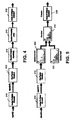
- FIG. 4 illustrates ventricular collapse methods based on a spectral analysis as described herein.
- the embodiments shown in block diagram form in FIG. 4 operate on the principle that the onset of ventricular collapse is imminent when the flow and/or current waveforms are asymmetric and/or their peaks appear to contain multiple ripples or are flattened (clipped). Variations in the flow, speed, current, and power waveforms in the time-domain will result in corresponding variation in their frequency-domain representations.
- one or more time-continuous band-limited signals are received and converted to a digital signal.
- the flow signal provided via the flow sensor 14 and flow meter 124 is specifically analyzed for suction detection, though one or more of the current, power, speed, etc. signals available may be used.
- the spectral content of the sampled signals are computed in block 212.
- a Fourier Transform such as the Discrete Fourier Transform (“DFT”), and/or Fast Fourier Transform (“FFT”) may be used to obtain the frequency-domain responses for the signals converted in block 210.
- DFT Discrete Fourier Transform
- FFT Fast Fourier Transform
- the FFT is more efficient computationally than is the DFT and is more easily realized in hardware and/or software. Continuous conversion of the time-continuous signals from the time-domain to the frequency-domain provides real time spectral content information about these signals.
- the array generated in block 212 is processed by spectral analysis equations in block 214 to generate a suction probability index in block 216, which may be expressed as a percentage.
- the suction probability index provides an indication of the imminence of ventricle collapse in block 218.
- Known methods to detect the onset or presence of ventricular collapse use a binary "suction detect" indicator when onset is discovered. No "suction indices" are used. The use of "suction indices" leads to a more precise diagnosis and gives the physician access to more information than a simple binary answer.
- Exemplary spectral analysis equations 214 used as described herein for processing the data to generate the suction probability index 216 include analyses based on harmonic distortion, total spectral distortion (harmonic distortion and noise), sub-fundamental distortion (distortion below the fundamental frequency), super-fundamental distortion (distortion above the fundamental frequency), the ratio of the super-fundamental distortion to the sub-fundamental distortion, super-physiologic distortion (distortion at frequencies above the assumed maximum physiologic fundamental frequency - typically 4Hz or 240 BPM), and the spectral dispersion or "width" of the resulting flow(f) waveform.
- harmonic distortion harmonic distortion and noise
- sub-fundamental distortion disortion below the fundamental frequency
- super-fundamental distortion disortion above the fundamental frequency
- super-physiologic distortion dispersion or "width" of the resulting flow(f) waveform.
- the spectral distortion factor measures the ratio of all energy contributed by all frequencies about the fundamental frequency with respect to the fundamental frequency. A higher distortion ratio indicates a higher probability of suction.
- the harmonic distortion factor measures the ratio of energy contributed by all harmonics about the fundamental frequency with respect to the fundamental frequency.
- the sub-fundamental distortion factor measures the additive frequency contributions below the fundamental frequency with respect to the fundamental frequency.
- the super-fundamental distortion factor measures the additive frequency contributions above the fundamental frequency with respect to the fundamental frequency.
- the super/sub fundamental distortion factor measures the ratio of additive frequency contributions above the fundamental frequency to the additive frequency contributions below the fundamental frequency.
- the spread of the waveform is measured.
- a physiologically appropriate waveform in the time domain is quasi-sinusoidal at a single frequency proportional to the patient's native heart rate, and hence, the corresponding physiologically appropriate waveform in the frequency domain will be a singly narrow spectral peak at the same single frequency proportional to the patient's native heart rate. Deviations from this quasi-sinusoidal case may indicate suction as well as other defects.
- the flow(f) waveform will contain additional flow contributions at varying frequencies and will thus begin to "widen".
- the probability that suction is imminent or present increases proportionally to the width of flow(f).
- the measure of the width of ffow(f) about the fundamental frequency is the square-root of the mean-squared variation about the fundamental frequency.
- the spectral dispersion factor measures the "width" of the flow(f), current(f), speed(f), and/or power(f) signals:
- f 1 is the fundamental frequency, the maximum (amplitude) spectral peak in the FFT resultant array
- dF represents the frequency resolution/interval of the resulting FFT operation in Hertz
- n indicates the spectral component's index/position in the resulting array
- FIGs. 5 and 6 Some alternatives to applying the spectral content of the measured signal to spectral analysis equations are shown in FIGs. 5 and 6 , where the real time spectral content measured signal is compared to a predetermined spectral mask.
- the spectral content 220 generated by the FFT 212 is compared to a predetermined spectral mask 222 in a combiner block 224.
- the presence of suction is determined based on the comparison.
- the signals whose spectral components fall within the mask indicate suction and, conversely, signals whose spectral components fall outside the mask indicate normal flow.
- the time domain responses are converted to frequency domain through the application of a synchronous switched-capacitor filter 230.
- the frequency response of the filter 230 is controlled by a clock source one hundred times the desired pass-band frequency.
- a phase-locked loop 232 generates this clocking signal to the filter 230 by receiving the output from a zero crossing detector 234 and multiplying the incoming fundamental frequency by an integer multiplier 236, the value of which is selected by a digital input element such as a microcontroller. Incrementing the integer multiplier will cause the synchronous filter to "track" the incoming signal and output the spectral amplitude of the fundamental frequency, first harmonic, second harmonic, etc. The sum of the individual spectral amplitudes results in a frequency-domain representation of the time-domain signals.
- a comparison may then be made between the real-time spectral content 220 of these signals and the predetermined spectral mask 222.
- Signals whose spectral components fall within the mask indicate suction and, conversely, signals whose spectral components fall outside the mask indicate normal flow.
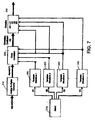
- FIG. 7 illustrates a method that cross-correlates the incoming time-sampled signal (for example, the flow or current signal) with predetermined time-domain waveforms 250 exemplifying the imminence of ventricular collapse.
- the waveforms 250 are selected in block 252 sequentially or based on the probability of occurrence in that particular patient derived experientially through clinical evaluation.
- a correlation coefficient is generated in block 254, where
- 1 signifies a perfect "match" and
- 0 indicates no correlation at all.
- the correlation coefficient is compared to predetermined thresholds in block 256 to derive a suction probability index. If the calculated correlation coefficient exceeds a predetermined value, ventricular collapse is imminent. Conversely, if the calculated correlation coefficient is below the predetermined value, suction is not present.
- the incoming time-sampled signal may be cross-correlated with time-domain representations of sine waves at integer multiples of the incoming fundamental frequency.
- the sum of the individual spectral amplitudes results in a frequency-domain representation of the time-domain signals.
- a comparison is then made between the real-time spectral content of these signals and a predetermined spectral mask as in the embodiments shown in FIGs. 5 and 6 . Signals whose spectral components fall within the mask indicate suction and, conversely, signals whose spectral components fall outside the mask indicate normal flow.
- Still further analysis methods continuously time-sample signals representing system parameters including flow, and optionally speed, current, or power, and calculate the slope between a series of data points. By comparing the calculated slope to a predetermined value, ventricular collapse may be detected. This may also be applied to the first or second derivatives of the flow, current, speed, and/or power signals.
- the derivative of the time- sampled signal, such as flow, with respect to time is calculated in block 260, which yields blood acceleration. Therefore, a large negative dflow(t)/dt indicates the presence of ventricular collapse.
- the calculated derivative is provided as one input to a comparitor 262.
- An adjustable suction detect threshold value 264 is provided as the second input to the comparitor 262 such that the derivative calculated in block 260 is compared to a predetermined value. Based on the output of the comparitor 262, the presence of collapse is determined in block 266.
- the second derivative of the measured parameter (e.g. d 2 flow(t)/dt 2 , d 2 current(t)/dt 2 , d 2 power(t)/dt 2 , or d 2 speed(t)/dt 2 ) is calculated in block 261 and compared to a predetermined value to detect suction based on changes in the aforementioned signals.
- the aforementioned methods for detecting the imminence of ventricular collapse are implemented in software, hardware, or both.
- Software implementations include using the microcontroller 80 used provided in the controller module 16. Alternatively, a stand-alone microcontroller or a digital signal processor (“DSP”), for example, may be used.
- Exemplary hardware implementations may include a field programmable gate array (“FPGA”), a complex programmable logic device (“CPLD”), application specific integrated circuits (“ASIC”), discrete analog and/or digital components, etc.
Landscapes
- Health & Medical Sciences (AREA)
- Engineering & Computer Science (AREA)
- Heart & Thoracic Surgery (AREA)
- Cardiology (AREA)
- Life Sciences & Earth Sciences (AREA)
- Public Health (AREA)
- Biomedical Technology (AREA)
- Hematology (AREA)
- Mechanical Engineering (AREA)
- Animal Behavior & Ethology (AREA)
- General Health & Medical Sciences (AREA)
- Anesthesiology (AREA)
- Veterinary Medicine (AREA)
- Medical Informatics (AREA)
- External Artificial Organs (AREA)
- Electrotherapy Devices (AREA)
- Measurement And Recording Of Electrical Phenomena And Electrical Characteristics Of The Living Body (AREA)
- Treating Waste Gases (AREA)
Claims (25)
- Implantierbares Durchfluss-Blutpumpensystem (10), das imstande ist, einen Ventrikelkollaps zu detektieren, umfassend:eine Pumpe (12), enthaltend einen Motor (38) mit einem Rotor (42) und einem Stator (40), wobei der Stator (40) eine Mehrzahl von Statorwicklungen (52) enthält;eine Motorsteuerung (16, 84), die mit dem Motor (38) verbunden ist; undeinen Prozessor (80), der mit der Motorsteuerung (16, 84) verbunden ist, zur Analyse eines zeitbasierten Parameters der Pumpe, einschließlich einer Pumpenströmungsrate, und Berechnen eines Saugwahrscheinlichkeitsindexes, der einen Hinweis auf einen bevorstehenden Ventrikelkollaps liefert;dadurch gekennzeichnet, dass das System des Weiteren eine implantierbare Strömungserfassungsvorrichtung (14) umfasst, die mit dem Prozessor (80) verbunden ist, wobei die implantierbare Strömungserfassungsvorrichtung (14) so angeordnet und betreibbar ist, dass eine Pumpenströmungsrate abgetastet wird und ein Strömungssignal, das die Pumpenströmungsrate repräsentiert, dem Prozessor (80) bereitgestellt wird, und wobei der Prozessor (80) so ausgebildet und betreibbar ist, dass das Strömungssignal analysiert wird und als Ergebnis der Saugwahrscheinlichkeitsindex ausgegeben wird.
- Implantierbares Durchfluss-Blutpumpensystem nach Anspruch 1, wobei der zeitbasierte Systemparameter der Blutpumpe des Weiteren den Pumpenstrom oder die Pumpendrehzahl enthält.
- Implantierbares Durchfluss-Blutpumpensystem nach Anspruch 1, wobei die Motorsteuerung (16, 84) den Strom an die Statorwicklungen (52) in einer Sequenz anlegt, um ein Drehfeld zu erzeugen; und wobei der zeitbasierte Parameter den Statorwicklungsstrom enthält.
- Implantierbares Durchfluss-Blutpumpensystem nach einem der Ansprüche 1 bis 3, wobei der Prozessor (80) des Weiteren so konfiguriert ist, dass der abgetastete zeitbasierte Parameter in ein digitales Signal umgewandelt wird.
- Implantierbares Durchfluss-Blutpumpensystem nach einem der Ansprüche 1 bis 4, wobei der Prozessor (80) des Weiteren so konfiguriert ist, dass der Spektralinhalt des abgetasteten zeitbasierten Signals berechnet wird.
- Implantierbares Durchfluss-Blutpumpensystem nach Anspruch 5, wobei der Prozessor (80) des Weiteren so konfiguriert ist, dass der berechnete Spektralinhalt bei einer Spektralanalysengleichung angewendet wird, um den Saugwahrscheinlichkeitsindex zu berechnen.
- Implantierbares Durchfluss-Blutpumpensystem nach Anspruch 6, wobei der zeitbasierte Systemparameter durch Berechnen der Gesamtverzerrung der Wellenform des zeitbasierten Systemparameters analysiert wird.
- Implantierbares Durchfluss-Blutpumpensystem nach Anspruch 7, wobei die Berechnung des Spektralinhalts das Anwenden einer Fourier-Transformation enthält, und wobei der Saugwahrscheinlichkeitsindex wie folgt berechnet wird:

wobei n die Position der Spektralkomponente in der Matrix angibt, die sich aus der Fourier-Transformation ergibt; x die letzte Position in der Matrix ist; dF die Frequenzauflösung/das Frequenzintervall der Fourier-Transformation in Hertz darstellt; und f1 die Grundfrequenz, Maximal- (Amplituden-) Spektralspitze in der Matrix ist. - Implantierbares Durchfluss-Blutpumpensystem nach einem der Ansprüche 5 bis 8, wobei der zeitbasierte Systemparameter durch Berechnen der harmonischen Verzerrung der Wellenform des zeitbasierten Systemparameters analysiert wird.
- Implantierbares Durchfluss-Blutpumpensystem nach Anspruch 9, wobei die Berechnung des Spektralinhalts das Anwenden einer Fourier-Transformation enthält, und wobei der Saugwahrscheinlichkeitsindex wie folgt berechnet wird:

wobei n die n. Harmonische in der Matrix angibt, die sich aus der Fourier-Transformation ergibt; x die letzte Position in der Matrix ist; f1 die Grundfrequenz, die Maximal- (Amplituden-) Spektralspitze in der aus der FFT resultierenden Matrix ist; und fn ganzzahlige Vielfache der Fundamentalen f1 von n = 2 (zweite Harmonische) bis x (x. Harmonische) darstellt. - Implantierbares Durchfluss-Blutpumpensystem nach einem der Ansprüche 5 bis 10, wobei der zeitbasierte Systemparameter durch Berechnen der Verzerrung der Wellenform des zeitbasierten Systemparameters unter der Grundfrequenz analysiert wird.
- Implantierbares Durchfluss-Blutpumpensystem nach Anspruch 11, wobei die Berechnung des Spektralinhalts das Anwenden einer Fourier-Transformation beinhaltet und wobei der Saugwahrscheinlichkeitsindex wie folgt berechnet wird:

wobei n die Position der Spektralkomponente in der Matrix angibt, die sich aus der Fourier-Transformation ergibt; dF die Frequenzauflösung der Fourier-Transformation in Hertz darstellt; f1 die Grundfrequenz, die Maximal- (Amplituden-) Spektralspitze in der aus der Fourier-Transformation resultierenden Matrix ist; und n(f1) die Position der Grundfrequenz in der Matrix ist. - Implantierbares Durchfluss-Blutpumpensystem nach einem der Ansprüche 5 bis 12, wobei der zeitbasierte Systemparameter durch Berechnen der Verzerrung der Wellenform des zeitbasierten Systemparameters über der Grundfrequenz analysiert wird.
- Implantierbares Durchfluss-Blutpumpensystem nach Anspruch 13, wobei die Berechnung des Spektralinhalts das Anwenden einer Fourier-Transformation beinhaltet und wobei der Saugwahrscheinlichkeitsindex wie folgt berechnet wird:

wobei n die Position der Spektralkomponente in der Matrix angibt, die sich aus der Fourier-Transformation ergibt; x die letzte Position in der Matrix ist; dF die Frequenzauflösung/das Frequenzintervall der Fourier-Transformation in Hertz darstellt; f1 die Grundfrequenz, die Maximal- (Amplituden-) Spektralspitze in der Matrix ist; und n(f1) die Position der Grundfrequenz in der Matrix ist. - Implantierbares Durchfluss-Blutpumpensystem nach einem der Ansprüche 13 oder 14, wobei die Berechnung des Spektralinhalts des Weiteren das Berechnen des Verhältnisses additiver Frequenzbeiträge über der Grundfrequenz zu den additiven Frequenzbeiträgen unter der Grundfrequenz beinhaltet, und wobei der Saugwahrscheinlichkeitsindex wie folgt berechnet wird:

wobei n die Position der Spektralkomponente in der Matrix angibt, die sich aus der Fourier-Transformation ergibt; x die letzte Position in der Matrix ist; dF die Frequenzauflösung/das Frequenzintervall der Fourier-Transformation in Hertz darstellt; f1 die Grundfrequenz, die Maximal- (Amplituden-) Spektralspitze in der Matrix ist; und n(f1) die Position der Grundfrequenz in der Matrix ist. - Implantierbares Durchfluss-Blutpumpensystem nach einem der Ansprüche 5 bis 15, wobei der zeitbasierte Systemparameter durch Berechnen der Verzerrung der Wellenform des zeitbasierten Systemparameters über einer vorbestimmten physiologischen Frequenz analysiert wird.
- Implantierbares Durchfluss-Blutpumpensystem nach Anspruch 16, wobei die Berechnung des Spektralinhalts das Anwenden einer Fourier-Transformation beinhaltet und wobei der Saugwahrscheinlichkeitsindex wie folgt berechnet wird:

wobei fh eine Spektralspitze bei der vorbestimmten physiologischen Frequenz ist; n die Position der Spektralkomponente in der Matrix angibt, die sich aus der Fourier-Transformation ergibt; x die letzte Position in der Matrix ist; dF die Frequenzauflösung/das Frequenzintervall der Fourier-Transformation in Hertz darstellt; f1 die Grundfrequenz, die Maximal- (Amplituden-) Spektralspitze in der erhaltenen Matrix ist. - Implantierbares Durchfluss-Blutpumpensystem nach einem der Ansprüche 5 bis 17, wobei der zeitbasierte Systemparameter durch Berechnen der Ausbreitung der Wellenform des zeitbasierten Systemparameters analysiert wird.
- Implantierbares Durchfluss-Blutpumpensystem nach Anspruch 18, wobei die Berechnung des Spektralinhalts das Anwenden einer Fourier-Transformation beinhaltet.
- Implantierbares Durchfluss-Blutpumpensystem nach Anspruch 19, wobei die Berechnung des Spektralinhalts das Anwenden der Fourier-Transformation beinhaltet und wobei der Saugwahrscheinlichkeitsindex wie folgt berechnet wird:

wobei f1 die Maximal- (Amplituden-) Spektralspitze in der Matrix ist, die sich aus der Fourier-Transformation ergibt; dF die Frequenzauflösung/das Frequenzintervall der Fourier-Transformation in Hertz darstellt; n die Position der Spektralkomponente in der Matrix angibt; und N die letzte Position in der Matrix ist. - Implantierbares Durchfluss-Blutpumpensystem nach einem der Ansprüche 18 bis 20, wobei die Berechnung des Spektralinhalts das Anlegen des abgetasteten zeitbasierten Signals an einen synchronen Filter mit geschaltetem Kondensator enthält.
- Implantierbares Durchfluss-Blutpumpensystem nach einem der Ansprüche 5 bis 21, wobei der Prozessor (80) des Weiteren so konfiguriert ist, dass der berechnete Spektralinhalt mit einer vorbestimmten Spektralmaske verglichen wird, um den Saugwahrscheinlichkeitsindex zu berechnen.
- Implantierbares Durchfluss-Blutpumpensystem nach einem der vorangehenden Ansprüche, wobei der zeitbasierte Systemparameter durch Berechnung der Steigung des zeitbasierten Systemparameters analysiert wird.
- Implantierbares Durchfluss-Blutpumpensystem nach Anspruch 23, wobei das Berechnen des Saugwahrscheinlichkeitsindexes das Vergleichen der Steigung mit einem vorbestimmten Wert enthält.
- Implantierbares Durchfluss-Blutpumpensystem nach Anspruch 23 oder 24, wobei das Berechnen der Steigung das Berechnen der ersten Ableitung oder der zweiten Ableitung des zeitbasierten Parameters auf Zeitbasis.
Applications Claiming Priority (3)
| Application Number | Priority Date | Filing Date | Title |
|---|---|---|---|
| US34655502P | 2002-01-08 | 2002-01-08 | |
| US346555P | 2002-01-08 | ||
| PCT/US2003/000516 WO2003057013A2 (en) | 2002-01-08 | 2003-01-08 | Method and system for detecting ventricular collapse |
Publications (3)
| Publication Number | Publication Date |
|---|---|
| EP1469770A2 EP1469770A2 (de) | 2004-10-27 |
| EP1469770A4 EP1469770A4 (de) | 2007-06-27 |
| EP1469770B1 true EP1469770B1 (de) | 2010-10-27 |
Family
ID=23359948
Family Applications (1)
| Application Number | Title | Priority Date | Filing Date |
|---|---|---|---|
| EP03701265A Expired - Lifetime EP1469770B1 (de) | 2002-01-08 | 2003-01-08 | System zum nachweis von ventrikelkollaps |
Country Status (9)
| Country | Link |
|---|---|
| US (1) | US7175588B2 (de) |
| EP (1) | EP1469770B1 (de) |
| JP (1) | JP2005514094A (de) |
| CN (1) | CN1638824A (de) |
| AT (1) | ATE485850T1 (de) |
| AU (1) | AU2003202250A1 (de) |
| CA (1) | CA2471484A1 (de) |
| DE (1) | DE60334677D1 (de) |
| WO (1) | WO2003057013A2 (de) |
Cited By (1)
| Publication number | Priority date | Publication date | Assignee | Title |
|---|---|---|---|---|
| US9623161B2 (en) | 2014-08-26 | 2017-04-18 | Tc1 Llc | Blood pump and method of suction detection |
Families Citing this family (131)
| Publication number | Priority date | Publication date | Assignee | Title |
|---|---|---|---|---|
| US6889082B2 (en) * | 1997-10-09 | 2005-05-03 | Orqis Medical Corporation | Implantable heart assist system and method of applying same |
| US6949066B2 (en) * | 2002-08-21 | 2005-09-27 | World Heart Corporation | Rotary blood pump diagnostics and cardiac output controller |
| US7156873B2 (en) * | 2002-09-10 | 2007-01-02 | Miwatec Co., Ltd. | Methods for detecting an abnormal condition of a blood pump system |
| US7682301B2 (en) * | 2003-09-18 | 2010-03-23 | Thoratec Corporation | Rotary blood pump |
| JP4521547B2 (ja) * | 2004-04-15 | 2010-08-11 | 株式会社サンメディカル技術研究所 | 血液ポンプの流量推定装置 |
| US7393181B2 (en) * | 2004-09-17 | 2008-07-01 | The Penn State Research Foundation | Expandable impeller pump |
| AU2007230945B2 (en) | 2006-03-23 | 2013-05-02 | The Penn State Research Foundation | Heart assist device with expandable impeller pump |
| US20070231135A1 (en) | 2006-03-31 | 2007-10-04 | Orqis Medical Corporation | Rotary Blood Pump |
| US20070282298A1 (en) * | 2006-04-20 | 2007-12-06 | Ventrassist Pty Ltd | System and method for controlling a rotary blood pump |
| US8376926B2 (en) * | 2007-11-29 | 2013-02-19 | Micromed Technology, Inc. | Rotary blood pump |
| US7880624B2 (en) * | 2008-01-08 | 2011-02-01 | Baxter International Inc. | System and method for detecting occlusion using flow sensor output |
| EP2292282B1 (de) | 2008-06-23 | 2017-11-15 | Thoratec Corporation | Blutpumpe |
| EP2194278A1 (de) | 2008-12-05 | 2010-06-09 | ECP Entwicklungsgesellschaft mbH | Fluidpumpe mit einem rotor |
| CN102239334B (zh) | 2008-12-08 | 2015-03-04 | 胸腔科技有限公司 | 离心式泵装置 |
| EP2216059A1 (de) | 2009-02-04 | 2010-08-11 | ECP Entwicklungsgesellschaft mbH | Kathetereinrichtung mit einem Katheter und einer Betätigungseinrichtung |
| US8449444B2 (en) * | 2009-02-27 | 2013-05-28 | Thoratec Corporation | Blood flow meter |
| US20100222635A1 (en) * | 2009-02-27 | 2010-09-02 | Thoratec Corporation | Maximizing blood pump flow while avoiding left ventricle collapse |
| US20100222878A1 (en) * | 2009-02-27 | 2010-09-02 | Thoratec Corporation | Blood pump system with arterial pressure monitoring |
| US8562507B2 (en) | 2009-02-27 | 2013-10-22 | Thoratec Corporation | Prevention of aortic valve fusion |
| US20100222633A1 (en) * | 2009-02-27 | 2010-09-02 | Victor Poirier | Blood pump system with controlled weaning |
| JP5378010B2 (ja) | 2009-03-05 | 2013-12-25 | ソラテック コーポレーション | 遠心式ポンプ装置 |
| CN102341600B (zh) | 2009-03-06 | 2014-12-10 | 胸腔科技有限公司 | 离心式泵装置 |
| EP2229965A1 (de) | 2009-03-18 | 2010-09-22 | ECP Entwicklungsgesellschaft mbH | Fluidpumpe mit besonderer Gestaltung eines Rotorblattes |
| EP2246078A1 (de) | 2009-04-29 | 2010-11-03 | ECP Entwicklungsgesellschaft mbH | Wellenanordnung mit einer Welle, die innerhalb einer fluidgefüllten Hülle verläuft |
| EP2248544A1 (de) | 2009-05-05 | 2010-11-10 | ECP Entwicklungsgesellschaft mbH | Im Durchmesser veränderbare Fluidpumpe, insbesondere für die medizinische Verwendung |
| US8372145B2 (en) | 2009-05-19 | 2013-02-12 | Hisham M. F. SHERIF | Implantable artificial ventricle having low energy requirement |
| EP2266640A1 (de) | 2009-06-25 | 2010-12-29 | ECP Entwicklungsgesellschaft mbH | Komprimierbares und expandierbares Schaufelblatt für eine Fluidpumpe |
| EP2448613B1 (de) | 2009-07-01 | 2019-11-06 | The Penn State Research Foundation | Blutpumpe mit expandierbarer kanüle |
| EP3490122B1 (de) | 2009-07-29 | 2021-01-27 | Thoratec Corporation | Rotationsantriebsvorrichtung und zentrifugalpumpenvorrichtung |
| EP2282070B1 (de) | 2009-08-06 | 2012-10-17 | ECP Entwicklungsgesellschaft mbH | Kathetereinrichtung mit einer Ankopplungseinrichtung für eine Antriebseinrichtung |
| EP2298372A1 (de) | 2009-09-22 | 2011-03-23 | ECP Entwicklungsgesellschaft mbH | Rotor für eine Axialpumpe zur Förderung eines Fluids |
| EP4215752A1 (de) | 2009-09-22 | 2023-07-26 | ECP Entwicklungsgesellschaft mbH | Komprimierbarer rotor für eine fluidpumpe |
| EP2298371A1 (de) | 2009-09-22 | 2011-03-23 | ECP Entwicklungsgesellschaft mbH | Funktionselement, insbesondere Fluidpumpe, mit einem Gehäuse und einem Förderelement |
| EP2314331B1 (de) | 2009-10-23 | 2013-12-11 | ECP Entwicklungsgesellschaft mbH | Katheterpumpenanordnung und flexible Wellenanordnung mit einer Seele |
| EP2314330A1 (de) | 2009-10-23 | 2011-04-27 | ECP Entwicklungsgesellschaft mbH | Flexible Wellenanordnung |
| EP2338541A1 (de) | 2009-12-23 | 2011-06-29 | ECP Entwicklungsgesellschaft mbH | Radial komprimierbarer und expandierbarer Rotor für eine Fluidpumpe |
| EP2338540A1 (de) | 2009-12-23 | 2011-06-29 | ECP Entwicklungsgesellschaft mbH | Förderschaufel für einen komprimierbaren Rotor |
| EP2338539A1 (de) | 2009-12-23 | 2011-06-29 | ECP Entwicklungsgesellschaft mbH | Pumpeneinrichtung mit einer Detektionseinrichtung |
| EP2347778A1 (de) | 2010-01-25 | 2011-07-27 | ECP Entwicklungsgesellschaft mbH | Fluidpumpe mit einem radial komprimierbaren Rotor |
| JP5443197B2 (ja) | 2010-02-16 | 2014-03-19 | ソラテック コーポレーション | 遠心式ポンプ装置 |
| EP2363157A1 (de) | 2010-03-05 | 2011-09-07 | ECP Entwicklungsgesellschaft mbH | Vorrichtung zur mechanischen Einwirkung auf ein Medium, insbesondere Fluidpumpe |
| WO2011118325A1 (ja) | 2010-03-26 | 2011-09-29 | テルモ株式会社 | 遠心式血液ポンプ装置 |
| EP2388029A1 (de) | 2010-05-17 | 2011-11-23 | ECP Entwicklungsgesellschaft mbH | Pumpenanordnung |
| TW201212959A (en) | 2010-06-22 | 2012-04-01 | Thoratec Corp | Fluid delivery system and method for monitoring fluid delivery system |
| US9089635B2 (en) | 2010-06-22 | 2015-07-28 | Thoratec Corporation | Apparatus and method for modifying pressure-flow characteristics of a pump |
| EP2399639A1 (de) | 2010-06-25 | 2011-12-28 | ECP Entwicklungsgesellschaft mbH | System zum einführen einer pumpe |
| JP5681403B2 (ja) | 2010-07-12 | 2015-03-11 | ソーラテック コーポレイション | 遠心式ポンプ装置 |
| EP2407187A3 (de) | 2010-07-15 | 2012-06-20 | ECP Entwicklungsgesellschaft mbH | Blutpumpe für die invasive Anwendung innerhalb eines Körpers eines Patienten |
| EP2407185A1 (de) | 2010-07-15 | 2012-01-18 | ECP Entwicklungsgesellschaft mbH | Radial komprimierbarer und expandierbarer Rotor für eine Pumpe mit einem Schaufelblatt |
| EP2407186A1 (de) | 2010-07-15 | 2012-01-18 | ECP Entwicklungsgesellschaft mbH | Rotor für eine Pumpe, hergestellt mit einem ersten, elastischen Werkstoff |
| EP2422735A1 (de) | 2010-08-27 | 2012-02-29 | ECP Entwicklungsgesellschaft mbH | Implantierbare Blutfördereinrichtung, Manipulationseinrichtung sowie Koppeleinrichtung |
| JP5577506B2 (ja) | 2010-09-14 | 2014-08-27 | ソーラテック コーポレイション | 遠心式ポンプ装置 |
| AU2011305243A1 (en) | 2010-09-24 | 2013-04-04 | Thoratec Corporation | Control of circulatory assist systems |
| EP3117845B1 (de) | 2010-09-24 | 2018-10-31 | Tc1 Llc | Erzeugung eines künstlichen pulses |
| US8485961B2 (en) | 2011-01-05 | 2013-07-16 | Thoratec Corporation | Impeller housing for percutaneous heart pump |
| US8597170B2 (en) | 2011-01-05 | 2013-12-03 | Thoratec Corporation | Catheter pump |
| WO2012094535A2 (en) | 2011-01-06 | 2012-07-12 | Thoratec Corporation | Percutaneous heart pump |
| WO2012094641A2 (en) | 2011-01-06 | 2012-07-12 | Thoratec Corporation | Percutaneous heart pump |
| AU2012207146B2 (en) * | 2011-01-21 | 2016-10-06 | Heartware, Inc. | Flow estimation in a blood pump |
| EP2497521A1 (de) | 2011-03-10 | 2012-09-12 | ECP Entwicklungsgesellschaft mbH | Schubvorrichtung zum axialen Einschieben eines strangförmigen, flexiblen Körpers |
| EP2693609B1 (de) | 2011-03-28 | 2017-05-03 | Thoratec Corporation | Dreh- und antriebsvorrichtung und zentrifugalpumpvorrichtung damit |
| US8613696B2 (en) | 2011-08-15 | 2013-12-24 | Thoratec Corporation | Non-invasive diagnostics for ventricle assist device |
| EP2564771A1 (de) | 2011-09-05 | 2013-03-06 | ECP Entwicklungsgesellschaft mbH | Medizinprodukt mit einem Funktionselement zum invasiven Einsatz im Körper eines Patienten |
| US8926492B2 (en) | 2011-10-11 | 2015-01-06 | Ecp Entwicklungsgesellschaft Mbh | Housing for a functional element |
| JP6083929B2 (ja) | 2012-01-18 | 2017-02-22 | ソーラテック コーポレイション | 遠心式ポンプ装置 |
| US9872947B2 (en) | 2012-05-14 | 2018-01-23 | Tc1 Llc | Sheath system for catheter pump |
| US9446179B2 (en) | 2012-05-14 | 2016-09-20 | Thoratec Corporation | Distal bearing support |
| US9327067B2 (en) | 2012-05-14 | 2016-05-03 | Thoratec Corporation | Impeller for catheter pump |
| GB2504177B (en) | 2012-05-14 | 2014-12-10 | Thoratec Corp | Sheath system for catheter pump |
| US8721517B2 (en) | 2012-05-14 | 2014-05-13 | Thoratec Corporation | Impeller for catheter pump |
| GB2504176A (en) | 2012-05-14 | 2014-01-22 | Thoratec Corp | Collapsible impeller for catheter pump |
| EP4186557A1 (de) | 2012-07-03 | 2023-05-31 | Tc1 Llc | Motoranordnung für katheterpumpe |
| US9358329B2 (en) | 2012-07-03 | 2016-06-07 | Thoratec Corporation | Catheter pump |
| US9421311B2 (en) | 2012-07-03 | 2016-08-23 | Thoratec Corporation | Motor assembly for catheter pump |
| US20150174307A1 (en) * | 2012-07-19 | 2015-06-25 | Regents Of The University Of Minnesota | Cardiac assist device with pulse wave analysis |
| US9371826B2 (en) | 2013-01-24 | 2016-06-21 | Thoratec Corporation | Impeller position compensation using field oriented control |
| US9556873B2 (en) | 2013-02-27 | 2017-01-31 | Tc1 Llc | Startup sequence for centrifugal pump with levitated impeller |
| WO2014164136A1 (en) | 2013-03-13 | 2014-10-09 | Thoratec Corporation | Fluid handling system |
| US11077294B2 (en) | 2013-03-13 | 2021-08-03 | Tc1 Llc | Sheath assembly for catheter pump |
| US11033728B2 (en) | 2013-03-13 | 2021-06-15 | Tc1 Llc | Fluid handling system |
| EP2968742B1 (de) * | 2013-03-15 | 2020-12-02 | Tc1 Llc | Katheterpumpenanordnung mit einem stator |
| US9308302B2 (en) | 2013-03-15 | 2016-04-12 | Thoratec Corporation | Catheter pump assembly including a stator |
| US10052420B2 (en) | 2013-04-30 | 2018-08-21 | Tc1 Llc | Heart beat identification and pump speed synchronization |
| US9713663B2 (en) | 2013-04-30 | 2017-07-25 | Tc1 Llc | Cardiac pump with speed adapted for ventricle unloading |
| WO2015160943A1 (en) | 2014-04-15 | 2015-10-22 | Thoratec Corporation | Sensors for catheter pumps |
| EP4417244A3 (de) | 2014-04-15 | 2024-10-16 | Tc1 Llc | Katheterpumpeneinführersystem |
| US10583232B2 (en) | 2014-04-15 | 2020-03-10 | Tc1 Llc | Catheter pump with off-set motor position |
| CN110101927B (zh) | 2014-04-15 | 2021-10-08 | Tc1有限责任公司 | 用于控制血泵的方法和系统 |
| WO2015160979A1 (en) | 2014-04-15 | 2015-10-22 | Thoratec Corporation | Catheter pump with access ports |
| US10363349B2 (en) | 2014-04-15 | 2019-07-30 | Tc1 Llp | Heart pump providing adjustable outflow |
| US10077777B2 (en) | 2014-05-09 | 2018-09-18 | The Cleveland Clinic Foundation | Artificial heart system implementing suction recognition and avoidance methods |
| WO2016028644A1 (en) | 2014-08-18 | 2016-02-25 | Thoratec Corporation | Guide features for percutaneous catheter pump |
| US20160058930A1 (en) * | 2014-08-26 | 2016-03-03 | Thoratec Corporation | Blood pump and method of suction detection |
| WO2016053688A1 (en) | 2014-10-01 | 2016-04-07 | Heartware, Inc. | Backup controller system with updating |
| WO2016085985A1 (en) | 2014-11-26 | 2016-06-02 | Heartwre, Inc. | Fiducial point optimization |
| WO2016118781A2 (en) | 2015-01-22 | 2016-07-28 | Thoratec Corporation | Motor assembly with heat exchanger for catheter pump |
| WO2016118784A1 (en) | 2015-01-22 | 2016-07-28 | Thoratec Corporation | Attachment mechanisms for motor of catheter pump |
| WO2016118777A1 (en) | 2015-01-22 | 2016-07-28 | Thoratec Corporation | Reduced rotational mass motor assembly for catheter pump |
| EP4643926A3 (de) | 2015-02-11 | 2025-12-24 | Tc1 Llc | Herzschlagidentifizierung und pumpengeschwindigkeitssynchronisierung |
| WO2016130944A1 (en) | 2015-02-12 | 2016-08-18 | Thoratec Corporation | System and method for controlling the position of a levitated rotor |
| US10371152B2 (en) | 2015-02-12 | 2019-08-06 | Tc1 Llc | Alternating pump gaps |
| WO2016130989A1 (en) | 2015-02-13 | 2016-08-18 | Thoratec Corporation | Impeller suspension mechanism for heart pump |
| US9907890B2 (en) | 2015-04-16 | 2018-03-06 | Tc1 Llc | Catheter pump with positioning brace |
| US10117983B2 (en) | 2015-11-16 | 2018-11-06 | Tc1 Llc | Pressure/flow characteristic modification of a centrifugal pump in a ventricular assist device |
| EP3451978B1 (de) | 2016-05-06 | 2026-01-21 | University of Virginia Patent Foundation | Ventrikelunterstützungsvorrichtungsstent und ventrikelunterstützungsvorrichtung |
| EP3263148B1 (de) | 2016-06-29 | 2019-05-08 | Berlin Heart GmbH | Verfahren zur ermittlung von betriebsparametern einer blutpumpe |
| EP3808401A1 (de) | 2016-07-21 | 2021-04-21 | Tc1 Llc | Gasgefüllte kammer für eine katheterpumpenmotoranordnung |
| EP3808403A1 (de) | 2016-07-21 | 2021-04-21 | Tc1 Llc | Fluiddichtungen für katheterpumpenmotoranordnung |
| WO2019014025A1 (en) * | 2017-07-13 | 2019-01-17 | Heartware, Inc. | INDICATOR OF HOMÉOSTASE OF A PUMP (PHI) |
| WO2019013794A1 (en) * | 2017-07-13 | 2019-01-17 | Heartware, Inc. | HVAD CIRCADIC MONITORING DEVICE (PHI +) |
| EP3793631B1 (de) * | 2018-05-17 | 2024-06-26 | HeartWare, Inc. | Strom-geschwindigkeit-verhältnis für den augenblicklichen ansaugdetektionsalgorithmus in lvads |
| DE102018208538A1 (de) | 2018-05-30 | 2019-12-05 | Kardion Gmbh | Intravasale Blutpumpe und Verfahren zur Herstellung von elektrischen Leiterbahnen |
| DE102018208936A1 (de) | 2018-06-06 | 2019-12-12 | Kardion Gmbh | Bestimmvorrichtung und Verfahren zum Bestimmen einer Viskosität eines Fluids |
| DE102018208929A1 (de) | 2018-06-06 | 2019-12-12 | Kardion Gmbh | Verfahren zur Bestimmung einer Strömungsgeschwindigkeit eines durch ein implantiertes, vaskuläres Unterstützungssystem strömenden Fluids |
| DE102018208931A1 (de) | 2018-06-06 | 2019-12-12 | Kardion Gmbh | Vorrichtung zum Bestimmen eines Herzzeitvolumens für ein Herzunterstützungssystem, Herzunterstützungssystem und Verfahren zum Bestimmen eines Herzzeitvolumens |
| DE102018208862A1 (de) | 2018-06-06 | 2019-12-12 | Kardion Gmbh | Implantierbares, vaskuläres Unterstützungssystem |
| DE102018208870A1 (de) | 2018-06-06 | 2019-12-12 | Kardion Gmbh | Verfahren zur Bestimmung eines Fluid-Volumenstroms durch ein implantiertes, vaskuläres Unterstützungssystem |
| DE102018208945A1 (de) | 2018-06-06 | 2019-12-12 | Kardion Gmbh | Analysevorrichtung und Verfahren zum Analysieren einer Viskosität eines Fluids |
| DE102018208913A1 (de) | 2018-06-06 | 2019-12-12 | Kardion Gmbh | Verfahren zum Betreiben eines implantierten, ventrikulären Unterstützungssystems |
| DE102018208933A1 (de) | 2018-06-06 | 2019-12-12 | Kardion Gmbh | Verfahren zur Bestimmung einer Strömungsgeschwindigkeit eines durch ein implantiertes, vaskuläres Unterstützungssystem strömenden Fluids |
| DE102018208892A1 (de) | 2018-06-06 | 2019-12-12 | Kardion Gmbh | Sensorkopfvorrichtung für ein minimalinvasives Herzunterstützungssystem und Verfahren zum Herstellen einer Sensorkopfvorrichtung für ein Herzunterstützungssystem |
| DE102018208879A1 (de) | 2018-06-06 | 2020-01-30 | Kardion Gmbh | Verfahren zur Bestimmung eines Fluid-Gesamtvolumenstroms im Bereich eines implantierten, vaskuläres Unterstützungssystems |
| DE102018208899A1 (de) | 2018-06-06 | 2019-12-12 | Kardion Gmbh | Verfahren zum Ermitteln der Schallgeschwindigkeit in einem Fluid im Bereich eines implantierten, vaskulären Unterstützungssystems |
| DE102018210076A1 (de) | 2018-06-21 | 2019-12-24 | Kardion Gmbh | Verfahren und Vorrichtung zum Erkennen eines Verschleißzustands eines Herzunterstützungssystems, Verfahren und Vorrichtung zum Betreiben eines Herzunterstützungssystems und Herzunterstützungssystem |
| DE102018213350A1 (de) | 2018-08-08 | 2020-02-13 | Kardion Gmbh | Vorrichtung und Verfahren zur Überwachung eines Gesundheitszustands des Patienten |
| US11413445B2 (en) | 2019-03-12 | 2022-08-16 | Heartware, Inc. | Method of monitoring health conditions of a patient having an implantable blood pump |
| US12337164B2 (en) | 2019-03-12 | 2025-06-24 | Heartware, Inc. | HVAD flow pulsatility tracker |
| US11400276B2 (en) | 2020-09-18 | 2022-08-02 | CardioDyme, Inc. | Systems and methods for pump-assisted blood circulation |
| WO2023069713A1 (en) * | 2021-10-22 | 2023-04-27 | Abiomed, Inc. | Systems and methods for detecting suction events in blood pumps |
| CN115887906B (zh) * | 2022-11-09 | 2025-07-11 | 安徽通灵仿生科技有限公司 | 一种心室导管泵的抽吸事件检测方法及装置 |
| CN118662775A (zh) * | 2023-03-14 | 2024-09-20 | 上海焕擎医疗科技有限公司 | 基于心室辅助装置的控制装置、方法和心室辅助系统 |
Family Cites Families (8)
| Publication number | Priority date | Publication date | Assignee | Title |
|---|---|---|---|---|
| US4499534A (en) * | 1982-10-12 | 1985-02-12 | Borg-Warner Corporation | Control system for controlling an SCR network to regulate three-phase A-C power flow |
| US5947892A (en) | 1993-11-10 | 1999-09-07 | Micromed Technology, Inc. | Rotary blood pump |
| US5527159A (en) | 1993-11-10 | 1996-06-18 | The United States Of America As Represented By The Administrator Of The National Aeronautics And Space Administration | Rotary blood pump |
| US5888242A (en) * | 1996-11-01 | 1999-03-30 | Nimbus, Inc. | Speed control system for implanted blood pumps |
| EP1019117B2 (de) | 1997-10-02 | 2015-03-18 | Micromed Technology, Inc. | Steuermodul für implantierbares Pumpsystem |
| US6572530B1 (en) * | 1997-12-27 | 2003-06-03 | Jms Co., Ltd. | Blood circulation auxiliary device using continuous blood flow pump and diagnosis device for blood circulation state in organism |
| ATE283077T1 (de) * | 2000-03-27 | 2004-12-15 | Cleveland Clinic Foundation | Chronisches leistungssteuerungssystem für rotodynamische blutpumpe |
| US6991595B2 (en) * | 2002-04-19 | 2006-01-31 | Thoratec Corporation | Adaptive speed control for blood pump |
-
2003
- 2003-01-08 AU AU2003202250A patent/AU2003202250A1/en not_active Abandoned
- 2003-01-08 DE DE60334677T patent/DE60334677D1/de not_active Expired - Lifetime
- 2003-01-08 AT AT03701265T patent/ATE485850T1/de active
- 2003-01-08 EP EP03701265A patent/EP1469770B1/de not_active Expired - Lifetime
- 2003-01-08 WO PCT/US2003/000516 patent/WO2003057013A2/en not_active Ceased
- 2003-01-08 US US10/501,275 patent/US7175588B2/en not_active Expired - Lifetime
- 2003-01-08 CA CA002471484A patent/CA2471484A1/en not_active Abandoned
- 2003-01-08 CN CNA038053950A patent/CN1638824A/zh active Pending
- 2003-01-08 JP JP2003557381A patent/JP2005514094A/ja active Pending
Cited By (1)
| Publication number | Priority date | Publication date | Assignee | Title |
|---|---|---|---|---|
| US9623161B2 (en) | 2014-08-26 | 2017-04-18 | Tc1 Llc | Blood pump and method of suction detection |
Also Published As
| Publication number | Publication date |
|---|---|
| JP2005514094A (ja) | 2005-05-19 |
| ATE485850T1 (de) | 2010-11-15 |
| AU2003202250A8 (en) | 2003-07-24 |
| EP1469770A2 (de) | 2004-10-27 |
| WO2003057013A2 (en) | 2003-07-17 |
| US7175588B2 (en) | 2007-02-13 |
| DE60334677D1 (de) | 2010-12-09 |
| WO2003057013A3 (en) | 2003-11-06 |
| EP1469770A4 (de) | 2007-06-27 |
| AU2003202250A1 (en) | 2003-07-24 |
| CN1638824A (zh) | 2005-07-13 |
| US20050004418A1 (en) | 2005-01-06 |
| CA2471484A1 (en) | 2003-07-17 |
Similar Documents
| Publication | Publication Date | Title |
|---|---|---|
| EP1469770B1 (de) | System zum nachweis von ventrikelkollaps | |
| US7396327B2 (en) | Blood pump system and method of operation | |
| JP4288174B2 (ja) | ポンプシステム | |
| JP5214836B2 (ja) | ターボ形血液ポンプ用長期性能制御システム | |
| US10688232B2 (en) | Pump preload index/indicator | |
| US9427508B2 (en) | Axial flow pump pressure algorithm | |
| US9492601B2 (en) | Suction detection on an axial blood pump using BEMF data | |
| CA2241888C (en) | Speed control system for implanted blood pumps | |
| EP3003421B1 (de) | Absaugungsdetektion in einer blutpumpe | |
| EP1558303A2 (de) | Verfahren und system zum nachweis von ventrikelsaugung |
Legal Events
| Date | Code | Title | Description |
|---|---|---|---|
| PUAI | Public reference made under article 153(3) epc to a published international application that has entered the european phase |
Free format text: ORIGINAL CODE: 0009012 |
|
| 17P | Request for examination filed |
Effective date: 20040803 |
|
| AK | Designated contracting states |
Kind code of ref document: A2 Designated state(s): AT BE BG CH CY CZ DE DK EE ES FI FR GB GR HU IE IT LI LU MC NL PT SE SI SK TR |
|
| AX | Request for extension of the european patent |
Extension state: AL LT LV MK RO |
|
| A4 | Supplementary search report drawn up and despatched |
Effective date: 20070530 |
|
| RIC1 | Information provided on ipc code assigned before grant |
Ipc: A61M 1/10 20060101ALI20070523BHEP Ipc: A61M 1/12 20060101AFI20070523BHEP Ipc: A61B 5/026 20060101ALI20070523BHEP |
|
| 17Q | First examination report despatched |
Effective date: 20070905 |
|
| RTI1 | Title (correction) |
Free format text: SYSTEM FOR DETECTING VENTRICULAR COLLAPSE |
|
| GRAP | Despatch of communication of intention to grant a patent |
Free format text: ORIGINAL CODE: EPIDOSNIGR1 |
|
| GRAC | Information related to communication of intention to grant a patent modified |
Free format text: ORIGINAL CODE: EPIDOSCIGR1 |
|
| GRAS | Grant fee paid |
Free format text: ORIGINAL CODE: EPIDOSNIGR3 |
|
| GRAA | (expected) grant |
Free format text: ORIGINAL CODE: 0009210 |
|
| AK | Designated contracting states |
Kind code of ref document: B1 Designated state(s): AT BE BG CH CY CZ DE DK EE ES FI FR GB GR HU IE IT LI LU MC NL PT SE SI SK TR |
|
| REG | Reference to a national code |
Ref country code: GB Ref legal event code: FG4D |
|
| REG | Reference to a national code |
Ref country code: CH Ref legal event code: EP |
|
| REG | Reference to a national code |
Ref country code: IE Ref legal event code: FG4D |
|
| REF | Corresponds to: |
Ref document number: 60334677 Country of ref document: DE Date of ref document: 20101209 Kind code of ref document: P |
|
| REG | Reference to a national code |
Ref country code: NL Ref legal event code: VDEP Effective date: 20101027 |
|
| PGFP | Annual fee paid to national office [announced via postgrant information from national office to epo] |
Ref country code: GB Payment date: 20101215 Year of fee payment: 9 |
|
| PG25 | Lapsed in a contracting state [announced via postgrant information from national office to epo] |
Ref country code: BG Free format text: LAPSE BECAUSE OF FAILURE TO SUBMIT A TRANSLATION OF THE DESCRIPTION OR TO PAY THE FEE WITHIN THE PRESCRIBED TIME-LIMIT Effective date: 20110127 Ref country code: SI Free format text: LAPSE BECAUSE OF FAILURE TO SUBMIT A TRANSLATION OF THE DESCRIPTION OR TO PAY THE FEE WITHIN THE PRESCRIBED TIME-LIMIT Effective date: 20101027 Ref country code: FI Free format text: LAPSE BECAUSE OF FAILURE TO SUBMIT A TRANSLATION OF THE DESCRIPTION OR TO PAY THE FEE WITHIN THE PRESCRIBED TIME-LIMIT Effective date: 20101027 Ref country code: PT Free format text: LAPSE BECAUSE OF FAILURE TO SUBMIT A TRANSLATION OF THE DESCRIPTION OR TO PAY THE FEE WITHIN THE PRESCRIBED TIME-LIMIT Effective date: 20110228 Ref country code: SE Free format text: LAPSE BECAUSE OF FAILURE TO SUBMIT A TRANSLATION OF THE DESCRIPTION OR TO PAY THE FEE WITHIN THE PRESCRIBED TIME-LIMIT Effective date: 20101027 Ref country code: NL Free format text: LAPSE BECAUSE OF FAILURE TO SUBMIT A TRANSLATION OF THE DESCRIPTION OR TO PAY THE FEE WITHIN THE PRESCRIBED TIME-LIMIT Effective date: 20101027 |
|
| PG25 | Lapsed in a contracting state [announced via postgrant information from national office to epo] |
Ref country code: GR Free format text: LAPSE BECAUSE OF FAILURE TO SUBMIT A TRANSLATION OF THE DESCRIPTION OR TO PAY THE FEE WITHIN THE PRESCRIBED TIME-LIMIT Effective date: 20110128 |
|
| PG25 | Lapsed in a contracting state [announced via postgrant information from national office to epo] |
Ref country code: ES Free format text: LAPSE BECAUSE OF FAILURE TO SUBMIT A TRANSLATION OF THE DESCRIPTION OR TO PAY THE FEE WITHIN THE PRESCRIBED TIME-LIMIT Effective date: 20110207 Ref country code: EE Free format text: LAPSE BECAUSE OF FAILURE TO SUBMIT A TRANSLATION OF THE DESCRIPTION OR TO PAY THE FEE WITHIN THE PRESCRIBED TIME-LIMIT Effective date: 20101027 Ref country code: CZ Free format text: LAPSE BECAUSE OF FAILURE TO SUBMIT A TRANSLATION OF THE DESCRIPTION OR TO PAY THE FEE WITHIN THE PRESCRIBED TIME-LIMIT Effective date: 20101027 |
|
| PG25 | Lapsed in a contracting state [announced via postgrant information from national office to epo] |
Ref country code: MC Free format text: LAPSE BECAUSE OF NON-PAYMENT OF DUE FEES Effective date: 20110131 Ref country code: DK Free format text: LAPSE BECAUSE OF FAILURE TO SUBMIT A TRANSLATION OF THE DESCRIPTION OR TO PAY THE FEE WITHIN THE PRESCRIBED TIME-LIMIT Effective date: 20101027 Ref country code: SK Free format text: LAPSE BECAUSE OF FAILURE TO SUBMIT A TRANSLATION OF THE DESCRIPTION OR TO PAY THE FEE WITHIN THE PRESCRIBED TIME-LIMIT Effective date: 20101027 |
|
| REG | Reference to a national code |
Ref country code: CH Ref legal event code: PL |
|
| PLBE | No opposition filed within time limit |
Free format text: ORIGINAL CODE: 0009261 |
|
| STAA | Information on the status of an ep patent application or granted ep patent |
Free format text: STATUS: NO OPPOSITION FILED WITHIN TIME LIMIT |
|
| 26N | No opposition filed |
Effective date: 20110728 |
|
| REG | Reference to a national code |
Ref country code: IE Ref legal event code: MM4A |
|
| PG25 | Lapsed in a contracting state [announced via postgrant information from national office to epo] |
Ref country code: LI Free format text: LAPSE BECAUSE OF NON-PAYMENT OF DUE FEES Effective date: 20110131 Ref country code: CH Free format text: LAPSE BECAUSE OF NON-PAYMENT OF DUE FEES Effective date: 20110131 |
|
| REG | Reference to a national code |
Ref country code: DE Ref legal event code: R097 Ref document number: 60334677 Country of ref document: DE Effective date: 20110728 |
|
| PG25 | Lapsed in a contracting state [announced via postgrant information from national office to epo] |
Ref country code: IT Free format text: LAPSE BECAUSE OF FAILURE TO SUBMIT A TRANSLATION OF THE DESCRIPTION OR TO PAY THE FEE WITHIN THE PRESCRIBED TIME-LIMIT Effective date: 20101027 |
|
| PG25 | Lapsed in a contracting state [announced via postgrant information from national office to epo] |
Ref country code: IE Free format text: LAPSE BECAUSE OF NON-PAYMENT OF DUE FEES Effective date: 20110108 |
|
| PGFP | Annual fee paid to national office [announced via postgrant information from national office to epo] |
Ref country code: FR Payment date: 20120111 Year of fee payment: 10 |
|
| PGFP | Annual fee paid to national office [announced via postgrant information from national office to epo] |
Ref country code: DE Payment date: 20120131 Year of fee payment: 10 |
|
| PGFP | Annual fee paid to national office [announced via postgrant information from national office to epo] |
Ref country code: BE Payment date: 20120222 Year of fee payment: 10 |
|
| PGFP | Annual fee paid to national office [announced via postgrant information from national office to epo] |
Ref country code: AT Payment date: 20111230 Year of fee payment: 10 |
|
| PG25 | Lapsed in a contracting state [announced via postgrant information from national office to epo] |
Ref country code: CY Free format text: LAPSE BECAUSE OF FAILURE TO SUBMIT A TRANSLATION OF THE DESCRIPTION OR TO PAY THE FEE WITHIN THE PRESCRIBED TIME-LIMIT Effective date: 20101027 Ref country code: LU Free format text: LAPSE BECAUSE OF NON-PAYMENT OF DUE FEES Effective date: 20110108 |
|
| BERE | Be: lapsed |
Owner name: MICROMED TECHNOLOGY, INC. Effective date: 20130131 |
|
| REG | Reference to a national code |
Ref country code: AT Ref legal event code: MM01 Ref document number: 485850 Country of ref document: AT Kind code of ref document: T Effective date: 20130131 |
|
| GBPC | Gb: european patent ceased through non-payment of renewal fee |
Effective date: 20130108 |
|
| PG25 | Lapsed in a contracting state [announced via postgrant information from national office to epo] |
Ref country code: TR Free format text: LAPSE BECAUSE OF FAILURE TO SUBMIT A TRANSLATION OF THE DESCRIPTION OR TO PAY THE FEE WITHIN THE PRESCRIBED TIME-LIMIT Effective date: 20101027 |
|
| REG | Reference to a national code |
Ref country code: FR Ref legal event code: ST Effective date: 20130930 |
|
| PG25 | Lapsed in a contracting state [announced via postgrant information from national office to epo] |
Ref country code: DE Free format text: LAPSE BECAUSE OF NON-PAYMENT OF DUE FEES Effective date: 20130801 Ref country code: HU Free format text: LAPSE BECAUSE OF FAILURE TO SUBMIT A TRANSLATION OF THE DESCRIPTION OR TO PAY THE FEE WITHIN THE PRESCRIBED TIME-LIMIT Effective date: 20101027 Ref country code: AT Free format text: LAPSE BECAUSE OF NON-PAYMENT OF DUE FEES Effective date: 20130131 Ref country code: BE Free format text: LAPSE BECAUSE OF NON-PAYMENT OF DUE FEES Effective date: 20130131 |
|
| REG | Reference to a national code |
Ref country code: DE Ref legal event code: R119 Ref document number: 60334677 Country of ref document: DE Effective date: 20130801 |
|
| PG25 | Lapsed in a contracting state [announced via postgrant information from national office to epo] |
Ref country code: GB Free format text: LAPSE BECAUSE OF NON-PAYMENT OF DUE FEES Effective date: 20130108 Ref country code: FR Free format text: LAPSE BECAUSE OF NON-PAYMENT OF DUE FEES Effective date: 20130131 |