EP1471012A2 - Procédé et dispositif pour fabriquer des récipients en forme de gobelet à partir des bandes de matériau - Google Patents
Procédé et dispositif pour fabriquer des récipients en forme de gobelet à partir des bandes de matériau Download PDFInfo
- Publication number
- EP1471012A2 EP1471012A2 EP04405230A EP04405230A EP1471012A2 EP 1471012 A2 EP1471012 A2 EP 1471012A2 EP 04405230 A EP04405230 A EP 04405230A EP 04405230 A EP04405230 A EP 04405230A EP 1471012 A2 EP1471012 A2 EP 1471012A2
- Authority
- EP
- European Patent Office
- Prior art keywords
- material web
- punching
- insert material
- web
- insert
- Prior art date
- Legal status (The legal status is an assumption and is not a legal conclusion. Google has not performed a legal analysis and makes no representation as to the accuracy of the status listed.)
- Withdrawn
Links
Images


Classifications
-
- B—PERFORMING OPERATIONS; TRANSPORTING
- B31—MAKING ARTICLES OF PAPER, CARDBOARD OR MATERIAL WORKED IN A MANNER ANALOGOUS TO PAPER; WORKING PAPER, CARDBOARD OR MATERIAL WORKED IN A MANNER ANALOGOUS TO PAPER
- B31B—MAKING CONTAINERS OF PAPER, CARDBOARD OR MATERIAL WORKED IN A MANNER ANALOGOUS TO PAPER
- B31B50/00—Making rigid or semi-rigid containers, e.g. boxes or cartons
- B31B50/59—Shaping sheet material under pressure
- B31B50/592—Shaping sheet material under pressure using punches or dies
-
- B—PERFORMING OPERATIONS; TRANSPORTING
- B31—MAKING ARTICLES OF PAPER, CARDBOARD OR MATERIAL WORKED IN A MANNER ANALOGOUS TO PAPER; WORKING PAPER, CARDBOARD OR MATERIAL WORKED IN A MANNER ANALOGOUS TO PAPER
- B31F—MECHANICAL WORKING OR DEFORMATION OF PAPER, CARDBOARD OR MATERIAL WORKED IN A MANNER ANALOGOUS TO PAPER
- B31F1/00—Mechanical deformation without removing material, e.g. in combination with laminating
- B31F1/0077—Shaping by methods analogous to moulding, e.g. deep drawing techniques
-
- B—PERFORMING OPERATIONS; TRANSPORTING
- B65—CONVEYING; PACKING; STORING; HANDLING THIN OR FILAMENTARY MATERIAL
- B65D—CONTAINERS FOR STORAGE OR TRANSPORT OF ARTICLES OR MATERIALS, e.g. BAGS, BARRELS, BOTTLES, BOXES, CANS, CARTONS, CRATES, DRUMS, JARS, TANKS, HOPPERS, FORWARDING CONTAINERS; ACCESSORIES, CLOSURES, OR FITTINGS THEREFOR; PACKAGING ELEMENTS; PACKAGES
- B65D85/00—Containers, packaging elements or packages, specially adapted for particular articles or materials
- B65D85/70—Containers, packaging elements or packages, specially adapted for particular articles or materials for materials not otherwise provided for
- B65D85/804—Disposable containers or packages with contents which are mixed, infused or dissolved in situ, i.e. without having been previously removed from the package
- B65D85/8043—Packages adapted to allow liquid to pass through the contents
-
- B—PERFORMING OPERATIONS; TRANSPORTING
- B31—MAKING ARTICLES OF PAPER, CARDBOARD OR MATERIAL WORKED IN A MANNER ANALOGOUS TO PAPER; WORKING PAPER, CARDBOARD OR MATERIAL WORKED IN A MANNER ANALOGOUS TO PAPER
- B31B—MAKING CONTAINERS OF PAPER, CARDBOARD OR MATERIAL WORKED IN A MANNER ANALOGOUS TO PAPER
- B31B50/00—Making rigid or semi-rigid containers, e.g. boxes or cartons
- B31B50/74—Auxiliary operations
- B31B50/81—Forming or attaching accessories, e.g. opening devices, closures or tear strings
- B31B50/812—Applying tabs, patches, strips or strings on blanks or webs
- B31B50/8122—Applying patches
Definitions
- the invention relates to a method for producing cup-shaped, with a Insert-provided containers, such as coffee powder capsules, the cup-shaped Containers are first punched out of a container material web and then in a forming process.
- the invention also relates to a device for carrying out such a device Process.
- containers are often provided with inserts that can perform a wide variety of functions.
- inserts that can perform a wide variety of functions.
- containers in which moisture-sensitive powder is contained, provided with an insert that absorbs moisture and keeps the powder dry.
- Other containers in which contain liquids can be provided with self-sealing inserts be so that despite damage to the container, the contents leak is prevented.
- Other applications are to provide deposits which release a substance into the main room after activation, e.g. for capsules or cups for drinking water, in which after a piercing or similar a disinfectant liquid is dispensed in a controlled dosage.
- Self-sealing inserts are also used for coffee powder capsules. There the inserts are usually provided on the bottom of the coffee powder capsules. to The capsules are prepared in a coffee machine with a needle pierced and water is introduced into the capsules through the coffee powder. After the coffee has been prepared and the needle is removed, the coffee powder capsules remain sealed due to the self-sealing insert. This prevents the remains of the coffee powder capsules from being removed hot preparation water leak and scald the user.
- the containers are made from a container material web, for example one Aluminum band, shaped. They are punched out of a sheet and then by forming, such as deep drawing or blow molding. The Insoles themselves are punched out of a band-shaped insert material web, before they are placed in the containers. Punching out and inserting the Inlays, especially with self-sealing inlays, are often technical Difficulties connected: Self-sealing inlays show tensile stress a high elasticity so that when drilling through the container wall together with the Seal the hole immediately due to its inherent elasticity. In addition, the Surfaces of such self-sealing inlays have a certain adhesiveness, so that the hole edges when drilling through the self-sealing inserts stick together and strengthen the seal.
- the high elasticity of the Inlay material has the consequence that a feed movement of the Deposit material tape can only be done at low speed or that only low tensile forces can act on the insert material. With high strain there is a risk that the insert band will deform and that at high clock rates the Punching process is carried out while the insert material web is still deformed.
- the manufacturing process can only be designed economically if the Containers with high clock rates are provided with deposits and manufactured. Furthermore should generate as many deposits as possible per unit area of the insert material web so that after punching out only a small remainder of the insert material web remains as waste.
- the invention is therefore based on the object of a method and a device for making inlaid containers that create high cycle rates combine with a good use of space of the insert material web. Concrete it is a process for the production of with an insert Provided containers, the cup-shaped container first of all The container material web is punched out and then shaped in a forming process become.
- this object is achieved for the device mentioned at the outset solved that an insert material web, one the insert material web in one Work area overlapping container material web and one in the work area arranged punching device, through which the inserts on in a predetermined Order pattern arranged punching positions can be punched out and in predetermined Container positions can be applied to the container material web, is arranged.
- a feed device through which the punching device and the Deposit material web at least in part of the displacement steps in essentially transverse to the web direction of the insert material web relative to one another movably drivable.
- the direction of the preferably band-shaped Inlay material web corresponds to the direction of your longitudinal extension, at one Lining material webs of the unwinding direction wound on a roll.
- the method mentioned can also be used if the material of the inlays is a material that is difficult to process, such as a fleece.
- a fleece Such materials, as are used in particular in connection with coffee powder capsules, are difficult to punch out among other things, can only be handled with difficulty, have low dimensional stability, and have low tear resistance.
- the method according to the invention it is possible for the method according to the invention to be used even with inlays made of polyurethane fleece, for example made of a thermoplastic polyurethane based on polyester or polyether.
- the polyurethane fleece can be a polyurethane fleece with an air permeability of more than 300 l / m 2 / s and with a pore size in the range from 10 to 40 ⁇ m, preferably with a thickness in the range from 0.1 to 0.3 mm, preferably 0.16 mm.
- air permeability of more than 300 l / m 2 / s and with a pore size in the range from 10 to 40 ⁇ m, preferably with a thickness in the range from 0.1 to 0.3 mm, preferably 0.16 mm.
- such materials are used in connection with coffee powder capsules.
- Another preferred embodiment of the method according to the invention is characterized in that the inserts are punched out of an insert material web and that the insert material web and the container material web are such are fed one on top of the other that the deposits immediately after they have been punched out from the inlay material web to the underlying container material web applied and connected to this.
- they can two steps of punching the inserts and applying these inserts to the To a certain extent, combine the container material web in a combined step.
- the punching can either be done with a classic punching tool, it is but it is also possible to replace punching with laser cutting.
- the web of container material is usually made of sheet metal for example aluminum, already provided with a coating which a Application and simultaneous fastening of the inserts on the container material web allowed by simple local warming (typically the Coating around an acrylic-based heat seal lacquer.
- Another preferred embodiment is characterized in that the Insert material web and the punching device between one after the other order samples to be punched out at least in part of the displacement steps essentially transverse to the unwinding direction of the insert material web relative are moved towards each other.
- This solution is simple and enables a high clock rate when punching out and applying the inserts onto the container material web and also a good use of the area of the insert material web, so that the Amount of waste is reduced. Due to the relative movement transverse to the direction of the Inlay material web a feed is possible in which the inlay material web does not have to be moved. This will prevent the Inlay material web due to its own elasticity during the feed into it Direction deformed. As a result, the clock rate can be increased.
- the insert material web hardly needs to be moved for the next step, which leads to the fact that the interlining material web also has only slight loads is exposed, which allows a high clock rate, even though the Inlay material web typically around materials that are difficult to process is.
- the relative movement can be caused by a movement of the punching device or by a Movement of the insert material web are generated.
- the deposits can always be placed in the order pattern on the positions on the Container web are applied to which subsequently in a forming pattern Forming to the containers takes place.
- Order samples and forming samples are therefore preferably identical.
- To get as many cups out of the To produce container material web, are preferably in a punching process several deposits in the order pattern are punched out simultaneously.
- the order sample can in particular several, essentially in the web direction of the insert material web include successive punch positions.
- the direction of the insert material web can be at an angle to the direction of the Container material web, preferably at a right angle. With yourself is the arrangement of the inlay and container material webs crossing at right angles Rolls on which the insert material web is wound, structurally simpler, and the work area is smaller. By overlapping sheets at right angles relative movement by means of a slide in a structurally simple manner between punching device and insert material web transverse to the web direction of Reach the insert material web. Such a carriage is then in the longitudinal direction Movable container material web.
- the punching device or alternatively, the insert material web is preferably arranged with the material rolls his.
- Deposits that are only arranged in the bottom area of the finished container such as For example, fleece inserts for coffee powder capsules only cover a small part from the area of the container material web from which the container subsequently follows be reshaped. Therefore, the deposits can have several in each order pattern Insert diameter be spaced apart. Between the punching positions of the Order patterns can thus be punched out further deposits, whereby the Utilization of the insert material web increases.
- the liner web and the punching device can be moved relative to each other along a path, along that in the individual Work cycles the order samples are punched out.
- the web can go out from the first punch position of a punch cycle, within a contiguous Area to before an adjacent initial punch position of the order pattern and / or extend the edge of the insert material web.
- the area has been punched out along the track. Since every punching position of the Order pattern such a surface or such a path is assigned, form the Surfaces of an order sample together a punching area that at the end of the Punching cycle is punched out coherently.
- the web of insert material can then be unwound until there is a new punching area between the punching device and the Container material web comes to rest.
- a second Insert material web can be provided, from which during the feed movement first order material web the order samples are punched out.
- the second insert material web can be parallel to the first insert material web, be arranged.
- the two insert material webs can at least in the respective web direction be movable independently of one another, for example two can be independent Unwinding devices which can be driven from one another can be provided. Both Inlay material webs can also be arranged on a movable carriage, which can be driven in the direction transverse to the web direction.
- the insert material web of one punch position to the next within a cycle relative to the punch device a feed path that is between 5% and 15% of the smallest Diameter of the inserts.
- the resulting webs between the Punched out areas ensure in particular for inserts for coffee powder capsules sufficient strength of the insert material web for the feed a good use of space at the same time.
- Skill can be achieved by moving in the unwinding direction extending webs are somewhat wider than in the direction transverse to the unwinding direction.
- the unwinding direction of the insert material webs runs essentially vertically to the unwinding direction of the container material web, the insert material web or all insert material webs are arranged on a movable carriage, which extends above the container material web and is movable along this.
- FIG. 1 shows a system 1 with which deposits (not shown in FIG. 1) are made an essentially band-shaped insert material web 2 is punched out and onto a essentially band-shaped container material web 3 are applied.
- the Inlay material web 2 is unwound from a roll 4 by means of a drive 5 and fed via a loop 6 to a punching and sealing device 7.
- the only in Cross section of container material web 3 runs perpendicular to Inlay material web 2.
- the punching and sealing device 7 there are several inserts which, for example, consist of can consist of a self-sealing plastic fleece, at the same time by in one predetermined order pattern on a punch head 7a fixedly arranged stamp 7b of the insert material web 2 are punched out and onto the container material web 3 from below sealed.
- the insert material web 2 is turned off via a drive 8 clocked in working cycles the punching device 7 is withdrawn and after a further loop 9 in a driven waste roll 10 wound up.
- a 10 instead of the roll Shredder 12 can be provided, in which the insert material web 2 after the clocked Drive 8 is directed directly.
- the roller 4 can by the drive device 5 continuously with constant Speed are processed while the clocked drive device 8 Conveying tape material from the loop 6 into the loop 9.
- the loop 6 thus serves as a material buffer so as not to synchronize the inertial mass of the roller 4 in the work cycle clocked drive device 8 to move.
- the system 1 is fixed on a base 14 on a base frame 13.
- the punching and sealing device 7 is arranged on a carriage 15, which is opposite the base 13 is movable.
- the carriage 15 is driven by a drive 16 Move transversely to the unwinding direction X of the insert material web 2.
- a Another drive 19 is punching head 7a with the punches 7b in cycles Insert material web 2 moves, whereby the inserts are punched out and on the Container material web 3 are applied.
- the clocked drive 8 is by a Fig. 1, not shown, electronic control device with the movement of the stamp 7b synchronized.
- the punching and sealing device 7 can also be arranged stationary and the material rolls 4, 10 together with the drives 5, 8 and the loops 6, 9 can be fixed be arranged on the carriage 15 and be moved by the drive 16.
- the rollers 4, 10 can also be stationary opposite the base 13 remain, and the movement between the rollers and the carriage can be caught by the loops 6, 9.
- Fig. 2 is a plan view of the system of FIG. 1 in the direction of arrow II shown, the part of the punching and Sealing device 7, the drive devices 5, 8 and the loops 6, 9 of the Are not shown for the sake of clarity.
- the system 1 has two parallel insert material webs 2 and 2 'on the carriage 15.
- the container material web 3 for example an aluminum band, is taken from a roll 21 processed and then passed through Appendix 1. In Appendix 1, they overlap in the area of the punching and sealing device 7, where the circular inserts 22 the container material web 3 are applied, the insert material webs 2, 2 'and the container material web 3. After the deposits 22 are applied in a Forming system 23 from the container material web 3 containers (not shown in FIG. 2) by punching and forming, such as blow molding or deep drawing, generated. The rest of the container material web 3 is finally wound up and disposed of or reprocessed.
- the order pattern 24 shows the order pattern 24 in which the inserts 22 in the Plant 1 are punched out and applied to the container material web 3.
- the order pattern 24 consists of two rows of in Punch positions 25 spaced in the direction X of the insert material webs.
- the two Rows of punching positions 25 are offset from one another such that one each Punching position 25 in the middle of a row in the direction transverse to the insert material web is between two punch positions 25 of the other row.
- the order pattern 24 or the number and arrangement of the punching positions 25 in Order pattern 24 corresponds to the pattern 24 'of the forming positions 25', in which in the Forming system 23 the containers are molded simultaneously.
- the order pattern 24 has a total of twelve punching positions 25, wherein each punching position 25 is assigned a forming position 25 '.
- the diameter R E of the inserts 22 is smaller than the diameter R B of the region 25 'from which the containers are formed. For this reason, the distance between the punching positions 25 or the inserts 22 within the order pattern 24 is a multiple of the diameter of the punching positions or inserts 22. Each insert 22 lies centrally in a forming position 25 '.
- Fig. 3 shows a container 26, as it through the system shown in Figs. 1 and 2 is produced, in half cut.
- the container 26 provides a coffee powder capsule for Coffee machines.
- the container 26 is essentially cup-shaped or cup-shaped and has a center on Bottom of an insert 22 made of nonwoven material.
- the opening of the container is one radially extending collar 28 bounded on the after filling the capsule with coffee powder a sealing film (not shown) is attached.
- the wall of the Container 26 has a slightly fold-shaped deformation structure 29, which in the course plastic deformation occurs during deep drawing.
- each punch cycle consists of one Sequence of work cycles, the during each work cycle Deposits 22 of an order sample 24 simultaneously on the container material web be applied and then a feed movement to the next free Stamping position on the insert material web 2, 2 'takes place.
- reference numbers 25-1 are the punching positions of the order pattern 24 marked in the first cycle of a punching cycle and filled with dots shown.
- the order pattern 24 of FIG. 4 is identical to that in FIG. 2 shown sample order 24.
- the punching positions 25-1 are spaced apart from one another in the order pattern 24 such that three further punching positions spaced apart from one another can be punched out between two punching positions 25-1 which are adjacent in the web direction X of the insert material web 2 and are spaced P x apart. Between two adjacent punching positions 25-1 of an application pattern 24, spaced in the direction Y across the insert material web 2, 2 'by P y , three inserts 22 can also be punched out at a distance. Between the initial punch positions 25-1, an imaginary area 31 can thus be inscribed, within which fifteen inserts 22 can be punched out, if one does not count the initial punch position. The surface 31 is shown hatched in FIG. 4 for two initial punch positions 25-1. Such a surface 31 is of course assigned to each punching position of the order pattern 24.
- the distance between the punch positions 25-1 in the order pattern 24, the Number of punch positions in the order sample 24 and the number of between the Stamping positions 25-1 arranged inlays 22 is only given as an example and may vary depending on the type of application.
- the punching device 7 and the insert material web 2 move relative to each other along a path 32 which is inscribed in the surface 31 is.
- the inserts 22 become one at every work cycle Order pattern 24 punched out.
- the area is 31 a square of 4 x 4 punch positions 25, the square with two sides parallel is aligned to the insert material web 2.
- the surface 31 can also have other shapes and sizes.
- the web 32 is placed on the surface 31 in such a way that the surface 31 is as complete as possible is driven and that the insert material web 2 itself as rarely and if possible, only be moved in one direction, preferably in the unwinding direction X. got to.
- this is achieved in that, starting from the first punching position 25-1 of the punching cycle, the web 32 initially runs transversely to the direction X of the insert material web 2. No movement of the insert material web 2 in the unwinding direction is necessary on this section. After a distance A Y , the second punching positions 25-2 have been reached along the path 32 and in the next working cycle an application pattern 24 is punched out and applied again at these points.
- the punching positions 25 along the web 32 are so spaced from each other that webs remain between the punched-out areas.
- the Width of these webs can preferably be between 5% and 15% of the smallest Diameter of the punched holes.
- the insert material web 2 is unwound by the length A x in the next working cycle without a transverse movement between the insert material web 2 and the punching device 7, so that the fifth punching position 5 in the inlay material web direction X is spaced from the previous fourth punching position 25-4 by A x .
- the distance A x between the center points of two punch positions 25 adjacent in the web direction can be greater than the distance A y between the center points of two punch positions 25 adjacent in the direction transverse to the web direction.
- the distance A x can be between 5% and 15% of the insert diameter.
- the unwinding speed of the insert material web 2 by the clocked Drive 8 (see FIG. 1) is generated, in the direction of the distance AY is between 100 and 200 mm / s.
- the insert material web 2 and the punching device 7 are moved along the web 32 relative to one another again in the direction transverse to the insert material web direction back to the punching positions 25-8 at the level of the first punching position 25-1. On this section of the web 32, in turn, only a feed through the carriage 15 takes place by A y .
- the insert material web 2 is unwound again by A x and a new transverse movement begins with four work cycles until the edge of the surface 32 is reached again.
- the webs 31 are given a zigzag or meandering shape, each of which moves back and forth between the edges of the surfaces 31 which are transverse to the web direction.
- An unwinding movement of the insert material web 2 takes place only when the webs 32 has reached the edge of the surfaces 31.
- the length V x to be unwound from the insert material web 2 corresponds to the sum of the distance between the two outermost punch positions 25 in the web direction and a distance A x between two punch positions in the unwinding direction.
- a second insert material web 2 ' is provided, which is arranged at a distance B y parallel to the first insert material web 2 on the carriage 15, not shown in FIG. 4.
- the carriage 15 is moved in one working cycle with the two insert material webs 2, 2 'in the direction of the arrow 34 by an amount V Y in the direction transverse to the insert material webs 2, 2', until the punching device 7 and the second insert material web 2 'overlap in the punching direction.
- the carriage 15 is moved in the opposite direction to the arrow 34 by V Y within one work cycle, so that the first insert material web 2 comes to rest again between the punching device 7 and the container material web 3. Since the first insert material web 2 has now been advanced by V x , a further punching cycle now begins at the first punching positions 25-1 'of the third working cycle in a new punching area. At the same time, the second insert material web 2 'is unwound by V y .
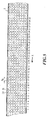
- FIG Fig. 5 is shown schematically, a punching pattern in which the center of the Punched out lines 34, 35 lie transversely and parallel to the web direction run.
- the degree of utilization i.e. H. the share of the punched area in the Total area, is between 50% and 55%.
- the diameters of the punched-out areas in the illustrated nonwoven inserts for coffee powder capsules are approximately 10 mm to 50 mm, preferably approximately 20 mm, the distance A x in the web direction between the punched-out areas is between 25 and 30 mm, the distance A y across the web direction is between 22 and 26 mm.
- a polyurethane fleece made from Estane® with a basis weight of 50 grams per square meter (DIN 53854, d 100), a tensile strength in the longitudinal direction of 20 N / 5cm and in the transverse direction of 14 N / 5cm (DIN / EN 29073 T3), an elongation in the longitudinal direction of 210% and in the transverse direction of 265% (DIN / EN 29073 T3), with an air permeability of 450 l / m 2 / s (DIN 53887,200 Pa), a pore size of at least 17.9 ⁇ m, a maximum of 29 ⁇ m, an average of 23 ⁇ m (Coulter Porometer) and a thickness of 0.16 mm (DIN / EN ISO 9073-2: 1997-02 point 5.1 ), and at a melting temperature of 175 to 180
- speeds of 165 mm / s can be achieved in the Y direction with a transport path of 24.75 mm (carriage movement), and in the X direction with a transport path of 28.58 mm, speeds of 190 mm / s (feed of the filter material).
- a carriage movement can be carried out at a speed of 0.93m / s.
- the first belt can be moved gently at a feed speed of 107.17 mm / s in X- Can be transported without interrupting the process.
- the clock rates mentioned above could be realized with a sealing time of 200ms, and with a movement of the time for filter and carriage transport of 300 ms. This results in a cycle time of 705.88 ms per stroke and a cycle power of 61200 capsules / h.
Landscapes
- Engineering & Computer Science (AREA)
- Mechanical Engineering (AREA)
- Containers And Plastic Fillers For Packaging (AREA)
Applications Claiming Priority (2)
| Application Number | Priority Date | Filing Date | Title |
|---|---|---|---|
| CH7392003 | 2003-04-25 | ||
| CH7392003 | 2003-04-25 |
Publications (2)
| Publication Number | Publication Date |
|---|---|
| EP1471012A2 true EP1471012A2 (fr) | 2004-10-27 |
| EP1471012A3 EP1471012A3 (fr) | 2005-01-12 |
Family
ID=32932335
Family Applications (1)
| Application Number | Title | Priority Date | Filing Date |
|---|---|---|---|
| EP04405230A Withdrawn EP1471012A3 (fr) | 2003-04-25 | 2004-04-15 | Procédé et dispositif pour fabriquer des récipients en forme de gobelet à partir des bandes de matériau |
Country Status (1)
| Country | Link |
|---|---|
| EP (1) | EP1471012A3 (fr) |
Cited By (12)
| Publication number | Priority date | Publication date | Assignee | Title |
|---|---|---|---|---|
| EP1568451A1 (fr) * | 2004-02-27 | 2005-08-31 | Ideacorp AG | Procédé et dispositif pour découper une matière filtrante |
| EP1849715A1 (fr) * | 2006-04-24 | 2007-10-31 | Nestec S.A. | Cartouche pour la préparation d'une boisson avec élement d'étanchéité et son procédé de fabrication |
| WO2012010317A1 (fr) * | 2010-07-22 | 2012-01-26 | Krüger Gmbh & Co. Kg | Capsule de portion avec identifiant |
| US10343838B2 (en) | 2012-06-18 | 2019-07-09 | K-Fee System Gmbh | Portion capsule and use of same for producing a beverage |
| US10472165B2 (en) | 2012-12-14 | 2019-11-12 | K-Fee System Gmbh | Portion capsule and method for producing a beverage by means of a portion capsule |
| US10669093B2 (en) | 2015-02-27 | 2020-06-02 | K-Fee System Gmbh | Single serve capsule comprising a filter element connected thereto by sealing |
| US10737876B2 (en) | 2015-07-13 | 2020-08-11 | K-Fee System Gmbh | Filter element having a cut-out |
| EP3792197A1 (fr) * | 2010-09-22 | 2021-03-17 | K-fee System GmbH | Capsule et procédé de préparation d'une boisson à l'aide d'une capsule |
| US11045035B2 (en) | 2015-09-18 | 2021-06-29 | K-Fee System Gmbh | Adapter for a single serve capsule |
| US11084650B2 (en) | 2015-06-10 | 2021-08-10 | K-Fee System Gmbh | Portion capsule with a three-ply nonwoven fabric |
| US12227323B2 (en) | 2018-07-27 | 2025-02-18 | Gcs German Capsule Solution Gmbh | Method for producing a portion capsule |
| US12459728B2 (en) | 2018-11-22 | 2025-11-04 | Gcs German Capsule Solution Gmbh | Seal for a single serve capsule |
Family Cites Families (4)
| Publication number | Priority date | Publication date | Assignee | Title |
|---|---|---|---|---|
| DE3482814D1 (de) * | 1983-10-17 | 1990-08-30 | Showa Denko Kk | Behaelter und verfahren zu seiner herstellung. |
| US5298267A (en) * | 1991-07-05 | 1994-03-29 | The Procter & Gamble Company | Coffee filter pack |
| JP2000262405A (ja) * | 1999-03-18 | 2000-09-26 | Soc Prod Nestle Sa | 飲料抽出用密封カートリッジ |
| DK1190959T3 (da) * | 2000-09-26 | 2004-06-28 | Nestle Sa | Lukket indsats, der er beregnet til fremstilling af en drik ved udtrækning under tryk |
-
2004
- 2004-04-15 EP EP04405230A patent/EP1471012A3/fr not_active Withdrawn
Cited By (40)
| Publication number | Priority date | Publication date | Assignee | Title |
|---|---|---|---|---|
| EP1914048A3 (fr) * | 2004-02-27 | 2008-12-10 | Nestec S.A. | Procédé et dispositif destinés à estampiller un matériau de filtre |
| EP1568451A1 (fr) * | 2004-02-27 | 2005-08-31 | Ideacorp AG | Procédé et dispositif pour découper une matière filtrante |
| US8161866B2 (en) | 2006-04-24 | 2012-04-24 | Nestec S.A. | Capsule for preparation of a beverage with a sealing member attached thereto and method of producing the same |
| EP1849715A1 (fr) * | 2006-04-24 | 2007-10-31 | Nestec S.A. | Cartouche pour la préparation d'une boisson avec élement d'étanchéité et son procédé de fabrication |
| WO2007122206A1 (fr) * | 2006-04-24 | 2007-11-01 | Nestec S.A. | Capsule de preparation d'une boisson avec organe d'etancheite attache sur la capsule et procede de fabrication de cette capsule |
| CN101432207B (zh) * | 2006-04-24 | 2010-11-24 | 雀巢产品技术援助有限公司 | 用于制备饮料的附装有密封件的胶囊及其制造方法 |
| US10994923B2 (en) | 2010-07-22 | 2021-05-04 | K-Fee System Gmbh | Portion capsule having an identifier |
| US11230430B2 (en) | 2010-07-22 | 2022-01-25 | K-Fee System Gmbh | Portion capsule having an identifier |
| RU2581002C2 (ru) * | 2010-07-22 | 2016-04-10 | К-Фее Зюстем Гмбх | Порционная капсула с идентификатором |
| CN103476686B (zh) * | 2010-07-22 | 2016-08-31 | K-Fee系统股份有限公司 | 具有标识符的分配胶囊 |
| CN105996782A (zh) * | 2010-07-22 | 2016-10-12 | K-Fee系统股份有限公司 | 具有标识符的分配胶囊 |
| US11919703B2 (en) | 2010-07-22 | 2024-03-05 | K-Fee System Gmbh | Portion capsule having an identifier |
| US11820586B2 (en) | 2010-07-22 | 2023-11-21 | K-Fee System Gmbh | Portion capsule having an identifier |
| US11667465B2 (en) | 2010-07-22 | 2023-06-06 | K-Fee System Gmbh | Portion capsule having an identifier |
| US11554910B2 (en) | 2010-07-22 | 2023-01-17 | K-Fee System Gmbh | Portion capsule having an identifier |
| US10858177B2 (en) | 2010-07-22 | 2020-12-08 | K-Fee System Gmbh | Portion capsule having an identifier |
| US10858176B2 (en) | 2010-07-22 | 2020-12-08 | K-Fee System Gmbh | Portion capsule having an identifier |
| US10870531B2 (en) | 2010-07-22 | 2020-12-22 | K-Fee System Gmbh | Portion capsule having an identifier |
| US11548722B2 (en) | 2010-07-22 | 2023-01-10 | K-Fee System Gmbh | Portion capsule having an identifier |
| US20210086986A1 (en) | 2010-07-22 | 2021-03-25 | K-Fee System Gmbh | Portion capsule having an identifier |
| WO2012010317A1 (fr) * | 2010-07-22 | 2012-01-26 | Krüger Gmbh & Co. Kg | Capsule de portion avec identifiant |
| US11542094B2 (en) | 2010-07-22 | 2023-01-03 | K-Fee System Gmbh | Portion capsule having an identifier |
| US11465829B2 (en) | 2010-07-22 | 2022-10-11 | K-Fee System Gmbh | Portion capsule having an identifier |
| CN103476686A (zh) * | 2010-07-22 | 2013-12-25 | K-Fee系统股份有限公司 | 具有标识符的分配胶囊 |
| US11254491B2 (en) | 2010-07-22 | 2022-02-22 | K-Fee System Gmbh | Portion capsule having an identifier |
| US11465830B2 (en) | 2010-07-22 | 2022-10-11 | K-Fee System Gmbh | Portion capsule having an identifier |
| EP4056499A1 (fr) * | 2010-09-22 | 2022-09-14 | K-fee System GmbH | Capsule indivivuelle et procédé de préparation d'une boisson à l'aide d'une capsule indivivuelle |
| EP3792197A1 (fr) * | 2010-09-22 | 2021-03-17 | K-fee System GmbH | Capsule et procédé de préparation d'une boisson à l'aide d'une capsule |
| US11312567B2 (en) | 2012-06-18 | 2022-04-26 | K-Fee System Gmbh | Portion and method for producing a beverage by means of a portion capsule |
| US12151876B2 (en) | 2012-06-18 | 2024-11-26 | K-Fee System Gmbh | Methods of making and using a portion capsule |
| US10343838B2 (en) | 2012-06-18 | 2019-07-09 | K-Fee System Gmbh | Portion capsule and use of same for producing a beverage |
| US11702276B2 (en) | 2012-06-18 | 2023-07-18 | K-Fee System Gmbh | Portion capsule for preparing a beverage |
| US10472165B2 (en) | 2012-12-14 | 2019-11-12 | K-Fee System Gmbh | Portion capsule and method for producing a beverage by means of a portion capsule |
| US10669093B2 (en) | 2015-02-27 | 2020-06-02 | K-Fee System Gmbh | Single serve capsule comprising a filter element connected thereto by sealing |
| US11084650B2 (en) | 2015-06-10 | 2021-08-10 | K-Fee System Gmbh | Portion capsule with a three-ply nonwoven fabric |
| US11498750B2 (en) | 2015-07-13 | 2022-11-15 | Gcs German Capsule Solution Gmbh | Filter element having a cut-out |
| US10737876B2 (en) | 2015-07-13 | 2020-08-11 | K-Fee System Gmbh | Filter element having a cut-out |
| US11045035B2 (en) | 2015-09-18 | 2021-06-29 | K-Fee System Gmbh | Adapter for a single serve capsule |
| US12227323B2 (en) | 2018-07-27 | 2025-02-18 | Gcs German Capsule Solution Gmbh | Method for producing a portion capsule |
| US12459728B2 (en) | 2018-11-22 | 2025-11-04 | Gcs German Capsule Solution Gmbh | Seal for a single serve capsule |
Also Published As
| Publication number | Publication date |
|---|---|
| EP1471012A3 (fr) | 2005-01-12 |
Similar Documents
| Publication | Publication Date | Title |
|---|---|---|
| DE19515517C2 (de) | Verfahren und Vorrichtung zur kontinuierlichen Herstellung von Längenabschnitten aus einem Strang Flüssigkeit absorbierenden Materials sowie dessen Verwendung | |
| DD287451A5 (de) | Form-fuell-verschliessmaschine zur automatischen herstellung einer vorbestimmten anzahl gefuellter und verschlossener fertigverpackungen | |
| DE3874302T2 (de) | Vorrichtung zum erzeugen und verpacken von heftpflaster. | |
| DE3637877A1 (de) | Verfahren und vorrichtung zum herstellen von beuteln | |
| EP1046479A1 (fr) | Dispositif pour la perforation et le gaufrage d'un matériau en feuille | |
| DE68909766T2 (de) | Verfahren und Vorrichtung zum Herstellen von abgemessene Mengen von Produkten enthaltenden Beuteln bestimmter Form. | |
| EP1839825A1 (fr) | Procédé et appareil de production pour des feuilles perforées | |
| DE2065712A1 (de) | Tiefziehmaschine zum herstellen von seitenwandverstaerkten behaeltern | |
| DE102010026801A1 (de) | Vorrichtung zum Abteilen von Verpackungen aus einer Trägerbahn mit hintereinander angeordneten Blisterblasen | |
| EP2409939B2 (fr) | Installation de pliage et d'agrafage pour bandes de carton ondulé | |
| EP2289660B1 (fr) | Dispositif et procédé de découpe pour des matériels TDS ou ODF avec deux paires de rouleaux d'entraînement | |
| EP4721950A1 (fr) | Procédé de fabrication d'un matériau en bande extrudé en matière plastique, matériau en bande extrudé et emballage de transport | |
| WO2017108415A1 (fr) | Dispositif et procédé de fabrication de produits non-tissés par découpage par rotation | |
| EP1568451B1 (fr) | Procédé et dispositif pour découper une matière filtrante | |
| DE19751983B4 (de) | Bahnförmiges Material mit Perforation, aus dem Material hergestellte Verpackung, Verfahren zum Herstellen der Perforation in dem Material sowie Vorrichtung zur Durchführung des Verfahrens | |
| DE19509863A1 (de) | Verfahren und Vorrichtung zur Verformung von Papier und Karton | |
| DE10000297A1 (de) | Verfahren und Vorrichtung zum Herstellen und Einwickeln eines aus mehreren Einzelportionen bestehenden weichplastischen Körpers, vorzugsweise eines fetthaltigen Produktes, wie Butter, Margarine o. dgl. | |
| DE102005047646B4 (de) | Vorrichtung zum Ausstanzen von Zuschnitten aus bahnförmigem Material | |
| WO1990004062A1 (fr) | Procede et installation de fabrication de corps textiles plats | |
| DE102022129118A1 (de) | Vorrichtung und Verfahren zum Umformen eines Verpackungselements | |
| DE2656421C2 (fr) | ||
| DE60314567T2 (de) | Verfahren und Maschine für integrierte Formung zum Herstellen von nichtentformbaren Bechern | |
| DE2748228C2 (de) | Verfahren zum fortlaufenden Transport von durch einen Stanzstempel ausgestanzten einzelnen Stanzteilen für elektrische Geräte zu einer Stapelvorrichtung und Vorrichtung zur Durchführung des Verfahrens | |
| DE4418063C2 (de) | Maschine zum Herstellen von tiefgezogenen Bechern mit Fuß | |
| EP2014155B1 (fr) | Procédé destiné à la fabrication de tranches de fromage, tranches de fromage ainsi fabriquées et dispositif d'exécution du procédé |
Legal Events
| Date | Code | Title | Description |
|---|---|---|---|
| PUAI | Public reference made under article 153(3) epc to a published international application that has entered the european phase |
Free format text: ORIGINAL CODE: 0009012 |
|
| AK | Designated contracting states |
Kind code of ref document: A2 Designated state(s): AT BE BG CH CY CZ DE DK EE ES FI FR GB GR HU IE IT LI LU MC NL PL PT RO SE SI SK TR |
|
| AX | Request for extension of the european patent |
Extension state: AL HR LT LV MK |
|
| PUAL | Search report despatched |
Free format text: ORIGINAL CODE: 0009013 |
|
| AK | Designated contracting states |
Kind code of ref document: A3 Designated state(s): AT BE BG CH CY CZ DE DK EE ES FI FR GB GR HU IE IT LI LU MC NL PL PT RO SE SI SK TR |
|
| AX | Request for extension of the european patent |
Extension state: AL HR LT LV MK |
|
| 17P | Request for examination filed |
Effective date: 20050507 |
|
| AKX | Designation fees paid |
Designated state(s): AT BE BG CH CY CZ DE DK EE ES FI FR GB GR HU IE IT LI LU MC NL PL PT RO SE SI SK TR |
|
| RAP1 | Party data changed (applicant data changed or rights of an application transferred) |
Owner name: NESTEC S.A. |
|
| 17Q | First examination report despatched |
Effective date: 20120627 |
|
| STAA | Information on the status of an ep patent application or granted ep patent |
Free format text: STATUS: THE APPLICATION HAS BEEN WITHDRAWN |
|
| 18W | Application withdrawn |
Effective date: 20140108 |