EP1568451A1 - Procédé et dispositif pour découper une matière filtrante - Google Patents
Procédé et dispositif pour découper une matière filtrante Download PDFInfo
- Publication number
- EP1568451A1 EP1568451A1 EP05405211A EP05405211A EP1568451A1 EP 1568451 A1 EP1568451 A1 EP 1568451A1 EP 05405211 A EP05405211 A EP 05405211A EP 05405211 A EP05405211 A EP 05405211A EP 1568451 A1 EP1568451 A1 EP 1568451A1
- Authority
- EP
- European Patent Office
- Prior art keywords
- material web
- insert
- cutting edge
- punching
- cutting
- Prior art date
- Legal status (The legal status is an assumption and is not a legal conclusion. Google has not performed a legal analysis and makes no representation as to the accuracy of the status listed.)
- Granted
Links
- 238000000034 method Methods 0.000 title claims abstract description 54
- 238000004080 punching Methods 0.000 title claims description 64
- 238000001914 filtration Methods 0.000 title 1
- 238000005520 cutting process Methods 0.000 claims abstract description 154
- 239000000463 material Substances 0.000 claims abstract description 90
- 230000008569 process Effects 0.000 claims abstract description 20
- 238000002844 melting Methods 0.000 claims abstract description 6
- 230000008018 melting Effects 0.000 claims abstract description 6
- 239000012611 container material Substances 0.000 claims description 43
- 238000007789 sealing Methods 0.000 claims description 35
- 239000002775 capsule Substances 0.000 claims description 21
- 238000004519 manufacturing process Methods 0.000 claims description 11
- 239000000843 powder Substances 0.000 claims description 10
- 229920002635 polyurethane Polymers 0.000 claims description 7
- 239000004814 polyurethane Substances 0.000 claims description 7
- 238000006073 displacement reaction Methods 0.000 claims description 6
- 230000004913 activation Effects 0.000 claims description 4
- 230000001154 acute effect Effects 0.000 claims description 4
- 239000003566 sealing material Substances 0.000 claims description 4
- 239000004721 Polyphenylene oxide Substances 0.000 claims description 2
- 239000004433 Thermoplastic polyurethane Substances 0.000 claims description 2
- 230000035699 permeability Effects 0.000 claims description 2
- 229920000728 polyester Polymers 0.000 claims description 2
- 229920000570 polyether Polymers 0.000 claims description 2
- 239000011148 porous material Substances 0.000 claims description 2
- 230000001360 synchronised effect Effects 0.000 claims description 2
- 229920002803 thermoplastic polyurethane Polymers 0.000 claims description 2
- 238000010438 heat treatment Methods 0.000 description 8
- 230000000694 effects Effects 0.000 description 5
- 238000000926 separation method Methods 0.000 description 5
- 239000011248 coating agent Substances 0.000 description 4
- 238000000576 coating method Methods 0.000 description 4
- 230000006835 compression Effects 0.000 description 4
- 238000007906 compression Methods 0.000 description 4
- 229910052782 aluminium Inorganic materials 0.000 description 3
- XAGFODPZIPBFFR-UHFFFAOYSA-N aluminium Chemical compound [Al] XAGFODPZIPBFFR-UHFFFAOYSA-N 0.000 description 3
- 230000001419 dependent effect Effects 0.000 description 2
- 239000000835 fiber Substances 0.000 description 2
- 238000009413 insulation Methods 0.000 description 2
- 229910052751 metal Inorganic materials 0.000 description 2
- 239000002184 metal Substances 0.000 description 2
- XLYOFNOQVPJJNP-UHFFFAOYSA-N water Substances O XLYOFNOQVPJJNP-UHFFFAOYSA-N 0.000 description 2
- 241000047428 Halter Species 0.000 description 1
- 206010053615 Thermal burn Diseases 0.000 description 1
- ATJFFYVFTNAWJD-UHFFFAOYSA-N Tin Chemical compound [Sn] ATJFFYVFTNAWJD-UHFFFAOYSA-N 0.000 description 1
- NIXOWILDQLNWCW-UHFFFAOYSA-N acrylic acid group Chemical group C(C=C)(=O)O NIXOWILDQLNWCW-UHFFFAOYSA-N 0.000 description 1
- 230000009471 action Effects 0.000 description 1
- 238000000071 blow moulding Methods 0.000 description 1
- 238000010411 cooking Methods 0.000 description 1
- 239000000645 desinfectant Substances 0.000 description 1
- 238000005553 drilling Methods 0.000 description 1
- 239000003651 drinking water Substances 0.000 description 1
- 235000020188 drinking water Nutrition 0.000 description 1
- 238000005485 electric heating Methods 0.000 description 1
- 235000013305 food Nutrition 0.000 description 1
- 238000012432 intermediate storage Methods 0.000 description 1
- 238000002955 isolation Methods 0.000 description 1
- 210000003127 knee Anatomy 0.000 description 1
- 239000007788 liquid Substances 0.000 description 1
- 239000000155 melt Substances 0.000 description 1
- 230000003287 optical effect Effects 0.000 description 1
- 239000004033 plastic Substances 0.000 description 1
- 229920003023 plastic Polymers 0.000 description 1
- 238000002360 preparation method Methods 0.000 description 1
- 230000000284 resting effect Effects 0.000 description 1
- 238000007493 shaping process Methods 0.000 description 1
- 239000000126 substance Substances 0.000 description 1
- 239000002966 varnish Substances 0.000 description 1
Images


Classifications
-
- B—PERFORMING OPERATIONS; TRANSPORTING
- B31—MAKING ARTICLES OF PAPER, CARDBOARD OR MATERIAL WORKED IN A MANNER ANALOGOUS TO PAPER; WORKING PAPER, CARDBOARD OR MATERIAL WORKED IN A MANNER ANALOGOUS TO PAPER
- B31B—MAKING CONTAINERS OF PAPER, CARDBOARD OR MATERIAL WORKED IN A MANNER ANALOGOUS TO PAPER
- B31B50/00—Making rigid or semi-rigid containers, e.g. boxes or cartons
- B31B50/74—Auxiliary operations
- B31B50/81—Forming or attaching accessories, e.g. opening devices, closures or tear strings
-
- B—PERFORMING OPERATIONS; TRANSPORTING
- B26—HAND CUTTING TOOLS; CUTTING; SEVERING
- B26F—PERFORATING; PUNCHING; CUTTING-OUT; STAMPING-OUT; SEVERING BY MEANS OTHER THAN CUTTING
- B26F1/00—Perforating; Punching; Cutting-out; Stamping-out; Apparatus therefor
- B26F1/38—Cutting-out; Stamping-out
- B26F1/3846—Cutting-out; Stamping-out cutting out discs or the like
-
- B—PERFORMING OPERATIONS; TRANSPORTING
- B26—HAND CUTTING TOOLS; CUTTING; SEVERING
- B26D—CUTTING; DETAILS COMMON TO MACHINES FOR PERFORATING, PUNCHING, CUTTING-OUT, STAMPING-OUT OR SEVERING
- B26D7/00—Details of apparatus for cutting, cutting-out, stamping-out, punching, perforating, or severing by means other than cutting
- B26D7/08—Means for treating work or cutting member to facilitate cutting
- B26D7/10—Means for treating work or cutting member to facilitate cutting by heating
-
- B—PERFORMING OPERATIONS; TRANSPORTING
- B26—HAND CUTTING TOOLS; CUTTING; SEVERING
- B26F—PERFORATING; PUNCHING; CUTTING-OUT; STAMPING-OUT; SEVERING BY MEANS OTHER THAN CUTTING
- B26F1/00—Perforating; Punching; Cutting-out; Stamping-out; Apparatus therefor
- B26F1/38—Cutting-out; Stamping-out
- B26F1/40—Cutting-out; Stamping-out using a press, e.g. of the ram type
-
- B—PERFORMING OPERATIONS; TRANSPORTING
- B26—HAND CUTTING TOOLS; CUTTING; SEVERING
- B26D—CUTTING; DETAILS COMMON TO MACHINES FOR PERFORATING, PUNCHING, CUTTING-OUT, STAMPING-OUT OR SEVERING
- B26D5/00—Arrangements for operating and controlling machines or devices for cutting, cutting-out, stamping-out, punching, perforating, or severing by means other than cutting
- B26D5/08—Means for actuating the cutting member to effect the cut
- B26D5/18—Toggle-link means
Definitions
- the present invention relates to a method and a device for the Punching out inserts from a nonwoven insert sheet Material.
- the invention is particularly in the field of production of coffee capsules with inserts made of polyurethane fleece.
- containers in which moisture-sensitive powder is contained, provided with an insert which absorbs the moisture and keeps the powder dry.
- Other applications are to provide inserts which release a substance into the main space upon activation, e.g. with capsules or cups for drinking water could be the case, in which after a piercing o.ä. a disinfectant is dispensed in controlled doses.
- Self-sealing inserts are also used for coffee powder capsules. There the deposits are usually provided on the bottom of the coffee powder capsules.
- Coffee preparation the capsules in the coffee machine with a needle or with 3 Stitch gauge is tapped on the floor area and water is thrown through the floor Coffee powder introduced into the capsules. After the coffee has been prepared and the needle has been pulled out again, the coffee powder capsules remain due to the self-sealing insert tight. This will avoid that when removing the coffee powder capsules leak remains of hot cooking water and the Users can scald and contaminate the capsule chamber of the Coffee machines are prevented.
- the containers are made of a container material web, for example a Aluminum band, shaped. They are punched out of a train and then by forming, such as deep drawing or blow molding, manufactured. The Inserts themselves are punched out of a band-shaped Einlagenmaterialbahn, before they are sealed onto the aluminum strip.
- the punching and introduction Of the deposits is, especially with self-sealing deposits, often with technical Difficulties: Self-sealing inserts are subject to tensile stress a high elasticity, so they when drilling through the container wall together with the Insert by their own elasticity, the hole immediately seal.
- the Surfaces of such self-sealing inserts have a certain adhesiveness, so that the hole edges in a perforation of the self-sealing inserts stick together and reinforce the seal.
- the high elasticity of the Einlagenmaterials on the one hand with the result that a feed movement of the Einlagenmaterialbandes can only be done at low speed or that only low tensile forces can act on the deposit material, on the other hand it leads along with other material properties, that the stamping process typically must be carried out consuming, so that the punching in particular always guaranteed clean at high production speeds.
- the invention is therefore based on the object, a method, respectively a Device to provide a reliable and high Speeds-enabled punching process, even when punching Inserts made of an insert material web made of a difficult-to-machine nonwoven Material.
- the solution of this problem is achieved in that the method in a first Step the pad material web between a punched hole having Cutting die and one in the punching area to the punching opening tapered Cutting edge having corresponding cutting edge is performed, and in a second Step down the cutting die and the cutting edge in one direction substantially be fed to each other perpendicular to the plane of the Einlagenmaterialbahn, that the cutting edge partially engages in the punching opening of the cutting die and the intermediate liner material web separated to form the insert with the cutting edge and / or cutting die maintained at a temperature in which an at least partial melting of the deposit material takes place.
- the core of the invention thus consists in the mechanical punching process by the Application of increased temperature support, and thus the classic way to facilitate and improve only mechanically performed punching process.
- such deposits are typically by a Ball-head cutting edge, which can be cut off when the insert material is clamped within the cutting die to ever sufficient separation effect produce, punched.
- a large punching force required to produce a sufficient effect at all can be reduced according to the punching force, since smallest Fibers are melted off.
- the insert material web is a polyurethane nonwoven, preferably of a thermoplastic polyurethane based on polyester or polyether, in which case particularly preferably the cutting edge and / or the cutting die are at a temperature in the region of 75 ° -90 ° C is / are kept.
- the polyurethane nonwoven is a polyurethane nonwoven with an air permeability of more than 300 l / m 2 / s and a pore size in the range of 10 to 40 mm, preferably at a thickness of in the range of 0.1 to 0.3 mm. Also, such material can be punched very efficiently with the proposed method.
- the method performed using a cutting die which is a substantially cylindrical, preferably circular cylindrical punch opening, and wherein the Cutting surface of the cutting edge with the cylinder axis at an acute angle, in particular preferably in the range of 30 to 60 ° (preferably about 45 °) includes.
- the cutting edge designed so that they are in contact with the cutting surface with the Cutting die only by a few tenths of a millimeter, for example, only 1 / 10mm in the Punching opening of the cutting die engages.
- the cutting edge as a ring cutting, which within the Cutting surface has an opening through which a punch perpendicular to Level of the insert material web is guided, wherein in a third step of the Method of the punch discharges the insert through the punched opening, and wherein in particular, this removal preferably takes place on a second material web.
- the Insert can preferably be guided through the punch opening and in contact be brought with the second material web, with particular preference the Insert is connected to the second material web.
- the heating of cutting edge and / or cutting die proves It is advantageous according to a further preferred embodiment, this induce inductively. But it is also possible to use other heating methods use such as electric heating, optical heating and the like.
- the heating should at least at the moment of the merger of Cutting edge and / or cutting die to be ensured at the desired temperature, this preferably in the range of 50 to 150 ° C, particularly preferably in the range of 75 to 100 ° C.
- the cutting edge is kept at this temperature.
- the method is a method for producing cup-shaped, with a deposit Containers (in particular of coffee capsules), which is characterized in that the inserts are punched out before forming the cup-shaped container on be applied to the places where the container in a subsequent Operation are made by forming, and that the cup-shaped container then punched out of a container material web and then in a Shaping process are formed, wherein preferably in a step between 6 and 12 Inserts, particularly preferably 8 deposits are punched out.
- the deposits will be preferably punched out of a Einlagenmaterialbahn, and the Einlagenmaterialbahn and the container material web are so one above the other fed to the deposits immediately after their punching out of the Einlagenmaterialbahn on the underneath resp. overlying container material web applied and can be connected to this.
- the present invention also relates to a device in particular for carrying out a method as described above.
- the Device is for punching out deposits from a Einlagematerialbahn a non-woven material, and includes a cutting die with a punch opening and a cutting edge between which the insert material web is disconnected.
- the device is characterized in particular in that the Cutting edge has a cutting area tapering towards the punch opening in the punching area, that the cutting die and the cutting edge are substantially perpendicular in one direction are stored to the level of Einlagenmaterialbahn such that they are fed to each other can be, with the cutting edge in the punching opening of the cutting die at least partially engages and the intermediate Einlagenmaterialbahn under training the insert is separated, wherein means are arranged, by means of which the Cutting edge and / or the cutting die are kept at a temperature at which at least a partial melting of the deposit material takes place.
- the cutting die has a substantially cylindrical, preferably circular cylindrical punch opening, and the cutting surface of the cutting edge (16) closes with the associated cylinder axis an acute angle, particularly preferably in Range of 30 to 60 °, preferably in the range of 45 °, a.
- the cutting edge as a cutting edge, which within the Cutting surface has an opening through which a punch perpendicular to Level of the insert material web can be performed.
- the stamp is added provided, the insert through the punch opening substantially immediately after the To dissipate punching process, preferably this discharge, preferably in one linear movement (eg, parallel to the relative direction of movement of the cutting edge and Schneidmatrize), takes place on a second material web, and wherein in particular Preferably further means are provided, by means of which the insert with the second material web can be connected.
- the funds may be a Seal heating act, with the help of which the insert with the second material web in a marriage sealing process can be connected. It is particularly preferred the sealing heater on the side facing away from the insert of the second material web arranged, and the seal heater is maintained at a temperature which a Activation of a side of the second material web facing the insert arranged sealing material (can on the insert or on the second material web already be provided) triggers.
- the proposed device can be used in particular in the field of Production of cup-shaped containers provided with a liner such as Coffee powder capsules are used.
- a Einlagenmaterialbahn a the deposit material web in a work area overlapping container material web and a punching device arranged in the working area, through which the Inserts on stamping positions arranged in a predetermined application pattern punched out and in predetermined container positions on the container material web can be applied, wherein preferably a feed device is present by which the punching device and the Einlagenmaterialbahn at least at one part the displacement steps substantially transverse to the web direction of Einlagenmaterialbahn are movable relative to each other movable.
- a feed device is present by which the punching device and the Einlagenmaterialbahn at least at one part the displacement steps substantially transverse to the web direction of Einlagenmaterialbahn are movable relative to each other movable.
- the seal stamp on means especially in the form of means for Applying a negative pressure (e.g., vacuum lines with openings on the Stamp top, wherein the vacuum depending on the punching cycle respectively in essential only applied while transporting to a second web takes place), by means of which the insert between the punching and the application on the second web can be held on the seal.
- a negative pressure e.g., vacuum lines with openings on the Stamp top, wherein the vacuum depending on the punching cycle respectively in essential only applied while transporting to a second web takes place
- the cutting die in a first stationary plane (in a die holder), wherein above this first stationary plane, the second Material web (eg container material web) and above this second material web a sealed heater (for fixing the deposits on the container material web) are arranged.
- first stationary plane in a die holder
- the second Material web eg container material web
- a sealed heater for fixing the deposits on the container material web
- Ring cutting edge formed cutting edge for partial engagement in the cutting die designed
- a Sealing stamp is mounted axially displaceable within the annular cutting edge to this.
- a large number of coffee capsules may be prove advantageous to arrange a plurality of cutting dies in a first plane, and to arrange a corresponding number of blades in a second plane, and the first and second levels synchronized with each other during the punching process move.
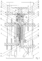
- Fig. 1 shows an axial schematic section through a punching device according to a first embodiment.
- the punching device stands on a base plate 1, on which guide columns 2 are attached.
- a punching device comprises usually four such guide columns 2, but with several punching devices can be performed by such a group of four guide columns 2 (see. below in connection with Figs. 3 and 4).
- the base plate 1 respectively arranged on the guide columns 2 are fixed on the one hand, the cover plate. 4 and a die holder 11 arranged below it.
- the cover plate 4 and the Die holder 11 may be fixedly connected to the guide columns 2 for fixing, But also on other fastening devices in relation to the Guide columns 2 to be fixed in place.
- the punching device described in the context of this embodiment is u.a. designed in a combined process initially from a Einlagematerialbahn 26 a liner 39 aus punch, and this deposit directly then apply to a container material web 27. To this direct transfer too ensure the container material web 27 above the die holder 11 and in a sense, on this resting led. Below the die holder is the Insert material web 26 out.
- the moving elements of the punching device are now below the die holder 11 arranged.
- the punching device is on the right half-side in the open state shown, and on the left half-side in the closed state immediately at Applying the insert to the sealing film 27, d. H. on the container material web.
- the movable elements of the punching devices comprise a lower holder 5, which via a toggle 24 on the guide columns 2 in the vertical direction is slidably mounted.
- Another movable element is the upper holder 6 to call, which also is slidably mounted on the guide columns 2 in the vertical direction.
- the upper Holder 6 can be moved relative to the lower holder 5 to a certain extent and this relative mobility is for a functioning of the stamping process crucial.
- the upper holder 6 is slidable via a guide rod 10 with the lower Holder 5 connected.
- the guide rod arranged parallel to the guide columns 2 10 is fixedly connected to the upper holder 6 and is at the lower holder 5 via a Guide holder 7, in which a sliding bearing 9 is arranged, slidably guided.
- a Adjusting nut 30 determined. This maximum distance is determined by at least one Cutting compression spring 23 forced. In other words, the upper level 6 only approximated against the spring force of the cutting compression spring 23 to the lower level 5 and this only up to another stop, then, namely, when the Guide rod 10 and the adjusting nut 30 with the surface of the lower Halters 5 comes into contact.
- an insulation 12 is first arranged on which then a bobbin 13 is placed.
- an electric coil 14 is arranged, which serves to a above the bobbin 13 arranged annular cutting edge 16 to heat inductively.
- a temperature sensor 29th is also arranged.
- the annular cutting edge 16 is connected via a clamping ring 15 on the bobbin 13 attached.
- the annular cutting edge 16 is essentially substantially cylindrical on the inside cut out circular ring formed, the cutting die 20 facing Outer surface, the cutting surface 44, tapered, d. H. it forms a cutting tip.
- the cutting surface 44 closes with the axis of the annular cutting edge 16 an angle of 30-45 °.
- the cutting tip of the annular cutting edge 16 is the Adjusted inside diameter of the cutting die 20 attached to the die holder 11.
- the cutting die 20 is made, just like the annular cutting edge 16 of a hardened Metal and is interchangeable and formed in the form of a circular ring.
- the Cutting dies 20 also has a cylindrical central opening whose Diameter but about 2/10 mm larger than the diameter of the cutting tip Ring cutting edge 16.
- the annular cutting edge 16 thus moves in a succession of the Ring cutting 16 on the cutting die 20 into the Schneidmatrize20 easy, and
- the material to be separated is on the one hand by the cutting tip and on the other clamped between the cutting surface 44 and the inner edge of the cutting die 20 respectively. separated.
- This the plunger 21st is on the lower side first in the guide holder 7 of the lower holder 5 in one Slide bearing guided.
- a sealing compression spring 22 clamped upward d. H. the plunger 21 can only against the Spring force of the sealing compression spring 22 against the lower holder 25 down be moved.
- the Seal 17 arranged, and this is firmly connected to the plunger 21.
- Sealing stamp 17 has in the area of the annular cutting edge 16 via a shoulder, which in a corresponding paragraph formed by the bobbin 13 and the Ring cutting 16 engages, so that the unit of seal stamp 17 and plunger 22 only can be inserted into the upper holder 6 until it reaches this paragraph.
- the Seal 17 set on the adjusting nut 25 such that the upper level of the Sealing stamp 17 substantially in a plane with the cutting tip of Ring cutting 16 comes to rest.
- a System provided with vacuum lines, which on the underside of the plunger 21st Vacuum is applied via a vacuum connection 28.
- the vacuum lines open at the upper-side inner surface of the seal stamp 17 in small holes, and serve the punched insert 39 in their transport up to the Keep container material web 27 on the seal 17 stamp.
- a sealing heater 18 is arranged Immediately above the cutting die 20 and between die holder 11 and Cover plate 4 is coaxial with the movable just described below arranged elements of the punch a sealing heater 18 is arranged. These Sealing heater 18 is attached via an insulation 19 on the cover plate 4.
- the Sealing heater 18 is formed substantially as a cylindrical punch, the is electrically maintained at a temperature which is a sealing of the inserts 39 allowed with the container material web 27. The sealed heater 18 is doing so above the container material web 27 arranged that between the container material web 27 and Seal heater 18 a distance of about 1/2 mm remains.
- the individual elements lower holder 5, upper holder 6 and plunger 21 with it fastened seal stamp 17 are in other words adjustable relative to each other displaceable and movable, and the mobility is described below on the basis of Description of the operation will be described in a punching operation.
- the punching device is in the open position on the right side State shown. In this open state, the annular cutting edge 16 of the Cutting die 20 spaced.
- the insert material web 26 is guided, namely Preferably, such that they neither the cutting die 20 nor the annular cutting edge 16 touched.
- Einlagematerialbahn in the present case, a train Polyurethane fleece made of Estane® with a basis weight of 50 grams per Square meters.
- a sealing film 27 respectively a Container material web led. It is a metal track resp. a tin from, for example, aluminum, which is already provided with a coating, which applying and simultaneously securing the inserts 39 on the Container material web 27 is allowed by simple local heating (typically if the coating is an acrylic based hot sealing varnish).
- the Coating must for this purpose at least on the seal heater 18th remote side on the container material web 27 may be present.
- the Container material web 27 is spaced from the seal heater 18, it should between seal heater and container material web at least a distance of 1/2 mm remain.
- Both the container material web 27 and the insert material web 26 have the reached desired position, via the toggle lever 24, the entire unit as it is shown in the right half-plane of Fig. 1, moved upward. After a corresponding displacement is first a contact between the annular cutting edge 16 (And optionally the surface of the seal stamp 17) with the insert material web 26 take place. Since the insert material web 26 is flexible, it becomes more in the other Displacement of seal punch 17 and cup 16 up and last against pressed the cutting die 20. At the moment in which the Einlagematerialbahn 26 between the annular cutting edge 16 and the cutting dies 20 is pressed, is a Separation of the insert material web to form the deposits 39 take place.
- this separation occurs due to the mechanical separation effect between Ring cutting 16 (respectively cutting surface 44) and cutting die 20 instead,
- a more extensive separation effect the heating of the annular cutting edge 16 is reached.
- the ring cutter 16 becomes at least at the moment of punching at a temperature in the range of 75-90 ° or held more thin, and accordingly thin fibers, which by the mechanical Effect can not be separated enough, separated by the action of heat.
- the Sealing heater 18, which at a temperature of about 160 ° or depending on Melting point of the sealing medium is held, now causes the deposit between Stamp 17 and container material web 27 respectively seal heater 18 pressed and is heated so that the arranged on the container material web 27 coating at least partially melts and a firm connection between deposit and Container material web 27 leads.
- the applied pressure is through the seal-pressure spring 22 determined.
- the toggle is stretched out in this position, and a further rotation then leads again to a movement apart of the punch.
- Container material web 27 and insert material web 26 can now move to the next one required position to be postponed.
- FIG. 2 Another embodiment of a punching device is shown in Fig. 2, wherein corresponding parts are the same as in Fig. 1. Accordingly, the following only the essential differences between Fig. 1 and 2 will be discussed.
- the die holder 11 and the cover plate 4 are not on the Guide columns 2 attached, but rather to other support columns 33rd Die Guide columns 2 are limited at their upper end via a closure plate 34, on which is typically the insert material web 26 is guided.
- the annular cutting edge 16 and the cutting die 20 in the case of Wear replaceable provided.
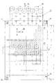
- FIG. 3 now shows a plan view of a device in which 8 inserts 39 simultaneously and synchronously by 8 punching devices as shown in Fig. 1 and Fig. 2nd are shown punched out.
- Fig. 3 is visible as the container material web 27 is transported in a first main feed direction 35, and the Einlagematerialbahn in a second main feed direction 36, which perpendicular to the first feed direction 35 is.
- two Einlagematerialbahnen 40 and 41 out parallel to each other and after a certain pattern (see Fig. 4) traveled.
- the procedure for sequential processing of individual punching positions in the insert material web 40 is referred to the method described in detail in CH 0739/03, and this This item is explicitly included in the disclosure.
- Fig. 3 Regarding the procedure for sequential processing of individual punching positions in the insert material web 40 is referred to the method described in detail in CH 0739/03, and this This item is explicitly included in the disclosure.
- FIG. 1 the container material web 27, which is completely filled with inserts 39, is shown, it becomes visible how the container material web, which has a width a of approximately 469 mm, is fitted with inserts 39 under maximum material utilization (the diameter 38 is 63.5 mm). This is achieved by the displacement pattern as indicated in the middle region by the sequence of the numbers within the illustrated liner web 43 while optimally utilizing the material of the liner web 43.
Landscapes
- Life Sciences & Earth Sciences (AREA)
- Forests & Forestry (AREA)
- Engineering & Computer Science (AREA)
- Mechanical Engineering (AREA)
- Physics & Mathematics (AREA)
- Optics & Photonics (AREA)
- Perforating, Stamping-Out Or Severing By Means Other Than Cutting (AREA)
- Electrical Discharge Machining, Electrochemical Machining, And Combined Machining (AREA)
- Processing And Handling Of Plastics And Other Materials For Molding In General (AREA)
- Containers And Plastic Fillers For Packaging (AREA)
- Filtering Materials (AREA)
Priority Applications (3)
| Application Number | Priority Date | Filing Date | Title |
|---|---|---|---|
| SI200530150T SI1568451T1 (sl) | 2004-02-27 | 2005-02-25 | Postopek in naprava za izrezovanje filtrskega materiala |
| EP08100430A EP1914048A3 (fr) | 2004-02-27 | 2005-02-25 | Procédé et dispositif destinés à estampiller un matériau de filtre |
| PL05405211T PL1568451T3 (pl) | 2004-02-27 | 2005-02-25 | Sposób i urządzenie do wykrawania materiału filtracyjnego |
Applications Claiming Priority (2)
| Application Number | Priority Date | Filing Date | Title |
|---|---|---|---|
| CH3332004 | 2004-02-27 | ||
| CH333042004 | 2004-02-27 |
Related Child Applications (1)
| Application Number | Title | Priority Date | Filing Date |
|---|---|---|---|
| EP08100430A Division EP1914048A3 (fr) | 2004-02-27 | 2005-02-25 | Procédé et dispositif destinés à estampiller un matériau de filtre |
Publications (2)
| Publication Number | Publication Date |
|---|---|
| EP1568451A1 true EP1568451A1 (fr) | 2005-08-31 |
| EP1568451B1 EP1568451B1 (fr) | 2008-01-16 |
Family
ID=34744474
Family Applications (2)
| Application Number | Title | Priority Date | Filing Date |
|---|---|---|---|
| EP08100430A Withdrawn EP1914048A3 (fr) | 2004-02-27 | 2005-02-25 | Procédé et dispositif destinés à estampiller un matériau de filtre |
| EP05405211A Expired - Lifetime EP1568451B1 (fr) | 2004-02-27 | 2005-02-25 | Procédé et dispositif pour découper une matière filtrante |
Family Applications Before (1)
| Application Number | Title | Priority Date | Filing Date |
|---|---|---|---|
| EP08100430A Withdrawn EP1914048A3 (fr) | 2004-02-27 | 2005-02-25 | Procédé et dispositif destinés à estampiller un matériau de filtre |
Country Status (7)
| Country | Link |
|---|---|
| EP (2) | EP1914048A3 (fr) |
| AT (1) | ATE383930T1 (fr) |
| DE (1) | DE502005002533D1 (fr) |
| DK (1) | DK1568451T3 (fr) |
| ES (1) | ES2298984T3 (fr) |
| PL (1) | PL1568451T3 (fr) |
| PT (1) | PT1568451E (fr) |
Cited By (3)
| Publication number | Priority date | Publication date | Assignee | Title |
|---|---|---|---|---|
| US20210086986A1 (en) | 2010-07-22 | 2021-03-25 | K-Fee System Gmbh | Portion capsule having an identifier |
| CN112677507A (zh) * | 2020-12-09 | 2021-04-20 | 南京精孔科技有限公司 | 一种epe发泡珍珠棉内衬包装材料及其制作加工方法 |
| CN118386301A (zh) * | 2024-06-24 | 2024-07-26 | 索菲亚家居股份有限公司 | 一种覆膜人造板的同步自动化脱膜与修边装置及方法 |
Families Citing this family (1)
| Publication number | Priority date | Publication date | Assignee | Title |
|---|---|---|---|---|
| JP7498639B2 (ja) * | 2020-10-16 | 2024-06-12 | 出光ユニテック株式会社 | フィルム片の打ち抜き接合装置、フィルムの製造装置、袋状容器の製造装置、フィルム片の打ち抜き接合方法、フィルムの製造方法および袋状容器の製造方法 |
Citations (6)
| Publication number | Priority date | Publication date | Assignee | Title |
|---|---|---|---|---|
| US3623209A (en) * | 1968-08-14 | 1971-11-30 | Zuehlke & Braendli Ag | Method for separating blanks from plastic sheets |
| US4823660A (en) * | 1986-02-20 | 1989-04-25 | Stelron Components Inc | Label cutting device and method |
| US20020015768A1 (en) * | 1999-03-18 | 2002-02-07 | Petr Masek | Sealed cartridge for making a beverage |
| DE10032458A1 (de) * | 2000-07-04 | 2002-07-25 | Rehau Ag & Co | Stanzwerkzeug zur Herstellung von Durchbrüchen in Werkstücken aus thermoplastischem Material |
| DE10208997A1 (de) * | 2002-02-28 | 2003-09-11 | Bosch Gmbh Robert | Verfahren und-Vorrichtung zum Stanzen von versiegelten becherartigen Behältern |
| EP1471012A2 (fr) * | 2003-04-25 | 2004-10-27 | Ideacorp AG | Procédé et dispositif pour fabriquer des récipients en forme de gobelet à partir des bandes de matériau |
-
2005
- 2005-02-25 PL PL05405211T patent/PL1568451T3/pl unknown
- 2005-02-25 DE DE502005002533T patent/DE502005002533D1/de not_active Expired - Lifetime
- 2005-02-25 PT PT05405211T patent/PT1568451E/pt unknown
- 2005-02-25 EP EP08100430A patent/EP1914048A3/fr not_active Withdrawn
- 2005-02-25 AT AT05405211T patent/ATE383930T1/de active
- 2005-02-25 DK DK05405211T patent/DK1568451T3/da active
- 2005-02-25 ES ES05405211T patent/ES2298984T3/es not_active Expired - Lifetime
- 2005-02-25 EP EP05405211A patent/EP1568451B1/fr not_active Expired - Lifetime
Patent Citations (6)
| Publication number | Priority date | Publication date | Assignee | Title |
|---|---|---|---|---|
| US3623209A (en) * | 1968-08-14 | 1971-11-30 | Zuehlke & Braendli Ag | Method for separating blanks from plastic sheets |
| US4823660A (en) * | 1986-02-20 | 1989-04-25 | Stelron Components Inc | Label cutting device and method |
| US20020015768A1 (en) * | 1999-03-18 | 2002-02-07 | Petr Masek | Sealed cartridge for making a beverage |
| DE10032458A1 (de) * | 2000-07-04 | 2002-07-25 | Rehau Ag & Co | Stanzwerkzeug zur Herstellung von Durchbrüchen in Werkstücken aus thermoplastischem Material |
| DE10208997A1 (de) * | 2002-02-28 | 2003-09-11 | Bosch Gmbh Robert | Verfahren und-Vorrichtung zum Stanzen von versiegelten becherartigen Behältern |
| EP1471012A2 (fr) * | 2003-04-25 | 2004-10-27 | Ideacorp AG | Procédé et dispositif pour fabriquer des récipients en forme de gobelet à partir des bandes de matériau |
Cited By (7)
| Publication number | Priority date | Publication date | Assignee | Title |
|---|---|---|---|---|
| US20210086986A1 (en) | 2010-07-22 | 2021-03-25 | K-Fee System Gmbh | Portion capsule having an identifier |
| US11554910B2 (en) | 2010-07-22 | 2023-01-17 | K-Fee System Gmbh | Portion capsule having an identifier |
| US11667465B2 (en) | 2010-07-22 | 2023-06-06 | K-Fee System Gmbh | Portion capsule having an identifier |
| US11820586B2 (en) | 2010-07-22 | 2023-11-21 | K-Fee System Gmbh | Portion capsule having an identifier |
| US11919703B2 (en) | 2010-07-22 | 2024-03-05 | K-Fee System Gmbh | Portion capsule having an identifier |
| CN112677507A (zh) * | 2020-12-09 | 2021-04-20 | 南京精孔科技有限公司 | 一种epe发泡珍珠棉内衬包装材料及其制作加工方法 |
| CN118386301A (zh) * | 2024-06-24 | 2024-07-26 | 索菲亚家居股份有限公司 | 一种覆膜人造板的同步自动化脱膜与修边装置及方法 |
Also Published As
| Publication number | Publication date |
|---|---|
| EP1568451B1 (fr) | 2008-01-16 |
| DK1568451T3 (da) | 2008-03-25 |
| EP1914048A8 (fr) | 2010-06-02 |
| PT1568451E (pt) | 2008-02-12 |
| EP1914048A3 (fr) | 2008-12-10 |
| PL1568451T3 (pl) | 2008-06-30 |
| ATE383930T1 (de) | 2008-02-15 |
| DE502005002533D1 (de) | 2008-03-06 |
| EP1914048A2 (fr) | 2008-04-23 |
| ES2298984T3 (es) | 2008-05-16 |
Similar Documents
| Publication | Publication Date | Title |
|---|---|---|
| EP3140200B1 (fr) | Procédé et dispositif de fabrication de pièces moulées à partir d'une bande de matière fibreuse | |
| DE102009040802B4 (de) | Verfahren und Vorrichtung zum Aufbringen einer Dichtungsmasse auf eine Fläche | |
| CH638716A5 (de) | Verfahren zur herstellung eines formkoerpers aus kunststoff. | |
| DE1561966A1 (de) | Verfahren und Vorrichtung zum Verpacken von Waren | |
| DE1586266B2 (de) | Vorrichtung zum fuellen und verschliessen von kapseln und dergleichen | |
| WO2018054695A1 (fr) | Dispositif d'assemblage de deux parties d'un contenant | |
| DE1142574B (de) | Vorrichtung zum Herstellen von Verpackungsbehaeltern | |
| DE2842515C2 (de) | Verfahren zum Herstellen von Kopfstücken mit einer Membrane für Verpackungsbehälter aus Laminat mit einer metallischen Sperrschicht und Vorrichtung zur Durchführung des Verfahrens | |
| DE102013204208A1 (de) | Verfahren zur Herstellung von Schlauchbeuteln | |
| DE1479334A1 (de) | Verfahren und Vorrichtung fuer das Formen von Vorspruengen auf duennem Folienmaterial | |
| EP1471012A2 (fr) | Procédé et dispositif pour fabriquer des récipients en forme de gobelet à partir des bandes de matériau | |
| EP1568451B1 (fr) | Procédé et dispositif pour découper une matière filtrante | |
| EP4422976A1 (fr) | Procédé et dispositif de fabrication d'une capsule à usage unique | |
| DE19750075C2 (de) | Verfahren zum Heraustrennen von Deckblattfolien aus einer Kunststoffolienbahn und Vorrichtung zum Durchführen des Verfahrens | |
| EP2289660B1 (fr) | Dispositif et procédé de découpe pour des matériels TDS ou ODF avec deux paires de rouleaux d'entraînement | |
| EP0482435A2 (fr) | Procédé et dispositif pour la détermination de la position d'un élément pour marquer ou séparer dans une pile des articles plans | |
| DE19828004B4 (de) | Verfahren zur Erzielung einer konstanten Preßkraft bei Tablettiermaschinen | |
| DE102011108954A1 (de) | Vorrichtung zum Stanzen mit hydrostatischer Zylinderlagerung | |
| EP3967637B1 (fr) | Dispositif et procédé d'épissurage et de fourniture continue d'une bande continue de feuille | |
| EP2955011B1 (fr) | Procédé et dispositif de fabrication d'un gobelet | |
| DE2116179C3 (de) | Verfahren und Vorrichtung zum Verschließen mit Lebensmitteln gefüllter Behälter | |
| DE4418063C2 (de) | Maschine zum Herstellen von tiefgezogenen Bechern mit Fuß | |
| DE1217024B (de) | Fuell- und Schliessmaschine fuer zweiteilige Kapseln | |
| DE2235281A1 (de) | Verfahren und vorrichtung zum verbinden des hinteren endes einer ablaufenden werkstoffbahn mit dem vorderen ende einer neuen bahn fuer derartige bahnen verarbeitende maschinen | |
| DE1906796A1 (de) | Vorrichtung zum Verbinden von Einsaetzen mit Huelsen mittels Pressbacken |
Legal Events
| Date | Code | Title | Description |
|---|---|---|---|
| PUAI | Public reference made under article 153(3) epc to a published international application that has entered the european phase |
Free format text: ORIGINAL CODE: 0009012 |
|
| AK | Designated contracting states |
Kind code of ref document: A1 Designated state(s): AT BE BG CH CY CZ DE DK EE ES FI FR GB GR HU IE IS IT LI LT LU MC NL PL PT RO SE SI SK TR |
|
| AX | Request for extension of the european patent |
Extension state: AL BA HR LV MK YU |
|
| 17P | Request for examination filed |
Effective date: 20060201 |
|
| AKX | Designation fees paid |
Designated state(s): AT BE BG CH CY CZ DE DK EE ES FI FR GB GR HU IE IS IT LI LT LU MC NL PL PT RO SE SI SK TR |
|
| AXX | Extension fees paid |
Extension state: HR Payment date: 20060201 |
|
| 17Q | First examination report despatched |
Effective date: 20060712 |
|
| RAP1 | Party data changed (applicant data changed or rights of an application transferred) |
Owner name: NESTEC S.A. |
|
| GRAP | Despatch of communication of intention to grant a patent |
Free format text: ORIGINAL CODE: EPIDOSNIGR1 |
|
| GRAS | Grant fee paid |
Free format text: ORIGINAL CODE: EPIDOSNIGR3 |
|
| GRAA | (expected) grant |
Free format text: ORIGINAL CODE: 0009210 |
|
| AK | Designated contracting states |
Kind code of ref document: B1 Designated state(s): AT BE BG CH CY CZ DE DK EE ES FI FR GB GR HU IE IS IT LI LT LU MC NL PL PT RO SE SI SK TR |
|
| AX | Request for extension of the european patent |
Extension state: HR |
|
| REG | Reference to a national code |
Ref country code: GB Ref legal event code: FG4D Free format text: NOT ENGLISH |
|
| REG | Reference to a national code |
Ref country code: PT Ref legal event code: SC4A Free format text: AVAILABILITY OF NATIONAL TRANSLATION Effective date: 20080131 |
|
| REG | Reference to a national code |
Ref country code: CH Ref legal event code: EP |
|
| REG | Reference to a national code |
Ref country code: IE Ref legal event code: FG4D Free format text: LANGUAGE OF EP DOCUMENT: GERMAN |
|
| REF | Corresponds to: |
Ref document number: 502005002533 Country of ref document: DE Date of ref document: 20080306 Kind code of ref document: P |
|
| REG | Reference to a national code |
Ref country code: GR Ref legal event code: EP Ref document number: 20080400572 Country of ref document: GR |
|
| REG | Reference to a national code |
Ref country code: DK Ref legal event code: T3 |
|
| GBT | Gb: translation of ep patent filed (gb section 77(6)(a)/1977) |
Effective date: 20080305 |
|
| REG | Reference to a national code |
Ref country code: RO Ref legal event code: EPE |
|
| REG | Reference to a national code |
Ref country code: SE Ref legal event code: TRGR |
|
| REG | Reference to a national code |
Ref country code: ES Ref legal event code: FG2A Ref document number: 2298984 Country of ref document: ES Kind code of ref document: T3 |
|
| REG | Reference to a national code |
Ref country code: HU Ref legal event code: AG4A Ref document number: E002901 Country of ref document: HU Ref country code: PL Ref legal event code: T3 |
|
| ET | Fr: translation filed | ||
| PG25 | Lapsed in a contracting state [announced via postgrant information from national office to epo] |
Ref country code: MC Free format text: LAPSE BECAUSE OF NON-PAYMENT OF DUE FEES Effective date: 20080228 |
|
| PLBE | No opposition filed within time limit |
Free format text: ORIGINAL CODE: 0009261 |
|
| STAA | Information on the status of an ep patent application or granted ep patent |
Free format text: STATUS: NO OPPOSITION FILED WITHIN TIME LIMIT |
|
| REG | Reference to a national code |
Ref country code: DK Ref legal event code: EBP |
|
| REG | Reference to a national code |
Ref country code: EE Ref legal event code: HC1A Ref document number: E001785 Country of ref document: EE |
|
| 26N | No opposition filed |
Effective date: 20081017 |
|
| PG25 | Lapsed in a contracting state [announced via postgrant information from national office to epo] |
Ref country code: CY Free format text: LAPSE BECAUSE OF FAILURE TO SUBMIT A TRANSLATION OF THE DESCRIPTION OR TO PAY THE FEE WITHIN THE PRESCRIBED TIME-LIMIT Effective date: 20080116 |
|
| PG25 | Lapsed in a contracting state [announced via postgrant information from national office to epo] |
Ref country code: LU Free format text: LAPSE BECAUSE OF NON-PAYMENT OF DUE FEES Effective date: 20080225 |
|
| PGFP | Annual fee paid to national office [announced via postgrant information from national office to epo] |
Ref country code: IT Payment date: 20120218 Year of fee payment: 8 |
|
| PGFP | Annual fee paid to national office [announced via postgrant information from national office to epo] |
Ref country code: HU Payment date: 20130212 Year of fee payment: 9 Ref country code: FI Payment date: 20130212 Year of fee payment: 9 Ref country code: SE Payment date: 20130212 Year of fee payment: 9 Ref country code: DE Payment date: 20130220 Year of fee payment: 9 Ref country code: FR Payment date: 20130301 Year of fee payment: 9 Ref country code: IE Payment date: 20130212 Year of fee payment: 9 Ref country code: CH Payment date: 20130212 Year of fee payment: 9 Ref country code: GB Payment date: 20130220 Year of fee payment: 9 Ref country code: DK Payment date: 20130212 Year of fee payment: 9 |
|
| PGFP | Annual fee paid to national office [announced via postgrant information from national office to epo] |
Ref country code: BE Payment date: 20130212 Year of fee payment: 9 Ref country code: NL Payment date: 20130209 Year of fee payment: 9 |
|
| PGFP | Annual fee paid to national office [announced via postgrant information from national office to epo] |
Ref country code: BG Payment date: 20131216 Year of fee payment: 10 |
|
| PGFP | Annual fee paid to national office [announced via postgrant information from national office to epo] |
Ref country code: PL Payment date: 20131216 Year of fee payment: 10 |
|
| PGFP | Annual fee paid to national office [announced via postgrant information from national office to epo] |
Ref country code: SK Payment date: 20140207 Year of fee payment: 10 Ref country code: IS Payment date: 20140109 Year of fee payment: 10 Ref country code: EE Payment date: 20140115 Year of fee payment: 10 Ref country code: LT Payment date: 20140124 Year of fee payment: 10 Ref country code: RO Payment date: 20140113 Year of fee payment: 10 Ref country code: CZ Payment date: 20140206 Year of fee payment: 10 |
|
| PGFP | Annual fee paid to national office [announced via postgrant information from national office to epo] |
Ref country code: GR Payment date: 20140120 Year of fee payment: 10 Ref country code: AT Payment date: 20140128 Year of fee payment: 10 Ref country code: SI Payment date: 20140114 Year of fee payment: 10 Ref country code: TR Payment date: 20140123 Year of fee payment: 10 Ref country code: ES Payment date: 20140113 Year of fee payment: 10 |
|
| PGFP | Annual fee paid to national office [announced via postgrant information from national office to epo] |
Ref country code: PT Payment date: 20140221 Year of fee payment: 10 |
|
| BERE | Be: lapsed |
Owner name: NESTEC S.A. Effective date: 20140228 |
|
| REG | Reference to a national code |
Ref country code: DE Ref legal event code: R119 Ref document number: 502005002533 Country of ref document: DE |
|
| REG | Reference to a national code |
Ref country code: NL Ref legal event code: V1 Effective date: 20140901 |
|
| REG | Reference to a national code |
Ref country code: DK Ref legal event code: EBP Effective date: 20140228 Ref country code: DK Ref legal event code: EBP Effective date: 20080430 |
|
| REG | Reference to a national code |
Ref country code: SE Ref legal event code: EUG Ref country code: CH Ref legal event code: PL |
|
| GBPC | Gb: european patent ceased through non-payment of renewal fee |
Effective date: 20140225 |
|
| PG25 | Lapsed in a contracting state [announced via postgrant information from national office to epo] |
Ref country code: FI Free format text: LAPSE BECAUSE OF NON-PAYMENT OF DUE FEES Effective date: 20140225 Ref country code: CH Free format text: LAPSE BECAUSE OF NON-PAYMENT OF DUE FEES Effective date: 20140228 Ref country code: NL Free format text: LAPSE BECAUSE OF NON-PAYMENT OF DUE FEES Effective date: 20140901 Ref country code: LI Free format text: LAPSE BECAUSE OF NON-PAYMENT OF DUE FEES Effective date: 20140228 |
|
| REG | Reference to a national code |
Ref country code: FR Ref legal event code: ST Effective date: 20141031 |
|
| REG | Reference to a national code |
Ref country code: DE Ref legal event code: R119 Ref document number: 502005002533 Country of ref document: DE Effective date: 20140902 |
|
| PG25 | Lapsed in a contracting state [announced via postgrant information from national office to epo] |
Ref country code: SE Free format text: LAPSE BECAUSE OF NON-PAYMENT OF DUE FEES Effective date: 20140226 Ref country code: HU Free format text: LAPSE BECAUSE OF NON-PAYMENT OF DUE FEES Effective date: 20140226 |
|
| REG | Reference to a national code |
Ref country code: IE Ref legal event code: MM4A |
|
| PG25 | Lapsed in a contracting state [announced via postgrant information from national office to epo] |
Ref country code: BE Free format text: LAPSE BECAUSE OF NON-PAYMENT OF DUE FEES Effective date: 20140228 Ref country code: DK Free format text: LAPSE BECAUSE OF NON-PAYMENT OF DUE FEES Effective date: 20140228 Ref country code: IE Free format text: LAPSE BECAUSE OF NON-PAYMENT OF DUE FEES Effective date: 20140225 Ref country code: GB Free format text: LAPSE BECAUSE OF NON-PAYMENT OF DUE FEES Effective date: 20140225 Ref country code: FR Free format text: LAPSE BECAUSE OF NON-PAYMENT OF DUE FEES Effective date: 20140228 Ref country code: DE Free format text: LAPSE BECAUSE OF NON-PAYMENT OF DUE FEES Effective date: 20140902 |
|
| REG | Reference to a national code |
Ref country code: PT Ref legal event code: MM4A Free format text: LAPSE DUE TO NON-PAYMENT OF FEES Effective date: 20150825 |
|
| REG | Reference to a national code |
Ref country code: AT Ref legal event code: MM01 Ref document number: 383930 Country of ref document: AT Kind code of ref document: T Effective date: 20150225 Ref country code: EE Ref legal event code: MM4A Ref document number: E001785 Country of ref document: EE Effective date: 20150228 |
|
| REG | Reference to a national code |
Ref country code: LT Ref legal event code: MM4D Effective date: 20150225 |
|
| PG25 | Lapsed in a contracting state [announced via postgrant information from national office to epo] |
Ref country code: BG Free format text: LAPSE BECAUSE OF NON-PAYMENT OF DUE FEES Effective date: 20150930 Ref country code: PT Free format text: LAPSE BECAUSE OF NON-PAYMENT OF DUE FEES Effective date: 20150825 Ref country code: CZ Free format text: LAPSE BECAUSE OF NON-PAYMENT OF DUE FEES Effective date: 20150225 Ref country code: SK Free format text: LAPSE BECAUSE OF NON-PAYMENT OF DUE FEES Effective date: 20150225 Ref country code: LT Free format text: LAPSE BECAUSE OF NON-PAYMENT OF DUE FEES Effective date: 20150225 Ref country code: RO Free format text: LAPSE BECAUSE OF NON-PAYMENT OF DUE FEES Effective date: 20150225 Ref country code: EE Free format text: LAPSE BECAUSE OF NON-PAYMENT OF DUE FEES Effective date: 20150228 |
|
| REG | Reference to a national code |
Ref country code: SK Ref legal event code: MM4A Ref document number: E 3331 Country of ref document: SK Effective date: 20150225 |
|
| REG | Reference to a national code |
Ref country code: GR Ref legal event code: ML Ref document number: 20080400572 Country of ref document: GR Effective date: 20150902 |
|
| PG25 | Lapsed in a contracting state [announced via postgrant information from national office to epo] |
Ref country code: SI Free format text: LAPSE BECAUSE OF NON-PAYMENT OF DUE FEES Effective date: 20150226 Ref country code: GR Free format text: LAPSE BECAUSE OF NON-PAYMENT OF DUE FEES Effective date: 20150902 Ref country code: AT Free format text: LAPSE BECAUSE OF NON-PAYMENT OF DUE FEES Effective date: 20150225 Ref country code: IS Free format text: LAPSE BECAUSE OF FAILURE TO SUBMIT A TRANSLATION OF THE DESCRIPTION OR TO PAY THE FEE WITHIN THE PRESCRIBED TIME-LIMIT Effective date: 20150829 |
|
| REG | Reference to a national code |
Ref country code: SI Ref legal event code: KO00 Effective date: 20151027 |
|
| REG | Reference to a national code |
Ref country code: ES Ref legal event code: FD2A Effective date: 20160530 |
|
| PG25 | Lapsed in a contracting state [announced via postgrant information from national office to epo] |
Ref country code: PL Free format text: LAPSE BECAUSE OF NON-PAYMENT OF DUE FEES Effective date: 20150225 |
|
| PG25 | Lapsed in a contracting state [announced via postgrant information from national office to epo] |
Ref country code: IT Free format text: LAPSE BECAUSE OF NON-PAYMENT OF DUE FEES Effective date: 20140225 |
|
| PG25 | Lapsed in a contracting state [announced via postgrant information from national office to epo] |
Ref country code: ES Free format text: LAPSE BECAUSE OF NON-PAYMENT OF DUE FEES Effective date: 20150226 |
|
| PG25 | Lapsed in a contracting state [announced via postgrant information from national office to epo] |
Ref country code: TR Free format text: LAPSE BECAUSE OF NON-PAYMENT OF DUE FEES Effective date: 20150225 |