EP2409939B2 - Installation de pliage et d'agrafage pour bandes de carton ondulé - Google Patents
Installation de pliage et d'agrafage pour bandes de carton ondulé Download PDFInfo
- Publication number
- EP2409939B2 EP2409939B2 EP11174201.1A EP11174201A EP2409939B2 EP 2409939 B2 EP2409939 B2 EP 2409939B2 EP 11174201 A EP11174201 A EP 11174201A EP 2409939 B2 EP2409939 B2 EP 2409939B2
- Authority
- EP
- European Patent Office
- Prior art keywords
- corrugated cardboard
- web
- folding
- elements
- installation according
- Prior art date
- Legal status (The legal status is an assumption and is not a legal conclusion. Google has not performed a legal analysis and makes no representation as to the accuracy of the status listed.)
- Active
Links
Images



Classifications
-
- B—PERFORMING OPERATIONS; TRANSPORTING
- B65—CONVEYING; PACKING; STORING; HANDLING THIN OR FILAMENTARY MATERIAL
- B65H—HANDLING THIN OR FILAMENTARY MATERIAL, e.g. SHEETS, WEBS, CABLES
- B65H45/00—Folding thin material
- B65H45/02—Folding limp material without application of pressure to define or form crease lines
- B65H45/06—Folding webs
- B65H45/10—Folding webs transversely
- B65H45/101—Folding webs transversely in combination with laying, i.e. forming a zig-zag pile
- B65H45/1015—Folding webs provided with predefined fold lines; Refolding prefolded webs, e.g. fanfolded continuous forms
-
- B—PERFORMING OPERATIONS; TRANSPORTING
- B65—CONVEYING; PACKING; STORING; HANDLING THIN OR FILAMENTARY MATERIAL
- B65H—HANDLING THIN OR FILAMENTARY MATERIAL, e.g. SHEETS, WEBS, CABLES
- B65H31/00—Pile receivers
- B65H31/32—Auxiliary devices for receiving articles during removal of a completed pile
-
- B—PERFORMING OPERATIONS; TRANSPORTING
- B65—CONVEYING; PACKING; STORING; HANDLING THIN OR FILAMENTARY MATERIAL
- B65H—HANDLING THIN OR FILAMENTARY MATERIAL, e.g. SHEETS, WEBS, CABLES
- B65H45/00—Folding thin material
-
- B—PERFORMING OPERATIONS; TRANSPORTING
- B65—CONVEYING; PACKING; STORING; HANDLING THIN OR FILAMENTARY MATERIAL
- B65H—HANDLING THIN OR FILAMENTARY MATERIAL, e.g. SHEETS, WEBS, CABLES
- B65H45/00—Folding thin material
- B65H45/12—Folding articles or webs with application of pressure to define or form crease lines
- B65H45/20—Zig-zag folders
Definitions
- the invention relates to a system and a method for folding and stacking corrugated cardboard webs.
- the invention is not limited to the use of corrugated cardboard webs.
- An entrainment device which consists of two conveyor belts that are arranged on both sides of the web of corrugated cardboard and move synchronously with one another, between which several ropes are stretched. The ropes engage in folds in the corrugated cardboard web and place the corrugated cardboard web, which is folded in the form of a fan-fold, into a stack.
- the known device has the disadvantage that only a predetermined format can be folded.
- a chain driver with a large number of driver elements is known.
- the device is used to convey a zigzag-folded paper web along a predetermined circular path. With this device, it is not possible to convey a paper web along a linear conveying path. Furthermore, independent control of the individual drivers is also not possible.
- the invention is based on the object of creating a system and a method which simplify the folding and stacking of endless corrugated cardboard webs when changing formats. Furthermore, the system and the method should be adaptable to different formats as simply as possible. A stepless format setting should preferably be possible.
- the essence of the invention is that the engagement elements in the folding device are guided independently of one another.
- the engagement elements can preferably be driven individually or independently of one another. They can advantageously be accelerated and / or braked individually. Due to the independent guidance of the engagement elements, a format change can be carried out easily. With a format change, the distance between the engagement elements can easily be changed. The distance between the engagement elements can thus be easily adapted to a changed distance between the folds in the corrugated cardboard web.
- the engagement elements move relative to one another. At least two, preferably at least three, more preferably four and most preferably five engagement elements are provided. A maximum of seven engagement elements are advantageously present.
- the engagement elements can be designed as elongated elements. They are preferably chains, cords, ropes, rods, ribbons, wires or the like. The chains, cords, ropes, ribbons or wires are then taut.
- the guide device according to claim 2 ensures safe and precise guidance of the engagement elements. It specifies a movement path or trajectory for the engagement elements.
- the at least first circulating element according to claim 3 ensures a functionally reliable and targeted displacement of the first engagement element.
- Exactly one first circulating element can be provided. However, several, preferably two, first circulating elements can also be provided, which then form a circulating element unit or a circulating element pair.
- the first circulation elements preferably run synchronously.
- the at least second circulating element according to claim 4 ensures a functionally reliable and targeted displacement of the at least second
- Exactly one second circulating element can be provided. However, several, preferably two, second circulating elements can also be provided, which then form a circulating element unit or a circulating element pair. The second circulation elements preferably run synchronously.
- pairs of circulating elements are preferably provided.
- the circulating elements of a circulating element pair are preferably coupled to one another by the associated engagement element. They run synchronously.
- the circulating elements are preferably endless elements. In particular, they are flexible or pliable.
- the circulation elements can be bands, belts, ropes, cords, chains or toothed belts.
- the circulation elements assigned to the various engagement elements can be moved independently of one another.
- the embodiment according to claim 5 leads to a guide device which is extremely space-saving and therefore inexpensive to manufacture.
- the first circulating element and the at least second circulating element can be driven independently of one another.
- the circulation elements are assigned their own, independent drives.
- a mechanical, pairwise synchronization of the circulation elements is possible.
- the rising lifting section according to claim 7 causes a functionally reliable and targeted lifting of the corrugated cardboard web.
- the web of corrugated cardboard is raised by the rising course of the circulating elements in the lifting section in the conveying direction, which there is also a corresponding raising of the engaging elements causes.
- the engagement elements are in engagement with the web of corrugated cardboard and take the web of corrugated cardboard with them accordingly.
- the web of corrugated cardboard is thus preferably deflected upwards from its original web in the lifting section.
- the corrugated cardboard web is folded simply and functionally reliable.
- the web of corrugated cardboard is lowered in the conveying direction by the sloping course of the circulating elements in the depositing section, which also brings about a corresponding lowering of the engaging elements there.
- the engagement elements are in engagement with the corrugated cardboard web and take the corrugated cardboard web with them accordingly.
- the web of corrugated cardboard is thus preferably lowered again in the depositing section.
- the deposit section is preferably arcuate, more preferably arcuate. It preferably has essentially the shape of a quarter-circle arc.
- the circulating elements are guided along the lifting section, the laying section and the return section.
- the lifting section, the depositing section and the return section thus determine the movement path or trajectory of the circulating elements and thus also of the engagement elements.
- the path of movement is therefore preferably closed or endless all round.
- the depositing support element according to claim 10 results in particularly good guidance of the free folds on the one hand.
- the folding or laying down of the corrugated cardboard web is supported.
- the free folds are located opposite the folds that are carried along by the engagement elements. Operational disruptions in the system can thus be effectively prevented.
- the lifting table according to claim 11 enables the stacks to be picked up in a particularly simple and secure manner. It can be adjusted to the height of the respective stack.
- the embodiment according to claim 12 enables the folded corrugated cardboard web to be separated by machine.
- the separation preferably takes place in the area of a fold. It is advantageous if there is a separation in the event of a format change.
- the at least one cutting knife and the at least one counter-element according to claim 13 enable the corrugated cardboard web to be cut cleanly and quickly.
- the at least one counter-element quasi forms an abutment for the at least one separating knife.
- the at least one separating knife can penetrate into the counter-element.
- the counter-element preferably has a corresponding penetration recess. It is advantageous if the penetration recess is designed as a groove.
- the penetration recess is favorably open to the at least one cutting knife.
- the at least one separating knife can be guided along the fold at which the separation is to take place in order to separate the web of corrugated cardboard. It is preferably designed as a circular knife. Other knife shapes or designs are alternatively possible.
- the cutting knife and the counter-element are movable relative to one another. They can thus be moved between a closed disconnected position and an open non-disconnected position.
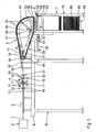
- a system for folding and stacking an endless web of corrugated cardboard 1 is in the Figs. 1 to 3 only indicated schematically.
- the web of corrugated cardboard 1 is conveyed in the system essentially in a conveying direction 2.
- the installation comprises a corrugated cardboard manufacturing device 3.
- Such a corrugated cardboard manufacturing device 3 is used to manufacture the corrugated cardboard web 1 and is, for example, made from FIG DE 103 12 600 A1 , to which reference is hereby made, is known.
- the corrugated cardboard web 1 which can be produced endlessly by means of the corrugated cardboard manufacturing device 3 can have a largely arbitrary number of layers.
- the corrugated cardboard web 1 has a total thickness D.
- the system also comprises a squeezing device 4, a folding device 5, a separating device 6 and a stacking device 7.
- the squeezing device 4 is located downstream of the corrugated cardboard manufacturing device.
- Device 3 arranged, while the folding device 5 is provided downstream of the squeezing device 4.
- the separating device 6 is in turn arranged downstream of the folding device 5.
- the stacking device 7 is located downstream of the separating device 6.
- the squeezing device 4 is arranged on a first platform 8 which is firmly connected to the floor via a first frame 9.
- the stacking device 7 is firmly connected to the floor via a second frame 10.
- the separating device is also on the second frame 10 6 attached.
- the folding device 5 is connected to the first frame 9 and / or the second frame 10 via a third frame 11.
- the frames 9, 10, 11 together form a holding frame for the system.
- the holding frame enables a flexible, modular structure of the system.
- the squeezing device 4 is described in more detail below.
- the squeezing device 4 has an insertion section 12 with a support surface 13. In the area of the insertion section 12, two insertion rollers 14 are arranged.
- the infeed rollers 14 are cylindrical and can each be rotated about an infeed roller axis which is perpendicular or essentially perpendicular to the conveying direction 2.
- the infeed rollers 14 can in particular be drivable in rotation.
- the squeezing device 4 comprises at least one pair of embossing rollers 15, which are each rotatable about an embossing roller axis.
- the embossing rollers 15 can preferably be driven in rotation by means of a drive device not shown in the figures.
- the drive is advantageously clocked intermittently.
- the embossing roller axes are aligned parallel to one another and perpendicular or essentially perpendicular to the conveying direction 2. Like the infeed roller axes, they are arranged vertically one above the other. The distance between the embossing roller axes is adjustable.
- a feed-through gap 16 with a free opening is formed between the surfaces of the embossing rollers 15.
- the free opening of the feed-through gap 16 is at least as large as the thickness D of the corrugated cardboard web 1. It is preferably adapted to the thickness D of the corrugated cardboard web 1 in such a way that the embossing rollers 15 rest against the corrugated cardboard web 1 with a friction fit, but the corrugated cardboard web 1 can pass between the embossing rollers 15 without deformation.
- the two embossing rollers 15 are at least largely identical. They have a circumference in the range from 80 cm to 140 cm.
- the embossing rollers 15 each have at least one embossing element 17 on their surface.
- the embossing element 17 is bar-shaped and blunt. It has an extension in the radial direction of the respective embossing roller 15, that is to say perpendicular to the surface of the corresponding embossing roller 15, which is less than half of the free opening.
- the embossing element 17 is formed continuously. However, it can also be designed in the form of a rake, that is to say interrupted.
- the embossing elements 17 are arranged on the circumference of the embossing rollers 15 in such a way that they meet each other with each revolution of the embossing rollers 15 about the embossing roller axes.
- the embossing elements 17 meet, the free opening of the feed-through gap 16 is reduced to a value which is smaller than the thickness D of the corrugated cardboard web 1.
- the corrugated cardboard web 1 can thus be squeezed by means of the embossing elements 17.
- the embossing elements 17 are currently in the feed-through gap 16. They are there opposite one another.
- the embossing elements 17 are preferably aligned parallel to the embossing roller axes in order to emboss folds 18 in the web of corrugated cardboard 1 which are perpendicular or substantially perpendicular to the conveying direction 2 and thus also perpendicular or substantially perpendicular to it the longitudinal direction of the corrugated cardboard web 1 are oriented.
- the distance between two successive folds 18 corresponds in one embodiment to the circumference of the embossing rollers 15.
- the folds 18 form intended kinks in the web of corrugated cardboard 1, along which it can be folded particularly easily.
- the corrugated cardboard web 1 has a smaller thickness in the region of the folds 18 and thus a lower flexural elasticity than in the region outside the folds 18. It can therefore buckle particularly easily in the region of the folds 18.
- embossing rollers 15 As an alternative to this, it is possible to see only one of the embossing rollers 15 with an embossing element 17.
- the circumference of the embossing roller 15 without the embossing element 17 is not subject to any special requirements. It is largely freely selectable and can, in particular, differ from the circumference of the embossing roller 15 with the embossing element 17.
- embossing rollers 15 are provided, the circumference of which corresponds precisely to an integral multiple of the desired distance between two successive folds 18 in the web of corrugated cardboard 1.
- the embossing rollers 15 of this type have a corresponding number of embossing elements 17 on their surface.
- the embossing elements 17 are evenly distributed over the circumference of the embossing rollers 15, that is to say the angular distance between two respectively adjacent embossing elements 17 is always the same.
- the embossing elements 17 are interchangeable. In this way, the distance between two successive folds 18 in the web of corrugated cardboard 1, which just corresponds to the circumference of the embossing rollers 15, can be set in a simple manner.
- the squeezing device 4 has an outlet section 19 which is provided downstream of the insertion section 12.
- outlet rollers 20 are arranged with outlet roller axes which run parallel to the infeed roller axes.
- the outlet rollers 20 arranged below the corrugated cardboard web 1 can be part of a transport unit 21 which can have supports 22 for storing the outlet rollers 20
- the folding device 5 is arranged downstream of the squeezing device 4, that is to say downstream of it in the conveying direction 2.
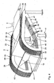
- the folding device 5 comprises a guide device 23 which has an entrance area 24.
- the guide device 23 is in turn formed by two guide units 25, which are of essentially identical design and are arranged perpendicular to the conveying direction 2 next to one another and at a distance from one another.
- Each guide unit 25 is formed by a plurality of rigid frame parts 26 which are firmly connected to one another.
- the frame parts 26 are arranged perpendicular to the conveying direction 2 next to one another and at a distance from one another. They are of essentially identical design and are oriented vertically.
- the frame 11 is fastened to the outer frame parts 26.
- the guide device 23 has a lifting section 27 which adjoins the input area 24 in the conveying direction 2.
- the lifting section 27 is arranged obliquely to a horizontal and thus extends in an inclined plane. It is arranged at an angle ⁇ to the horizontal.
- the angle a is between 2 ° and 20 °, preferably between 5 ° and 15 °. Most preferably, the angle ⁇ is about 10 °.
- the guide device 23 also has a depositing section 28, which adjoins the lifting section 27 in the conveying direction 2.
- the deposit section 28 is arcuate. It is preferably designed as an arc of a circle which extends over an angular range from approximately 90 ° to 130 °, preferably from 100 ° to 120 °, and most preferably encloses an angle of 110 °.
- the deposit section 28 still rises over a small area on the upstream side. In the remaining area of the depositing section 28, the latter slopes down in the conveying direction 2.
- the guide device 23 also has a return section 29, which is connected to the deposit section 28 on the downstream side and to the lifting section 27 on the upstream side.
- the return section 29 extends essentially below the lift section 27 and the deposit section 28. It has a first return area 30 and a second inclined return area 31.
- the return area 30 closes downstream of the deposit -Section 28 and runs essentially horizontally, while the return area 31 extends from the return area 30 obliquely upwards to the horizontal.
- the frame parts 26 of the guide device 23 are designed in accordance with the sections 27, 28, 29. They are each closed on the circumference.
- the frame parts 26 of a guide unit 25 are firmly connected and combined by connecting pieces 32.
- the connecting pieces 32 also ensure that the individual frame parts 26 of a guide unit 25 are arranged at a distance from one another. There is a preferably constant, horizontal distance between these frame parts 26.
- a circulating element 33 which is designed to be closed on the circumference and is guided laterally by the corresponding frame parts 26.
- the circulation elements 33 are thus endless. They are pliable or flexible.
- n frame parts 26 per guide unit 25 n-1 circulating elements 33 are provided per guide unit 25.
- the circulating elements 33 of a guide unit 25 are separated from one another by the frame parts 26.
- five circulating elements 33 are provided per guide unit 25.
- the circulating elements 33 run along the frame parts 26.
- a plurality of guide elements are provided between the individual frame parts 26 of a guide unit 25, which are designed, for example, as rotatable rollers.
- input guide elements 34 are provided in the input area 24 .
- the input guide elements 34 are located between the lifting section 27 and the return section 29.
- the input guide elements 34 of a guide unit 25 have a common input guide element axis which is perpendicular to the conveyor -Direction 2 is oriented.
- In the depositing section 28 there is a multiplicity of depositing guide elements 35 which sit on different depositing guide element axes oriented perpendicular to the conveying direction 2.
- the deflecting elements 36 of a guide unit 25 sit on a deflecting element axis perpendicular to the conveying direction 2 and are preferably rotatable independently of one another.
- Further guide elements 37 are located between the return area 30 and the return area 31.
- the guide elements 37 of a guide unit 25 sit on a common guide element axis perpendicular to the conveying direction 2 and are preferred can be rotated independently of each other.
- the circulating elements 33 are each guided on the outside around the guide elements 34, 35, 36, 37 which determine the path of the circulating elements 33.
- a plurality of engagement elements are attached to the circulating elements 33.
- the number of engagement elements depends on the number of circulation elements 33. It corresponds to the number of circulating elements 33 per guide unit 25. With n circulating elements 33 per guide unit 25, n engagement elements are provided. A total of five engagement elements are provided here.
- the engagement elements are each elongated. They extend perpendicular to the conveying direction 2 and run essentially parallel to one another.
- the engagement elements are each fastened with their mutually opposite longitudinal ends 43 to the circulating elements 33, which form a circulating element pair.
- the guide elements 33 which are guided in the two guide units 25 between corresponding frame parts 26, each form a pair of circulating elements.
- the first engagement element 38 is attached to the two innermost circumferential elements 33 of the guide units 25. These two circumferential elements 33 run adjacent to the two innermost frame parts 26 of the guide units 25.
- the innermost frame parts 26 face one another.
- the engagement element 39 is attached to the two circulating elements 33 of the guide units 25, which run adjacent to the innermost circulating elements 33 of the guide units 25.
- the engagement element 40 is firmly connected to the central circulation elements 33 of the guide units 25.
- the engaging member 42 is fixed to the outermost circulating members 33 of the guide units 25.
- the outermost circumferential elements 33 run adjacent to the outermost frame parts 26 of the guide units 25.
- the outermost frame parts 26 face away from one another.
- the engagement element 41 is connected to the circulating elements 33, which are arranged between the outermost circulating elements 33 and the central circulating elements 33 of the guide units 25.
- the two innermost circumferential elements 33 are at a smaller distance from one another than the two outermost circumferential elements 33.
- the circumferential elements 33 which belong together in pairs, are each coupled to one another via the engagement elements 38 to 42.
- a drive device 44 for rotationally driving the same is assigned to the input guide elements 34.
- the drive device 44 comprises a plurality of drive belts 45 which synchronously drive the circulating elements 33 which belong together in pairs.
- separate drive devices 44 can also be provided.
- the rotating element pairs can be driven or moved independently of one another.
- the folding device 5 further comprises an elongated, rigid depositing support element 46, which is arranged between the guide units 25.
- the depositing support element 46 extends between the two innermost frame parts 26. The longitudinal ends of the depositing support element 46 are provided adjacent to the transition point between the return areas 30, 31 of the guide units 25 .
- the depositing support element 46 is formed in a star shape. It comprises three depositing support arms 47, which run away from one another radially from a common center. A different number of deposit support arms 47 is also possible. For example, two, four or five lay-down support arms 47 can be used.
- the deposit support arms 47 each have an identical angular spacing from one another.
- the depositing support element 46 can be driven in rotation by a corresponding drive and extends perpendicular to the conveying direction 2.
- the stacking device 7 is located essentially below the return area 30.
- the separating device 6 is attached to the frame 10 of the stacking device 7 at the top. It comprises a cutting knife 48, which is designed as a circular knife and can be driven in rotation via a cutting knife drive 49.
- the cutting knife drive 49 can be displaced perpendicular to the conveying direction 2.
- corresponding guide rails 50 are provided on the frame 10, which extend horizontally perpendicular to the conveying direction 2 at the top of the frame 10.
- a hydraulic element or an electric drive can be used to move the cutting blade drive 49.
- the separating device 6 further comprises a separating table 51 which is designed as a counter element and which is also provided at the top of the frame 10.
- the cutting table 51 comprises a penetration recess 52 on the front side, which extends over the entire width of the cutting table 51 and is open towards the cutting knife 48.
- the separating table 51 can be horizontally displaced in its position.
- the separating table 51 is assigned a separating table drive 53 which can move the separating table 51 between a separating position and a non-separating position. In the separating position, the separating knife 48 protrudes into the penetration recess 52. In the non-separating position, the separating knife 48 and the penetrating recess 52 are spaced from one another.
- the stacking device 7 further comprises a stacking table 54, which is mounted in the frame 10 in a height-adjustable manner.
- the stacking table 54 has an upper support surface 55.
- a corrugated cardboard web 1 is made of, for example, the DE 103 12 600 A1 known processes.
- one or more cover sheets with one or more corrugated sheets are connected to one another in a method known to the person skilled in the art to form the sheet of corrugated cardboard 1 DE 43 05 158 A1 is referred.
- the endless web of corrugated cardboard 1 coming from the corrugated cardboard manufacturing device 3 is then provided with impressions in the squeezing device 4.
- the corrugated cardboard web 1 is passed between the embossing rollers 15.
- the two embossing elements 17 meet, so that in the area of the corrugated cardboard web located between the embossing elements 17 1 a fold 18 is embossed.
- the drive of the embossing rollers 15 and / or the arrangement of the embossing elements 17 on these are precisely matched to one another for this purpose.
- the embossing elements 17 can be designed in such a way that they form corresponding perforations in the web 1 of corrugated cardboard. Even after the corrugated cardboard web 1 has passed through the squeezing device 4, the corrugated cardboard web 1 is formed contiguously in the conveying direction 2.
- the corrugated cardboard web 1 has a multiplicity of folds 18 which are spaced apart from one another are.
- the folds 18 are arranged parallel to one another and run perpendicular or essentially perpendicular to the conveying direction 2.
- the folded corrugated cardboard web 1 is transported on to the folding device 5 in the conveying direction 2.
- a deflection table 56 can be arranged in front of the folding device 5, the table surface 57 of which rises in the conveying direction 2.
- the web of corrugated cardboard 1 is thus deflected upwards or vertically from its original horizontal extent by the table surface 57.
- the web of corrugated cardboard 1 slides on top of the table surface 57.
- the web of corrugated cardboard 1 then arrives at the folding device 5.
- the circulation elements 33 are continuously driven by the input guide elements 34 which are driven in rotation. They are driven in such a way that they have a common direction of rotation.
- the direction of circulation of the circulation elements 33 essentially corresponds to the conveying direction 2 in the area of the lifting section 27. In the area of the return section 29, however, the direction of rotation of the circulating elements 33 is essentially in the opposite direction to the conveying direction 2.
- the engaging elements 38 to 42 attached to the circulating elements 33 are guided accordingly.
- the circulating elements 33 can be accelerated or decelerated with respect to one another at any time in order to be able to influence the folding progress of the corrugated cardboard web 1. A relative movement then occurs between these accelerated or decelerated rotating elements 33.
- the web of corrugated cardboard 1 enters the guide device 23 via the entrance area 24.
- the circulation elements 33 are driven by the drive device 44 or the input guide elements 34 in such a way that in each case one engagement element 38 to 42 in the lifting area 27 from below onto every second fold 18 in the conveying direction 2 meets.
- the engagement elements 38 to 42 thus come into engagement with the corrugated cardboard web 1 from below in the lifting region 27.
- the web of corrugated cardboard 1 is guided in some areas by the engagement elements 38 to 42 between the guide units 25, which for this purpose have a corresponding spacing from one another. It is carried along by the engagement elements 38 to 42.
- the corrugated cardboard sheet 1 is further raised along the raising portion 27 by the engaging members 38 to 42.
- the circulating members 33 and the engaging members 38 to 42 gain height in the lifting portion 27. The same applies to the corrugated cardboard web 1, which runs in the lifting section 27 at an angle to the horizontal.
- the corrugated cardboard web 1 is also raised further by the engagement elements 38 to 42 in an area of the deposit section 28 on the inlet side.
- the circulation elements 33 run accordingly.
- the engagement elements 38 to 42 have their maximum height.
- the areas of the corrugated cardboard web 1 adjacent to a fold 18 located there are oriented essentially vertically.
- the corrugated cardboard web 1 After an apex of the guide device 23, the corrugated cardboard web 1 is, as it were, folded over or folded over in the depositing section 28.
- the circulating elements 33 then lose height in the depositing section 28.
- the circumferential elements 33 and the engagement elements 38 to 42 describe an arcuate path there.
- the areas of the corrugated cardboard web 1 that are adjacent to the respective fold 18 come closer to one another.
- the areas adjacent to the respective fold 18 essentially rest against one another and run horizontally.
- the corrugated cardboard web 1 has a height position which is smaller than the height position of the corrugated cardboard web 1 in the squeezing device 4.
- the engagement elements 38 to 42 then come after the deposit section 28 in the return area 30 out of engagement with the folded corrugated cardboard web 1. They are then guided back to the lifting section 27 via the return section 29, so that a continuous Circulation of the engagement elements 38 to 42 is guaranteed.
- the depositing support element 46 gives the corrugated cardboard web 1 an exact fold-over point in the area of the free folds 18. There the folding over of the corrugated cardboard web 1 is supported by the depositing support arms 47.
- the depositing support element 46 partially supports the free folds 18. The free folds 18 are also guided in the direction of the depositing section 28.
- the stack 58 rests there on the support surface 55 of the stacking table 54. As the height of the stack 58 increases, the stacking table 54 is moved downwards.
- the folded corrugated cardboard web 1 can be cut or separated transversely to the conveying direction 2 by the cutting device 6.
- the separating knife 48 is to be set in rotation via the separating knife drive 49 and introduced into the web of corrugated cardboard 1.
- the separating table 51 must be moved from its non-separating position into its separating position, so that the rotating separating knife 48 penetrates through the corrugated cardboard web 1 into the penetration recess 52 of the separating table 51 can and thus forms a counter-element for the cutting knife 48.
- the separating knife 48 is then to be moved along a fold 18 over the entire width of the corrugated cardboard web 1.
- the distance between the engagement elements 38 to 42 must also be adjusted. To do this, the pairs of circulating elements must be controlled individually. Relative movements then occur between the pairs of rotating elements during the format change.
- the format change can take place while the system is running.
- the folding device 5 can be adjusted by machine to the changed spacing of the folds 18.
- the engagement elements 38 to 42 are always adjusted at a distance from one another in order to be able to continuously influence the folding process over their circulation path.
- this adjustment takes place in a more extreme manner, that is, the distance between the engagement elements 38 to 42 is adapted on the one hand to the new format, and on the other hand the distance is adapted to the respective folding progress, what is dependent on the position of the engagement element 38 to 42 on its orbit.
Landscapes
- Engineering & Computer Science (AREA)
- Mechanical Engineering (AREA)
- Making Paper Articles (AREA)
- Folding Of Thin Sheet-Like Materials, Special Discharging Devices, And Others (AREA)
Claims (15)
- Installation de pliage et d'empilement d'une bande de carton ondulé (1) sans fin comprenanta) au moins un dispositif de fabrication de carton ondulé (3) pour la fabrication d'une bande de carton ondulé (1) sans fin,b) un dispositif d'écrasement (4) disposé en aval d'au moins un dispositif de fabrication de carton ondulé (3) pour marquer des pliures (18) dans la bande de carton ondulé (1),c) un dispositif de pliage (5) disposé en aval d'au moins un dispositif d'écrasement (4) pour le pliage de la bande de carton ondulé (1) le long de la pliure (18), le dispositif de pliage (5) présentant un premier élément d'encliquetage (38), commandé dans son déplacement, pour l'entraînement de la bande de carton ondulé (1) dans la zone d'une première pliure (18), etd) un dispositif d'empilement (7) disposé en aval du dispositif de pliage (5) pour l'empilement en piles (58) de la bande de carton ondulé (1) le long de la pliure (18),
caractérisée en ce que le dispositif de pliage (5) en outre présentef) au moins un second élément d'encliquetage (39 à 42), indépendant du premier élément d'encliquetage (38), commandé dans son déplacement, pour l'entraînement de la bande de carton ondulé (1) dans la zone d'une seconde pliure (18) disposée en amont par rapport à la première pliure (18), les éléments d'encliquetage (38 à 42) pouvant être accélérés et/ou décélérés individuellement. - Installation selon le revendication 1 caractérisée en ce que le dispositif de pliage (5) présente un dispositif de commande (23) pour le guidage des éléments d'encliquetage (38 à 42), le dispositif de commande (23) établissant par avance une bande de déplacement, de préférence une bande de déplacement fermée pour les éléments d'encliquetage (38 à 42).
- Installation selon la revendication 2 caractérisée en ce que le dispositif de commande (23) guide au moins un premier élément de rotation (33), ayant un parcours circulaire, pouvant être entraîné, auquel l'élément d'encliquetage (38) est fixé.
- Installation selon les revendications 2 ou 3 caractérisée en ce que le dispositif de commande (23) guide au moins un deuxième élément de rotation (33), ayant un parcours circulaire, auquel est fixé l'au moins deuxième élément d'encliquetage (39 à 42).
- Installation selon les revendications 3 et 4 caractérisée en ce que les éléments de rotation (33) sont disposés les uns à côté des autres dans le dispositif de commande (23).
- Installation selon la revendication 3 et 4 ou selon la revendication 5, caractérisée en ce que le premier élément de rotation (33) et au moins le deuxième élément de rotation (33) peuvent être entraînés indépendamment l'un de l'autre.
- Installation selon l'une des revendications de 3 à 6 caractérisée en ce que le dispositif de commande (23) présente au moins une partie en relèvement (27), de pente ascendante, dans laquelle les éléments de rotation (33) sont guidés pour soulever la bande de carton ondulé (1) vers le haut.
- Installation selon la revendication 7 caractérisée en ce que le dispositif de commande (23), en aval de la partie en relèvement (27), présente au moins une partie de dépose en pente descendante (28), dans laquelle les éléments de rotation (33) sont menés dans une descente pour un dépôt à l'état plié de la bande de carton ondulé (1), où au moins une partie de dépose (28) s'étend en forme d'une courbe.
- Installation selon la revendication 8 caractérisée en ce que le dispositif de guidage (23) présente une partie d'un circuit retour (29), en aval de la partie de dépose (28), qui s'enchaîne avec la partie en relèvement (27), pour renvoyer les éléments d'encliquetage (38 à 42) du côté de l'entrée.
- Installation selon l'une des revendications précédentes caractérisée en ce que le dispositif de pliage (5) présente au moins un élément de support de dépose (46), pouvant être entraîné en rotation, pour supporter la bande de carton ondulé pliée, l'élément de support de dépose (46) présentant au moins deux bras supports de dépose (47) pour une action réciproque avec des domaines de bord de pliage non effectué de la bande de carton ondulé (1) et de préférence est conçu en forme d'étoile.
- Installation selon l'une des revendications précédentes caractérisée en ce que le dispositif d'empilement (7) présente une table d'empilement (54) pouvant être réglée en hauteur pour porter l'empilement (58).
- Installation selon l'une des revendications précédentes caractérisée par un dispositif de séparation (6) pour séparer la bande de carton ondulé (1), le dispositif de séparation (6) étant disposé entre le dispositif de pliage (5) et le dispositif d'empilement (7).
- Installation selon la revendication 12 caractérisée en ce que le dispositif de séparation (6) présente au moins un couteau de séparation (48) et au moins un contre-élément (51) pour agir conjointement avec au moins un couteau de séparation (48), au moins un évidement de rentrée (52) étant de préférence formé dans au moins un contre-élément (51) pour la réception au moins partielle d'au moins un couteau de séparation (48).
- Installation selon la revendication 13 caractérisée en ce que le couteau de séparation (48) et le contre-élément (51) peuvent être déplacés l'un sur l'autre pour la séparation de la bande de carton ondulé (1).
- Procédé pour le pliage et l'empilement d'une bande de carton ondulé sans fin (1) comprenant les étapes suivantes :- fabrication d'une bande de carton ondulé sans fin (1),- marquage de pliures (18) dans la bande de carton ondulé (1),- pliage de la bande de carton ondulé (1) le long de la pliure (18) avec un premier élément d'encliquetage (38), commandé dans son déplacement, qui entraîne la bande de carton ondulé (1) dans la zone d'une première pliure (18), et- empilement en piles (58) de la bande de carton ondulé (1),caractérisé par
un pliage en outre-- comprenant un premier élément d'encliquetage (38), commandé dans son déplacement, qui entraîne la bande de carton ondulé (1) dans la zone d'une première pliure (18), et-- comprenant au moins un deuxième élément d'encliquetage (39 à 42), commandé dans son déplacement, indépendant du premier élément d'encliquetage (38), qui entraîne la bande de carton ondulé (1) dans la zone d'une seconde pliure (18) disposée en amont de la première pliure (18), les éléments d'encliquetage (38 à 42) pouvant être accélérés et/ou décélérés individuellement.
Applications Claiming Priority (1)
| Application Number | Priority Date | Filing Date | Title |
|---|---|---|---|
| DE102010031668A DE102010031668B4 (de) | 2010-07-22 | 2010-07-22 | Falt - Anlage für Wellpappebahnen |
Publications (3)
| Publication Number | Publication Date |
|---|---|
| EP2409939A1 EP2409939A1 (fr) | 2012-01-25 |
| EP2409939B1 EP2409939B1 (fr) | 2012-12-05 |
| EP2409939B2 true EP2409939B2 (fr) | 2021-04-21 |
Family
ID=44802541
Family Applications (1)
| Application Number | Title | Priority Date | Filing Date |
|---|---|---|---|
| EP11174201.1A Active EP2409939B2 (fr) | 2010-07-22 | 2011-07-15 | Installation de pliage et d'agrafage pour bandes de carton ondulé |
Country Status (4)
| Country | Link |
|---|---|
| US (1) | US9216877B2 (fr) |
| EP (1) | EP2409939B2 (fr) |
| DE (1) | DE102010031668B4 (fr) |
| ES (1) | ES2399615T5 (fr) |
Families Citing this family (5)
| Publication number | Priority date | Publication date | Assignee | Title |
|---|---|---|---|---|
| ITUD20120036A1 (it) * | 2012-03-06 | 2013-09-07 | Panotec Srl | Macchina automatizzata per piegare a zig-zag ed impilare un nastro cordonato di materiale sufficientemente rigido |
| CN112707227B (zh) * | 2021-01-08 | 2024-05-10 | 浙江新元创自动化设备股份有限公司 | 一种折纸机 |
| IT202100012926A1 (it) * | 2021-05-19 | 2022-11-19 | Int Boxes Srl | Un sistema per formare e piegare a ventaglio un materiale laminare nonche' suo metodo d'uso |
| EP4341189B1 (fr) * | 2021-05-19 | 2025-08-06 | Panotec SRL | Système et procédé d'empilement d'une bande continue pliée en accordéon de matériau en feuille |
| DE102023211342A1 (de) | 2023-11-15 | 2025-05-15 | Universal Corrugated B.V. | Verfahren zum Stapeln von Wellpappe, Bogen- und Faltstapeleinheit, Wellpappenanlage und Verfahren zum Umrüsten einer Bogenstapeleinheit |
Family Cites Families (9)
| Publication number | Priority date | Publication date | Assignee | Title |
|---|---|---|---|---|
| US2604984A (en) | 1949-03-18 | 1952-07-29 | Seaboard Container Corp | Fan-folded stack of corrugated board for tubular containers |
| US4210318A (en) * | 1978-05-24 | 1980-07-01 | Ga-Vehren Engineering Company | Fan folding and stacking device |
| US5058872A (en) | 1989-08-08 | 1991-10-22 | Didde Web Press Corp. | Chain cam |
| DE4305158C3 (de) | 1993-02-19 | 2003-10-30 | Bhs Corr Masch & Anlagenbau | Wellpappenmaschine zur Herstellung einseitiger Wellpappe |
| US6071223A (en) * | 1997-11-13 | 2000-06-06 | Pentax Technologies Corporation | System for directing a leading edge of continuous form paper onto a stack |
| US7008364B2 (en) * | 2002-09-27 | 2006-03-07 | C.G. Bretting Manufacturing Company, Inc. | Sheet folding apparatus and method |
| DE10306212A1 (de) | 2003-02-13 | 2004-08-26 | Hermann Hötten Maschinenbau GmbH | Verfahren und Vorrichtung zur Leporellofaltung von Endlosbahnen |
| DE10312600A1 (de) | 2003-03-21 | 2004-10-07 | Bhs Corrugated Maschinen- Und Anlagenbau Gmbh | Wellpappe-Anlage sowie Verfahren zur Herstellung von Wellpappe-Bögen |
| DE102008025888A1 (de) * | 2008-05-29 | 2009-12-24 | Bhs Corrugated Maschinen- Und Anlagenbau Gmbh | Falteinrichtung |
-
2010
- 2010-07-22 DE DE102010031668A patent/DE102010031668B4/de active Active
-
2011
- 2011-07-14 US US13/182,793 patent/US9216877B2/en active Active
- 2011-07-15 EP EP11174201.1A patent/EP2409939B2/fr active Active
- 2011-07-15 ES ES11174201T patent/ES2399615T5/es active Active
Also Published As
| Publication number | Publication date |
|---|---|
| ES2399615T3 (es) | 2013-04-02 |
| US9216877B2 (en) | 2015-12-22 |
| EP2409939B1 (fr) | 2012-12-05 |
| EP2409939A1 (fr) | 2012-01-25 |
| DE102010031668A1 (de) | 2012-01-26 |
| ES2399615T5 (es) | 2021-11-08 |
| US20120021886A1 (en) | 2012-01-26 |
| DE102010031668B4 (de) | 2012-08-02 |
Similar Documents
| Publication | Publication Date | Title |
|---|---|---|
| DE3881008T2 (de) | Verfahren zur Bildung von Zickzackstapeln, ausgehend von einer Endlosbahn aus biegsamem Material und Maschine zur Durchführung dieses Verfahrens. | |
| EP0189090B1 (fr) | Dispositif de pliage de bandes | |
| DE3885183T2 (de) | Vorrichtung zum Falten und Aufstapeln von Servietten, ausgehend von einer endlosen Bahn aus Papier oder einem anderen Material. | |
| DE1461953C3 (de) | Vorrichtung zum Anbringen von flachen Beutelverschlussen | |
| EP2199240B1 (fr) | Dispositif destiné à la séparation de pièces | |
| DE3008842C2 (fr) | ||
| DE1802760B2 (de) | Stapelvorrichtung für Druckerzeugnisse, insbesondere Zeitungen | |
| EP0243799B1 (fr) | Dispositif de pliage de bandes | |
| EP2409939B1 (fr) | Installation de pliage et d'agrafage pour bandes de carton ondulé | |
| EP0366038A2 (fr) | Dispositif pour plier en zigzag et empiler une bande de matériau | |
| DE2245515C3 (de) | Stapelvorrichtung zum Aufsetzen und Austragen von Tütenstapeln | |
| DE3020009A1 (de) | Vorrichtung fuer die herstellung von beuteln aus einer kunststoffolien-schlauchbahn | |
| DE19612239C2 (de) | Vorrichtung zur Herstellung eines randbereichsprofilierten Bleches, insbesondere aus einem ebenen Blech | |
| EP2128069B1 (fr) | Dispositif de pliage | |
| EP2048094A2 (fr) | Dispositif de transport de bandes de carton ondulé | |
| DE2206137B2 (de) | Fördereinrichtung für das Zuführen von Stückwaren zu einer Zähl- und/ oder Verpackungsstation | |
| DE2329850A1 (de) | Vorrichtung zum wenden und stapeln von gittermatten | |
| CH668216A5 (en) | Printed item-trimming machine - has compartments and knives on parallel endless chains travelling at same speed | |
| DE3700930C2 (fr) | ||
| DE2732837A1 (de) | Einrichtung zum stapeln von blattfoermigen gegenstaenden | |
| EP3046842B1 (fr) | Dispositif de fabrication d'unités d'emballage | |
| DE602004004205T2 (de) | Automatisches System zum Sortieren und Palettieren von Artikeln | |
| DE69719447T2 (de) | Vorrichtung zum Zuführen und Schneiden von Folien in einer Verpackungsmaschine | |
| DE3143826C2 (de) | Einrichtung zum fortsetzbaren Falzen eines einzelnen Papierbogens | |
| EP2316767B1 (fr) | Dispositif et procédé de fabrication de piles de produits d'impression |
Legal Events
| Date | Code | Title | Description |
|---|---|---|---|
| AK | Designated contracting states |
Kind code of ref document: A1 Designated state(s): AL AT BE BG CH CY CZ DE DK EE ES FI FR GB GR HR HU IE IS IT LI LT LU LV MC MK MT NL NO PL PT RO RS SE SI SK SM TR |
|
| AX | Request for extension of the european patent |
Extension state: BA ME |
|
| PUAI | Public reference made under article 153(3) epc to a published international application that has entered the european phase |
Free format text: ORIGINAL CODE: 0009012 |
|
| 17P | Request for examination filed |
Effective date: 20120128 |
|
| GRAP | Despatch of communication of intention to grant a patent |
Free format text: ORIGINAL CODE: EPIDOSNIGR1 |
|
| GRAS | Grant fee paid |
Free format text: ORIGINAL CODE: EPIDOSNIGR3 |
|
| GRAA | (expected) grant |
Free format text: ORIGINAL CODE: 0009210 |
|
| AK | Designated contracting states |
Kind code of ref document: B1 Designated state(s): AL AT BE BG CH CY CZ DE DK EE ES FI FR GB GR HR HU IE IS IT LI LT LU LV MC MK MT NL NO PL PT RO RS SE SI SK SM TR |
|
| REG | Reference to a national code |
Ref country code: GB Ref legal event code: FG4D Free format text: NOT ENGLISH |
|
| REG | Reference to a national code |
Ref country code: CH Ref legal event code: EP |
|
| REG | Reference to a national code |
Ref country code: AT Ref legal event code: REF Ref document number: 587170 Country of ref document: AT Kind code of ref document: T Effective date: 20121215 |
|
| REG | Reference to a national code |
Ref country code: IE Ref legal event code: FG4D Free format text: LANGUAGE OF EP DOCUMENT: GERMAN |
|
| REG | Reference to a national code |
Ref country code: DE Ref legal event code: R096 Ref document number: 502011000256 Country of ref document: DE Effective date: 20130131 |
|
| REG | Reference to a national code |
Ref country code: ES Ref legal event code: FG2A Ref document number: 2399615 Country of ref document: ES Kind code of ref document: T3 Effective date: 20130402 |
|
| PG25 | Lapsed in a contracting state [announced via postgrant information from national office to epo] |
Ref country code: FI Free format text: LAPSE BECAUSE OF FAILURE TO SUBMIT A TRANSLATION OF THE DESCRIPTION OR TO PAY THE FEE WITHIN THE PRESCRIBED TIME-LIMIT Effective date: 20121205 Ref country code: NO Free format text: LAPSE BECAUSE OF FAILURE TO SUBMIT A TRANSLATION OF THE DESCRIPTION OR TO PAY THE FEE WITHIN THE PRESCRIBED TIME-LIMIT Effective date: 20130305 Ref country code: SE Free format text: LAPSE BECAUSE OF FAILURE TO SUBMIT A TRANSLATION OF THE DESCRIPTION OR TO PAY THE FEE WITHIN THE PRESCRIBED TIME-LIMIT Effective date: 20121205 Ref country code: HR Free format text: LAPSE BECAUSE OF FAILURE TO SUBMIT A TRANSLATION OF THE DESCRIPTION OR TO PAY THE FEE WITHIN THE PRESCRIBED TIME-LIMIT Effective date: 20121205 Ref country code: LT Free format text: LAPSE BECAUSE OF FAILURE TO SUBMIT A TRANSLATION OF THE DESCRIPTION OR TO PAY THE FEE WITHIN THE PRESCRIBED TIME-LIMIT Effective date: 20121205 |
|
| REG | Reference to a national code |
Ref country code: NL Ref legal event code: VDEP Effective date: 20121205 |
|
| REG | Reference to a national code |
Ref country code: LT Ref legal event code: MG4D |
|
| PG25 | Lapsed in a contracting state [announced via postgrant information from national office to epo] |
Ref country code: PL Free format text: LAPSE BECAUSE OF FAILURE TO SUBMIT A TRANSLATION OF THE DESCRIPTION OR TO PAY THE FEE WITHIN THE PRESCRIBED TIME-LIMIT Effective date: 20121205 Ref country code: SI Free format text: LAPSE BECAUSE OF FAILURE TO SUBMIT A TRANSLATION OF THE DESCRIPTION OR TO PAY THE FEE WITHIN THE PRESCRIBED TIME-LIMIT Effective date: 20121205 Ref country code: GR Free format text: LAPSE BECAUSE OF FAILURE TO SUBMIT A TRANSLATION OF THE DESCRIPTION OR TO PAY THE FEE WITHIN THE PRESCRIBED TIME-LIMIT Effective date: 20130306 Ref country code: LV Free format text: LAPSE BECAUSE OF FAILURE TO SUBMIT A TRANSLATION OF THE DESCRIPTION OR TO PAY THE FEE WITHIN THE PRESCRIBED TIME-LIMIT Effective date: 20121205 |
|
| PG25 | Lapsed in a contracting state [announced via postgrant information from national office to epo] |
Ref country code: CZ Free format text: LAPSE BECAUSE OF FAILURE TO SUBMIT A TRANSLATION OF THE DESCRIPTION OR TO PAY THE FEE WITHIN THE PRESCRIBED TIME-LIMIT Effective date: 20121205 Ref country code: RS Free format text: LAPSE BECAUSE OF FAILURE TO SUBMIT A TRANSLATION OF THE DESCRIPTION OR TO PAY THE FEE WITHIN THE PRESCRIBED TIME-LIMIT Effective date: 20121205 Ref country code: EE Free format text: LAPSE BECAUSE OF FAILURE TO SUBMIT A TRANSLATION OF THE DESCRIPTION OR TO PAY THE FEE WITHIN THE PRESCRIBED TIME-LIMIT Effective date: 20121205 Ref country code: IS Free format text: LAPSE BECAUSE OF FAILURE TO SUBMIT A TRANSLATION OF THE DESCRIPTION OR TO PAY THE FEE WITHIN THE PRESCRIBED TIME-LIMIT Effective date: 20130405 Ref country code: BG Free format text: LAPSE BECAUSE OF FAILURE TO SUBMIT A TRANSLATION OF THE DESCRIPTION OR TO PAY THE FEE WITHIN THE PRESCRIBED TIME-LIMIT Effective date: 20130305 Ref country code: SK Free format text: LAPSE BECAUSE OF FAILURE TO SUBMIT A TRANSLATION OF THE DESCRIPTION OR TO PAY THE FEE WITHIN THE PRESCRIBED TIME-LIMIT Effective date: 20121205 |
|
| PG25 | Lapsed in a contracting state [announced via postgrant information from national office to epo] |
Ref country code: RO Free format text: LAPSE BECAUSE OF FAILURE TO SUBMIT A TRANSLATION OF THE DESCRIPTION OR TO PAY THE FEE WITHIN THE PRESCRIBED TIME-LIMIT Effective date: 20121205 Ref country code: PT Free format text: LAPSE BECAUSE OF FAILURE TO SUBMIT A TRANSLATION OF THE DESCRIPTION OR TO PAY THE FEE WITHIN THE PRESCRIBED TIME-LIMIT Effective date: 20130405 Ref country code: NL Free format text: LAPSE BECAUSE OF FAILURE TO SUBMIT A TRANSLATION OF THE DESCRIPTION OR TO PAY THE FEE WITHIN THE PRESCRIBED TIME-LIMIT Effective date: 20121205 |
|
| PLBI | Opposition filed |
Free format text: ORIGINAL CODE: 0009260 |
|
| 26 | Opposition filed |
Opponent name: MINDA INDUSTRIEANLAGEN GMBH Effective date: 20130904 |
|
| PLAX | Notice of opposition and request to file observation + time limit sent |
Free format text: ORIGINAL CODE: EPIDOSNOBS2 |
|
| PG25 | Lapsed in a contracting state [announced via postgrant information from national office to epo] |
Ref country code: DK Free format text: LAPSE BECAUSE OF FAILURE TO SUBMIT A TRANSLATION OF THE DESCRIPTION OR TO PAY THE FEE WITHIN THE PRESCRIBED TIME-LIMIT Effective date: 20121205 |
|
| REG | Reference to a national code |
Ref country code: DE Ref legal event code: R026 Ref document number: 502011000256 Country of ref document: DE Effective date: 20130904 |
|
| PG25 | Lapsed in a contracting state [announced via postgrant information from national office to epo] |
Ref country code: CY Free format text: LAPSE BECAUSE OF FAILURE TO SUBMIT A TRANSLATION OF THE DESCRIPTION OR TO PAY THE FEE WITHIN THE PRESCRIBED TIME-LIMIT Effective date: 20121205 |
|
| BERE | Be: lapsed |
Owner name: BHS CORRUGATED MASCHINEN-UND ANLAGENBAU G.M.B.H. Effective date: 20130731 |
|
| PLBB | Reply of patent proprietor to notice(s) of opposition received |
Free format text: ORIGINAL CODE: EPIDOSNOBS3 |
|
| PG25 | Lapsed in a contracting state [announced via postgrant information from national office to epo] |
Ref country code: MC Free format text: LAPSE BECAUSE OF FAILURE TO SUBMIT A TRANSLATION OF THE DESCRIPTION OR TO PAY THE FEE WITHIN THE PRESCRIBED TIME-LIMIT Effective date: 20121205 |
|
| REG | Reference to a national code |
Ref country code: IE Ref legal event code: MM4A |
|
| PG25 | Lapsed in a contracting state [announced via postgrant information from national office to epo] |
Ref country code: BE Free format text: LAPSE BECAUSE OF NON-PAYMENT OF DUE FEES Effective date: 20130731 |
|
| PG25 | Lapsed in a contracting state [announced via postgrant information from national office to epo] |
Ref country code: IE Free format text: LAPSE BECAUSE OF NON-PAYMENT OF DUE FEES Effective date: 20130715 |
|
| REG | Reference to a national code |
Ref country code: CH Ref legal event code: PL |
|
| PG25 | Lapsed in a contracting state [announced via postgrant information from national office to epo] |
Ref country code: CH Free format text: LAPSE BECAUSE OF NON-PAYMENT OF DUE FEES Effective date: 20140731 Ref country code: LI Free format text: LAPSE BECAUSE OF NON-PAYMENT OF DUE FEES Effective date: 20140731 |
|
| PG25 | Lapsed in a contracting state [announced via postgrant information from national office to epo] |
Ref country code: SM Free format text: LAPSE BECAUSE OF FAILURE TO SUBMIT A TRANSLATION OF THE DESCRIPTION OR TO PAY THE FEE WITHIN THE PRESCRIBED TIME-LIMIT Effective date: 20121205 |
|
| APBM | Appeal reference recorded |
Free format text: ORIGINAL CODE: EPIDOSNREFNO |
|
| APBP | Date of receipt of notice of appeal recorded |
Free format text: ORIGINAL CODE: EPIDOSNNOA2O |
|
| PG25 | Lapsed in a contracting state [announced via postgrant information from national office to epo] |
Ref country code: MT Free format text: LAPSE BECAUSE OF FAILURE TO SUBMIT A TRANSLATION OF THE DESCRIPTION OR TO PAY THE FEE WITHIN THE PRESCRIBED TIME-LIMIT Effective date: 20121205 Ref country code: TR Free format text: LAPSE BECAUSE OF FAILURE TO SUBMIT A TRANSLATION OF THE DESCRIPTION OR TO PAY THE FEE WITHIN THE PRESCRIBED TIME-LIMIT Effective date: 20121205 |
|
| APAH | Appeal reference modified |
Free format text: ORIGINAL CODE: EPIDOSCREFNO |
|
| PG25 | Lapsed in a contracting state [announced via postgrant information from national office to epo] |
Ref country code: LU Free format text: LAPSE BECAUSE OF NON-PAYMENT OF DUE FEES Effective date: 20130715 Ref country code: MK Free format text: LAPSE BECAUSE OF FAILURE TO SUBMIT A TRANSLATION OF THE DESCRIPTION OR TO PAY THE FEE WITHIN THE PRESCRIBED TIME-LIMIT Effective date: 20121205 Ref country code: HU Free format text: LAPSE BECAUSE OF FAILURE TO SUBMIT A TRANSLATION OF THE DESCRIPTION OR TO PAY THE FEE WITHIN THE PRESCRIBED TIME-LIMIT; INVALID AB INITIO Effective date: 20110715 |
|
| APBQ | Date of receipt of statement of grounds of appeal recorded |
Free format text: ORIGINAL CODE: EPIDOSNNOA3O |
|
| REG | Reference to a national code |
Ref country code: FR Ref legal event code: PLFP Year of fee payment: 6 |
|
| REG | Reference to a national code |
Ref country code: FR Ref legal event code: PLFP Year of fee payment: 7 |
|
| REG | Reference to a national code |
Ref country code: AT Ref legal event code: MM01 Ref document number: 587170 Country of ref document: AT Kind code of ref document: T Effective date: 20160715 |
|
| PG25 | Lapsed in a contracting state [announced via postgrant information from national office to epo] |
Ref country code: AT Free format text: LAPSE BECAUSE OF NON-PAYMENT OF DUE FEES Effective date: 20160715 |
|
| REG | Reference to a national code |
Ref country code: FR Ref legal event code: PLFP Year of fee payment: 8 |
|
| PG25 | Lapsed in a contracting state [announced via postgrant information from national office to epo] |
Ref country code: AL Free format text: LAPSE BECAUSE OF FAILURE TO SUBMIT A TRANSLATION OF THE DESCRIPTION OR TO PAY THE FEE WITHIN THE PRESCRIBED TIME-LIMIT Effective date: 20121205 |
|
| APBU | Appeal procedure closed |
Free format text: ORIGINAL CODE: EPIDOSNNOA9O |
|
| PUAH | Patent maintained in amended form |
Free format text: ORIGINAL CODE: 0009272 |
|
| STAA | Information on the status of an ep patent application or granted ep patent |
Free format text: STATUS: PATENT MAINTAINED AS AMENDED |
|
| 27A | Patent maintained in amended form |
Effective date: 20210421 |
|
| AK | Designated contracting states |
Kind code of ref document: B2 Designated state(s): AL AT BE BG CH CY CZ DE DK EE ES FI FR GB GR HR HU IE IS IT LI LT LU LV MC MK MT NL NO PL PT RO RS SE SI SK SM TR |
|
| REG | Reference to a national code |
Ref country code: DE Ref legal event code: R102 Ref document number: 502011000256 Country of ref document: DE |
|
| REG | Reference to a national code |
Ref country code: ES Ref legal event code: DC2A Ref document number: 2399615 Country of ref document: ES Kind code of ref document: T5 Effective date: 20211108 |
|
| P01 | Opt-out of the competence of the unified patent court (upc) registered |
Effective date: 20230527 |
|
| PGFP | Annual fee paid to national office [announced via postgrant information from national office to epo] |
Ref country code: DE Payment date: 20230720 Year of fee payment: 13 |
|
| REG | Reference to a national code |
Ref country code: DE Ref legal event code: R119 Ref document number: 502011000256 Country of ref document: DE |
|
| PG25 | Lapsed in a contracting state [announced via postgrant information from national office to epo] |
Ref country code: DE Free format text: LAPSE BECAUSE OF NON-PAYMENT OF DUE FEES Effective date: 20250201 |
|
| PGFP | Annual fee paid to national office [announced via postgrant information from national office to epo] |
Ref country code: ES Payment date: 20250819 Year of fee payment: 15 |
|
| PGFP | Annual fee paid to national office [announced via postgrant information from national office to epo] |
Ref country code: IT Payment date: 20250731 Year of fee payment: 15 |
|
| PGFP | Annual fee paid to national office [announced via postgrant information from national office to epo] |
Ref country code: GB Payment date: 20250724 Year of fee payment: 15 |
|
| PGFP | Annual fee paid to national office [announced via postgrant information from national office to epo] |
Ref country code: FR Payment date: 20250723 Year of fee payment: 15 |