EP1473208B1 - Procédé par la détection d'occupation de voie - Google Patents
Procédé par la détection d'occupation de voie Download PDFInfo
- Publication number
- EP1473208B1 EP1473208B1 EP03009575A EP03009575A EP1473208B1 EP 1473208 B1 EP1473208 B1 EP 1473208B1 EP 03009575 A EP03009575 A EP 03009575A EP 03009575 A EP03009575 A EP 03009575A EP 1473208 B1 EP1473208 B1 EP 1473208B1
- Authority
- EP
- European Patent Office
- Prior art keywords
- frequency
- receiver
- information
- transmitted
- transmitter
- Prior art date
- Legal status (The legal status is an assumption and is not a legal conclusion. Google has not performed a legal analysis and makes no representation as to the accuracy of the status listed.)
- Expired - Lifetime
Links
- 238000000034 method Methods 0.000 title claims description 52
- 238000001514 detection method Methods 0.000 title claims description 20
- 230000008569 process Effects 0.000 title description 2
- 230000005540 biological transmission Effects 0.000 claims description 8
- 238000001228 spectrum Methods 0.000 claims description 8
- 238000005516 engineering process Methods 0.000 claims description 4
- 230000008859 change Effects 0.000 claims description 2
- 230000008878 coupling Effects 0.000 claims description 2
- 238000010168 coupling process Methods 0.000 claims description 2
- 238000005859 coupling reaction Methods 0.000 claims description 2
- 230000003252 repetitive effect Effects 0.000 claims description 2
- 230000003595 spectral effect Effects 0.000 claims description 2
- 238000011084 recovery Methods 0.000 abstract description 3
- 230000001360 synchronised effect Effects 0.000 description 10
- 230000004044 response Effects 0.000 description 7
- 230000003247 decreasing effect Effects 0.000 description 4
- 238000010586 diagram Methods 0.000 description 4
- 238000009434 installation Methods 0.000 description 4
- 230000001052 transient effect Effects 0.000 description 4
- 230000001419 dependent effect Effects 0.000 description 3
- 238000011156 evaluation Methods 0.000 description 3
- 230000008901 benefit Effects 0.000 description 2
- 230000002596 correlated effect Effects 0.000 description 2
- 230000000875 corresponding effect Effects 0.000 description 2
- 238000013461 design Methods 0.000 description 2
- 230000006870 function Effects 0.000 description 2
- 238000009413 insulation Methods 0.000 description 2
- 230000003068 static effect Effects 0.000 description 2
- 208000032370 Secondary transmission Diseases 0.000 description 1
- 230000032683 aging Effects 0.000 description 1
- 230000001174 ascending effect Effects 0.000 description 1
- 230000002238 attenuated effect Effects 0.000 description 1
- 230000006399 behavior Effects 0.000 description 1
- 238000005352 clarification Methods 0.000 description 1
- 239000004020 conductor Substances 0.000 description 1
- 238000010276 construction Methods 0.000 description 1
- 238000013016 damping Methods 0.000 description 1
- 230000002950 deficient Effects 0.000 description 1
- 230000006735 deficit Effects 0.000 description 1
- 238000011161 development Methods 0.000 description 1
- 230000018109 developmental process Effects 0.000 description 1
- 238000001914 filtration Methods 0.000 description 1
- 230000006698 induction Effects 0.000 description 1
- 235000015110 jellies Nutrition 0.000 description 1
- 239000008274 jelly Substances 0.000 description 1
- 230000002045 lasting effect Effects 0.000 description 1
- 230000003137 locomotive effect Effects 0.000 description 1
- 230000007774 longterm Effects 0.000 description 1
- 239000000696 magnetic material Substances 0.000 description 1
- 239000002184 metal Substances 0.000 description 1
- 238000012544 monitoring process Methods 0.000 description 1
- 230000002441 reversible effect Effects 0.000 description 1
- 230000000630 rising effect Effects 0.000 description 1
Images


Classifications
-
- B—PERFORMING OPERATIONS; TRANSPORTING
- B61—RAILWAYS
- B61L—GUIDING RAILWAY TRAFFIC; ENSURING THE SAFETY OF RAILWAY TRAFFIC
- B61L1/00—Devices along the route controlled by interaction with the vehicle or train
- B61L1/16—Devices for counting axles; Devices for counting vehicles
- B61L1/167—Circuit details
-
- B—PERFORMING OPERATIONS; TRANSPORTING
- B61—RAILWAYS
- B61L—GUIDING RAILWAY TRAFFIC; ENSURING THE SAFETY OF RAILWAY TRAFFIC
- B61L1/00—Devices along the route controlled by interaction with the vehicle or train
- B61L1/18—Railway track circuits
- B61L1/181—Details
- B61L1/188—Use of coded current
Definitions
- the present invention relates to a method for detection a track occupancy according to the preamble of the claim 1.
- track vacancy reporting means the axle counting - mechanically or electronically - known.
- an axle detector is disclosed in which by means of an inductance passing through a conductor loop and The rails are formed in a limited section that Pre-crossing of a wagon or axle by short-circuiting the aforementioned inductance is detected.
- An application of an axle counting sensor is presented in [2].
- Electronic detection systems and in particular electronically working axle counters have the disadvantage that they turn on the relevant working frequencies, such as 33kHz, 43kHz or 850 kHz or 1.2 MHz exposed to interference and therefore have limited availability.
- the interference can be caused, for example are powered by electric eddy current brakes and inverter locomotives.
- a relocation of the Operating frequencies in supposedly interference-free areas bring lasting success.
- very broadband Sources of interference can actually no working frequency which are outside the frequency band of the whole the sources of interference.
- an interference field through a first coreless coil to detect and provide a second coreless coil to the Compensate interference field This application can not full compensation can be achieved as these are only for homogeneous interference fields acts.
- a wheel sensor which has two independent, having galvanically isolated Radsensorsysteme. These detect the wheel flange of a railway wheel.
- the operating principle based on an electromagnetic alternating field deprived of energy by damping with metal. This System requires monitoring of correct assembly.
- the present invention is therefore based on the object to provide a method for detecting the lane occupation, that as far as possible immune to electromagnetic interference in a wide frequency range and no settings required during installation.
- the inventive method opens up the possibility existing installations on the track, be it Axle counter or track circuits, continue to use.
- By the Coupling of transmitting unit and receiving unit requires this inventive method no calibration and no level adjustments during installation.
- Through the spectral broadband information containing signal is ensures that occurring interference fields, for example by magnetic rail brakes or eddy current brakes caused, does not affect the safety-related Detecting a track occupancy.
- the spectrally wideband signal containing an information can be coded in various ways, for example through the Direct Sequence Spread Spectrum technique (DSSS) or by repetitive sending of a rising or falling Frequency curve. Because with this procedure always a receiver is present, this receiver can also be used for detection use of static or transient interference fields and thereby, in the sense of a learning system, it can be sent out Frequency course, if necessary outside or on Edge of an interference field to be created and safety be further improved. But this learning behavior is not absolutely necessary for the process according to the invention.
- DSSS Direct Sequence Spread Spectrum technique
- the frequency sweep keying technique is different from the otherwise commonly used meaning labeled with FSK technology. It may therefore not with the so-called Frequency Shift Keying Technique (also called: Frequency shift keying method) for which also the acronym FSK is in use.
- Frequency Shift Keying Technique also called: Frequency shift keying method
- An information S B spread in this way is modulated to a carrier frequency.
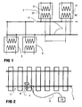
- Fig. 1 shows two separated by a rail insulation 12 Track sections.
- a track section is in the distance d from a transmitter / transmitter 5 a receiving circuit with a Receiver / transformer 6 connected.
- a typical area for such a distance d lies in the interval 25 m .. 2500 m.
- the thus modulated Carrier frequency when used in a track circuit as shown in FIG. 1 on the transmitting coil 51 as Part of a transformer 5 switched.
- the secondary transmission coil 52 as part of the transformer 5 is connected to the two rails. 3 a track section connected.
- the receiver / transmitter 6 has a receiving coil 62 and in the primary circuit Secondary circuit on a receiving coil 61.
- the principal Function of such a track circuit in DC or AC technology is the following: Responds to a quiet track circuit a receiving device at a free track and the Rail-mounted relay or electronic detection "picks up". If a wagon is on the track section, it will change the electrical conditions. It creates a shunt, so that by the receiving device only a small Residual current flows. This will determine that the section is occupied, since the jelly relay then no longer "attracts". This construction has the consequence that all frequently occurring Errors such as interruptions of the circuit (for example by a Line break or defective fuses) to one alleged lead occupied track section.
- This procedure in DC or AC technique has the disadvantage that reverse currents in the rails can simulate an occupancy, the do not represent any occupancy by an axle or vehicle.
- the spread signal modulated onto a carrier frequency band is broadband.
- the specified upper limit of the frequency band can be explained by the fact that above this frequency emission limits must be observed.
- the level of the signal S B 'received by the receiver 6 in the receiver coil 62 is dependent upon the presence of a wheel 1 in the immediate vicinity of the transmitter / receiver located on the rail. In a receiving device (not shown in the figures), this signal S B 'must be despread. This is generally much more complex than the spread.
- the transmission clock is directly present in the reception device, because transmission and reception devices can be realized directly next to one another or as an integrated device.
- This essential requirement is generally not the case for DSSS messaging.
- no special effort for synchronization is provided in the receiving device.
- the received signal S B ' is in turn XORed to the same Barker code B.
- the received signal S B ' has according to the figure 5 at the point i a curve S i .
- a non-ideal course also occurs in the other places, but this is not shown in FIG. 5, but is shown merely by way of example for location i.
- This signal S i deviates from the mean signal strength S Avg by D i .
- the deviation D i is then multiplied by -1 if the value of the Barker code at the position i is equal to 1.
- the result R i is calculated from this value added to the average signal strength S Avg .
- the transmitted spread S B can nevertheless be regenerated as information S.
- the following frequencies or a frequency band from the frequency band listed below are used for the transmission: 10 kHz .. 30 MHz.
- the information S is spread with another Barker code B 2 , this code comprising m 2 digits.
- the spread signal S B2 is modulated on a carrier frequency band disjoint with respect to the first carrier frequency band.
- the Barker Code B 2 no special conditions apply, in particular the lengths m and m 2 may be different. In this way, a redundant two-channel system for detecting a track occupancy is created, which is largely immune to interference on certain frequency bands and thereby optimally meets security requirements. Despite the redundancy, no second installation of facilities on the track is required. Such a second channel with another Barker code B 2 can be implemented with relatively little effort.
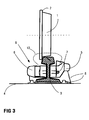
- the second embodiment of the present invention will be based on the "magnetic" implementation according to the Fig. 2 and 3 explained.
- the receiving coils 9a and 9b detect over the field lines 13, the spectrum emitted by the transmitting coil 5.
- the level This spectrum is dependent on the presence of a Rades or an object made of a magnetic material between transmitting coil 5 and receiving coil 9a and 9b.
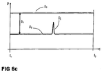
- FIG. 6 c shows a constant level P s over the frequency range, which is defined by the lower frequency f 1 and the upper frequency f 2 .
- the transmitting coil 5 is supplied via the aforementioned frequency range [f 1 .. f 12 ] this level.
- a reception level P S is shown in a momentary level distance P D , it is assumed that an interference field D f is present in a small subrange around a frequency f.
- the term "momentary" mentioned above means for the relevant frequency f at a certain time.
- This reception level occurs at a reception coil 9a or 9b.
- This interference field is of course part of the received signal S B , with the level P s ,. For clarification, however, this is designated in FIG.
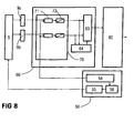
- FIG. 8 shows an evaluation of the frequency characteristics f a and f b generated according to FIGS. 6 a in an implementation with digital signal processors.
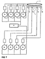
- the transmitting device 50 has a voltage-controlled oscillator 55 (VCO voltage controlled oscillator).
- a controller 56 generates a corresponding voltage curve for the desired frequency profile.
- Not shown in FIG. 9 is a possibly provided feedback in order to avoid transient or quasi-static interference fields detected in the receiver coils 9a and 9b.
- a transmission clock generator 54 is provided for determining the respective distance T ab from the two frequency curves f a , f b as well as for the repetition T REP .
- the receiver coils 9a and 9b are each connected to a broadband filter 71.
- the transmit clock generator is also connected to bandwidth attenuated filters 71 to supply the received level of the respective frequency to the A / D converters 72 in the respective time frame.
- the digital values of the levels at discrete time intervals are levels at specific frequencies, see FIG. 6c. Although the frequency is indicated on the abscissa, in a method with, for example, a linearly increasing frequency, this abscissa is also underlaid by a time axis.
- These digital levels are subjected to a reference storage 64 over time in order to be able to compensate for any aging phenomena.
- the time constant here is orders of magnitude of weeks or months.
- the above-mentioned digital signals are, as explained earlier on FIGS. 6a and 6c, used for wheel or axle recovery.
- the result is a value ⁇ 1.
- the sign contains the direction of travel.
- the long-term return of the stored reference values has the consequence that this embodiment of the present invention requires no external calibration.
- the aforementioned value ⁇ 1 is further evaluated in a known manner in the Achsoutheasternelektronik 80.
- FIG. 6b shows a logarithmic progression, the scale f 1 to f 2 being linear.
- a representation with a logarithmic scale would also have been possible, the graphical representation then appearing as "linear".
- the advantage of a logarithmic progression lies in the fact that the residence time in an assumed interference band f d1 and f d2 is shorter than in the linear time profile according to FIG. 6a. In this way, a statically known interference band can be additionally avoided.
- the respective emitted frequency response f a , f b , etc. is known, it would also be possible to determine by a detection and analysis of the disturbance field "the frequency response to be emitted so that the current, quasi-static interference field 6a and 6b, the frequency response over time is strictly monotonically increasing, but it is also possible to provide a frequency response that is either monotonically increasing, monotonically decreasing, or severe is monotonically decreasing.
- first course f a can also be ascending and the second course f b formed falling.
- the method described above can also be carried out with two channels.
- independent transmitting devices 6c and 6d are provided for a second channel, which generate a frequency curve f c and f d as shown in FIG. 6a.
- the corresponding courses f c and f d can be registered in the receiver coils 9c and 9d and analyzed or correlated in the receiver units 6c and 6b.
- This dual-channel design enables the required safety requirement with regard to redundancy and independence to be met.
- the transmitting coil 5 is a static element. A possible impairment of the function of the transmitting coil 5 can be determined from the transmitter side and is thus independent of signals of the receiving circuits.
Landscapes
- Engineering & Computer Science (AREA)
- Automation & Control Theory (AREA)
- Mechanical Engineering (AREA)
- Train Traffic Observation, Control, And Security (AREA)
- Arrangements For Transmission Of Measured Signals (AREA)
- Length Measuring Devices With Unspecified Measuring Means (AREA)
Claims (15)
- Procédé de constatation d'une occupation de voie par :
- A1
- un capteur (9) de roue qui est disposé sur un rail (3), qui comporte un émetteur (5) et un récepteur (6) et qui enregistre une variation du champ magnétique à la suite d'une roue (1) de chemin de fer qui passe sur le rail (3),
- A2
- un circuit de voie qui est formé de deux rails (3), qui a un émetteur (5) et un récepteur (6) et qui est court-circuité lors du passage d'un véhicule de chemin de fer, le court-circuit pouvant être enregistré dans le récepteur ;
- B
- l'émetteur (5) est alimenté en un signal (SB) qui est engendré dans une unité (50 ; 5a, 5b, ...) d'émission, qui est à bande large du point de vue spectral et qui contient une information (S) ;
- C
- des signaux (SB') enregistrés par le récepteur (6) sont envoyés à une unité (60 ; 6a, 6b, ...) de réception pour récupérer l'information (S) émise au stade B du procédé, l'unité (50 ; 5a, 5b, ...) d'émission et l'unité (60 ; 6a, 6b, ...) de réception étant couplées ;
- D
- on tire parti de niveaux différents qui se produisent du signal (SB') enregistré pour constater l'occupation de voie.
- Procédé suivant la revendication 1,
caractérisé en ce que
au stade B du procédé, l'information (S) à transmettre est étalée avec un code (B) en technique Direct Sequence spread Spectrum dans l'unité (50 ; 5a, 5b, ...) d'émission et est modulée sur une bande de fréquence porteuse. - Procédé suivant la revendication 2,
caractérisé en ce que
au stade C du procédé, pour le couplage de l'unité (50 ; 5a, 5b, ...) d'émission et de l'unité (60 ; 6a, 6b, ...) de réception, la cadence (54 ; 20) d'émission est envoyée à l'unité (60 ; 6a, 6b, ...) de réception. - Procédé suivant la revendication 2 ou 3,
caractérisé en ce que
au stade B du procédé, l'information (S) à transmettre est étalée avec deux codes (B, B2) différents et est modulée sur des bandes de fréquence porteuses disjointes. - Procédé suivant l'une des revendications 2 à 4,
caractérisé en ce que
la bande de fréquence porteuse a une plage de 10 kHz à 30 MHz. - Procédé suivant la revendication 1,
caractérisé en ce que
au stade B du procédé, l'information (S) à transmettre est codée dans l'unité (50 ; 5a, 5b, ...) d'émission par émission de deux courbes (Tab, fa, fb, ...) de fréquence successives, les deux courbes étant émises de manière répétitive (Trep). - Procédé suivant la revendication 6,
caractérisé en ce que
au stade B du procédé, l'information (S) à transmettre est codée dans l'unité (50 ; 5a, 5b, ...) d'émission par émission de quatre courbes (Tab, fa, fb, fc, fd) de fréquence qui se succèdent, les quatre courbes étant émises de manière répétitive (Trep). - Procédé suivant la revendication 6 ou 7,
caractérisé en ce que
il est prévu un générateur (20) pour l'émission répétitive et en ce que le générateur est couplé à l'unité (5a, 5b, ...) d'émission et à l'unité (6a, 6b, ...) de réception. - Procédé suivant l'une des revendications 6 à 8,
caractérisé en ce que
la courbe (fa, fb, ...) de fréquence est croissante linéairement ou décroissante linéairement en fonction du temps. - Procédé suivant l'une des revendications 6 à 8,
caractérisé en ce que
la courbe (fa, fb, ...) de fréquence est croissante logarithmiquement ou décroissante logarithmiquement en fonction du temps. - Procédé suivant l'une des revendications 6 à 8,
caractérisé en ce que
la courbe (fa, fb, ...) de fréquence est croissante de manière monotone ou décroissante de manière monotone en fonction du temps. - Procédé suivant l'une des revendications 6 à 11,
caractérisé en ce que
avant d'exécuter le stade B du procédé, un champ parasite détecté par le récepteur est analysé et en ce que, dans le stade B du procédé, la courbe (fa, fb, ...) de fréquence est fixée à l'extérieur ou au bord du champ parasite. - Procédé suivant l'une des revendications 6 à 12,
caractérisé en ce que
les courbes (fa, fb, ...) de fréquence sont mises dans une bande de 10 kHz à 10 MHz. - Procédé suivant l'une des revendications 1 à 13,
caractérisé en ce que
le capteur (9) de roue a pour la détection du sens du passage deux bobines (9a, 9b) de réception. - Procédé suivant l'une des revendications 1 à 13,
caractérisé en ce que
le capteur (9) de roue a pour la détection du sens de passage quatre bobines (9a, 9b, 9c, 9d) de réception.
Priority Applications (4)
| Application Number | Priority Date | Filing Date | Title |
|---|---|---|---|
| ES03009575T ES2247447T3 (es) | 2003-04-29 | 2003-04-29 | Procedimiento para la deteccion de la ocupacion de las vias ferreas. |
| DE50301090T DE50301090D1 (de) | 2003-04-29 | 2003-04-29 | Verfahren zur Detektion einer Gleisbelegung |
| AT03009575T ATE303277T1 (de) | 2003-04-29 | 2003-04-29 | Verfahren zur detektion einer gleisbelegung |
| EP03009575A EP1473208B1 (fr) | 2003-04-29 | 2003-04-29 | Procédé par la détection d'occupation de voie |
Applications Claiming Priority (1)
| Application Number | Priority Date | Filing Date | Title |
|---|---|---|---|
| EP03009575A EP1473208B1 (fr) | 2003-04-29 | 2003-04-29 | Procédé par la détection d'occupation de voie |
Publications (2)
| Publication Number | Publication Date |
|---|---|
| EP1473208A1 EP1473208A1 (fr) | 2004-11-03 |
| EP1473208B1 true EP1473208B1 (fr) | 2005-08-31 |
Family
ID=32981765
Family Applications (1)
| Application Number | Title | Priority Date | Filing Date |
|---|---|---|---|
| EP03009575A Expired - Lifetime EP1473208B1 (fr) | 2003-04-29 | 2003-04-29 | Procédé par la détection d'occupation de voie |
Country Status (4)
| Country | Link |
|---|---|
| EP (1) | EP1473208B1 (fr) |
| AT (1) | ATE303277T1 (fr) |
| DE (1) | DE50301090D1 (fr) |
| ES (1) | ES2247447T3 (fr) |
Families Citing this family (4)
| Publication number | Priority date | Publication date | Assignee | Title |
|---|---|---|---|---|
| DE102007031139A1 (de) * | 2007-06-29 | 2009-01-02 | Siemens Ag | Verfahren zur Erhöhung der Störsicherheit eines Radsensors und Radsensors zur Durchführung des Verfahrens |
| DE102008008028A1 (de) * | 2008-02-04 | 2009-11-26 | Siemens Aktiengesellschaft | Verfahren zur Erhöhung der Störsicherheit eines Radsensors und Radsensor zur Durchführung des Verfahrens |
| ES2531016B1 (es) * | 2014-03-18 | 2016-02-12 | Logistica Y Telecomunicacion, S.L. (Logytel) | Dispositivo sensor y procedimiento para detectar el paso de los ejes de los trenes por las vías |
| CN112214876B (zh) * | 2020-09-11 | 2024-12-27 | 通号城市轨道交通技术有限公司 | Cbtc信号测试系统中计轴建模方法、装置与电子设备 |
Family Cites Families (5)
| Publication number | Priority date | Publication date | Assignee | Title |
|---|---|---|---|---|
| DE3307689C2 (de) * | 1983-03-04 | 1984-12-20 | Standard Elektrik Lorenz Ag, 7000 Stuttgart | Schaltungsanordnung zum Betrieb eines induktiv arbeitenden Schienenkontakts |
| GB2149275B (en) * | 1983-10-26 | 1987-01-21 | Standard Telephones Cables Ltd | Identity card recognition system |
| JP3291607B2 (ja) * | 1994-12-28 | 2002-06-10 | 日本信号株式会社 | 列車検知装置 |
| DE19709840C2 (de) * | 1997-02-28 | 2001-10-04 | Siemens Ag | Einrichtung für die Achszählung zum Unterscheiden von Radbeeinflussungen und Nicht-Radbeeinflussungen |
| JP2001063573A (ja) * | 1999-08-27 | 2001-03-13 | Mitsubishi Electric Corp | 列車検知装置 |
-
2003
- 2003-04-29 DE DE50301090T patent/DE50301090D1/de not_active Expired - Lifetime
- 2003-04-29 AT AT03009575T patent/ATE303277T1/de active
- 2003-04-29 ES ES03009575T patent/ES2247447T3/es not_active Expired - Lifetime
- 2003-04-29 EP EP03009575A patent/EP1473208B1/fr not_active Expired - Lifetime
Also Published As
| Publication number | Publication date |
|---|---|
| ATE303277T1 (de) | 2005-09-15 |
| EP1473208A1 (fr) | 2004-11-03 |
| ES2247447T3 (es) | 2006-03-01 |
| DE50301090D1 (de) | 2005-10-06 |
Similar Documents
| Publication | Publication Date | Title |
|---|---|---|
| EP1058093B1 (fr) | Procédé et circuit d'alimentation et de surveillance du fonctionnement d'au moins un convertisseur de valeurs de mesure | |
| EP2084048B1 (fr) | Procédé et module d'exploitation de données de mesure dans des circuits électriques de voies de chemin de fer | |
| EP2403745B1 (fr) | Dispositifs permettant de détecter si un tronçon de voie est libre ou occupé et procédés pour faire fonctionner de tels dispositifs | |
| EP0983166A1 (fr) | Procede et dispositif pour transmettre des donnees numeriques entre un poste de mesure d'un systeme de protection des occupants d'un vehicule a moteur et un appareil de commande d'airbag | |
| EP2403744A1 (fr) | Dispositif permettant de détecter si un tronçon de voie est libre ou occupé et procédé pour faire fonctionner un tel dispositif | |
| DE69404218T2 (de) | Impedanzverbindung für Schienenwege | |
| EP3475142B1 (fr) | Dispositif de détection et procédé de détection d'une variation de champ magnétique | |
| EP2868548B1 (fr) | Procédé de surveillance d'un état de commutation d'un commutateur d'un système de sécurisation de train et système de sécurisation de train | |
| DE19709840C2 (de) | Einrichtung für die Achszählung zum Unterscheiden von Radbeeinflussungen und Nicht-Radbeeinflussungen | |
| DE10054745A1 (de) | Vorrichtung zur Umwandlung einer physikalischen Meßgröße in ein elektrisches Signal und Verfahren zur sicheren Übertragung von Sensorsignalen | |
| EP1473208A1 (fr) | Procédé par la détection d'occupation de voie | |
| DE2108496C3 (de) | Schaltungsanordnung zur ständigen Funktionskontrolle der Informationsverarbeitung und der Ausgabe von Datentelegrammen, insbesondere für prozeßrechnergesteuerte Eisenbahnsignalanlagen | |
| DE2602460A1 (de) | Steuereinrichtung fuer schienengebundenes fahrzeug | |
| EP3042805A1 (fr) | Dispositif de surveillance d'un réseau de bord | |
| DE4405809C2 (de) | Verfahren und Einrichtung zum Identifizieren einer Wechselspannung in einem Stromversorgungsnetz mit mehreren Wechselspannungen | |
| EP4417484A1 (fr) | Système de compteur d'essieux pour surveiller une section de voie d'un système de rails | |
| DE102011052807A1 (de) | Anordnung und Verfahren zur Steuerung einer induktiven Energieversorgungseinrichtung für Elektrofahrzeuge | |
| EP3587214B1 (fr) | Dispositif de commande de balises | |
| WO2007134992A1 (fr) | Dispositif permettant de déterminer si une partie de voie ferrée est libre ou occupée | |
| DE4423785C1 (de) | Verfahren zum Ermitteln der Position einer bestimmten Achse eines Schienenfahrzeuges auf einem Gleisabschnitt | |
| AT406856B (de) | Schaltungsanordnung zur überwachung von betriebskenndaten von eisenbahntechnischen sicherheitsmeldeanlagen | |
| DE3034659A1 (de) | Sicherheitsvorrichtung fuer ein spurgefuehrtes, gleisfreies fahrzeug und verfahren zum betrieb der vorrichtung | |
| EP2797802A1 (fr) | Dispositif de détection permettant de détecter une roue se déplaçant sur un rail de roulement | |
| DE102006035598B4 (de) | Verfahren zur Detektion des Belegt- oder Freizustandes eines Gleisabschnittes | |
| DE3412152A1 (de) | Schaltungsanordnung zum ueberwachen des vorhandenseins von schienenfahrzeugen innerhalb bestimmter gleisabschnitte |
Legal Events
| Date | Code | Title | Description |
|---|---|---|---|
| PUAI | Public reference made under article 153(3) epc to a published international application that has entered the european phase |
Free format text: ORIGINAL CODE: 0009012 |
|
| AK | Designated contracting states |
Kind code of ref document: A1 Designated state(s): AT BE BG CH CY CZ DE DK EE ES FI FR GB GR HU IE IT LI LU MC NL PT RO SE SI SK TR |
|
| AX | Request for extension of the european patent |
Extension state: AL LT LV MK |
|
| 17P | Request for examination filed |
Effective date: 20041118 |
|
| GRAP | Despatch of communication of intention to grant a patent |
Free format text: ORIGINAL CODE: EPIDOSNIGR1 |
|
| GRAS | Grant fee paid |
Free format text: ORIGINAL CODE: EPIDOSNIGR3 |
|
| GRAA | (expected) grant |
Free format text: ORIGINAL CODE: 0009210 |
|
| AKX | Designation fees paid |
Designated state(s): AT BE BG CH CY CZ DE DK EE ES FI FR GB GR HU IE IT LI LU MC NL PT RO SE SI SK TR |
|
| AK | Designated contracting states |
Kind code of ref document: B1 Designated state(s): AT BE BG CH CY CZ DE DK EE ES FI FR GB GR HU IE IT LI LU MC NL PT RO SE SI SK TR |
|
| PG25 | Lapsed in a contracting state [announced via postgrant information from national office to epo] |
Ref country code: RO Free format text: LAPSE BECAUSE OF FAILURE TO SUBMIT A TRANSLATION OF THE DESCRIPTION OR TO PAY THE FEE WITHIN THE PRESCRIBED TIME-LIMIT Effective date: 20050831 Ref country code: CZ Free format text: LAPSE BECAUSE OF FAILURE TO SUBMIT A TRANSLATION OF THE DESCRIPTION OR TO PAY THE FEE WITHIN THE PRESCRIBED TIME-LIMIT Effective date: 20050831 Ref country code: IE Free format text: LAPSE BECAUSE OF FAILURE TO SUBMIT A TRANSLATION OF THE DESCRIPTION OR TO PAY THE FEE WITHIN THE PRESCRIBED TIME-LIMIT Effective date: 20050831 Ref country code: FI Free format text: LAPSE BECAUSE OF FAILURE TO SUBMIT A TRANSLATION OF THE DESCRIPTION OR TO PAY THE FEE WITHIN THE PRESCRIBED TIME-LIMIT Effective date: 20050831 Ref country code: SK Free format text: LAPSE BECAUSE OF FAILURE TO SUBMIT A TRANSLATION OF THE DESCRIPTION OR TO PAY THE FEE WITHIN THE PRESCRIBED TIME-LIMIT Effective date: 20050831 Ref country code: SI Free format text: LAPSE BECAUSE OF FAILURE TO SUBMIT A TRANSLATION OF THE DESCRIPTION OR TO PAY THE FEE WITHIN THE PRESCRIBED TIME-LIMIT Effective date: 20050831 |
|
| REG | Reference to a national code |
Ref country code: CH Ref legal event code: EP Ref country code: GB Ref legal event code: FG4D Free format text: NOT ENGLISH |
|
| REG | Reference to a national code |
Ref country code: IE Ref legal event code: FG4D Free format text: LANGUAGE OF EP DOCUMENT: GERMAN |
|
| REF | Corresponds to: |
Ref document number: 50301090 Country of ref document: DE Date of ref document: 20051006 Kind code of ref document: P |
|
| GBT | Gb: translation of ep patent filed (gb section 77(6)(a)/1977) |
Effective date: 20051003 |
|
| PG25 | Lapsed in a contracting state [announced via postgrant information from national office to epo] |
Ref country code: DK Free format text: LAPSE BECAUSE OF FAILURE TO SUBMIT A TRANSLATION OF THE DESCRIPTION OR TO PAY THE FEE WITHIN THE PRESCRIBED TIME-LIMIT Effective date: 20051130 Ref country code: BG Free format text: LAPSE BECAUSE OF FAILURE TO SUBMIT A TRANSLATION OF THE DESCRIPTION OR TO PAY THE FEE WITHIN THE PRESCRIBED TIME-LIMIT Effective date: 20051130 Ref country code: GR Free format text: LAPSE BECAUSE OF FAILURE TO SUBMIT A TRANSLATION OF THE DESCRIPTION OR TO PAY THE FEE WITHIN THE PRESCRIBED TIME-LIMIT Effective date: 20051130 Ref country code: SE Free format text: LAPSE BECAUSE OF FAILURE TO SUBMIT A TRANSLATION OF THE DESCRIPTION OR TO PAY THE FEE WITHIN THE PRESCRIBED TIME-LIMIT Effective date: 20051130 |
|
| PG25 | Lapsed in a contracting state [announced via postgrant information from national office to epo] |
Ref country code: PT Free format text: LAPSE BECAUSE OF FAILURE TO SUBMIT A TRANSLATION OF THE DESCRIPTION OR TO PAY THE FEE WITHIN THE PRESCRIBED TIME-LIMIT Effective date: 20060223 |
|
| PG25 | Lapsed in a contracting state [announced via postgrant information from national office to epo] |
Ref country code: HU Free format text: LAPSE BECAUSE OF FAILURE TO SUBMIT A TRANSLATION OF THE DESCRIPTION OR TO PAY THE FEE WITHIN THE PRESCRIBED TIME-LIMIT Effective date: 20060301 |
|
| REG | Reference to a national code |
Ref country code: ES Ref legal event code: FG2A Ref document number: 2247447 Country of ref document: ES Kind code of ref document: T3 |
|
| REG | Reference to a national code |
Ref country code: IE Ref legal event code: FD4D |
|
| PG25 | Lapsed in a contracting state [announced via postgrant information from national office to epo] |
Ref country code: MC Free format text: LAPSE BECAUSE OF NON-PAYMENT OF DUE FEES Effective date: 20060430 Ref country code: BE Free format text: LAPSE BECAUSE OF NON-PAYMENT OF DUE FEES Effective date: 20060430 |
|
| ET | Fr: translation filed | ||
| PLBE | No opposition filed within time limit |
Free format text: ORIGINAL CODE: 0009261 |
|
| STAA | Information on the status of an ep patent application or granted ep patent |
Free format text: STATUS: NO OPPOSITION FILED WITHIN TIME LIMIT |
|
| 26N | No opposition filed |
Effective date: 20060601 |
|
| BERE | Be: lapsed |
Owner name: SIEMENS SCHWEIZ A.G. Effective date: 20060430 |
|
| PG25 | Lapsed in a contracting state [announced via postgrant information from national office to epo] |
Ref country code: EE Free format text: LAPSE BECAUSE OF FAILURE TO SUBMIT A TRANSLATION OF THE DESCRIPTION OR TO PAY THE FEE WITHIN THE PRESCRIBED TIME-LIMIT Effective date: 20050831 |
|
| PG25 | Lapsed in a contracting state [announced via postgrant information from national office to epo] |
Ref country code: TR Free format text: LAPSE BECAUSE OF FAILURE TO SUBMIT A TRANSLATION OF THE DESCRIPTION OR TO PAY THE FEE WITHIN THE PRESCRIBED TIME-LIMIT Effective date: 20050831 Ref country code: LU Free format text: LAPSE BECAUSE OF NON-PAYMENT OF DUE FEES Effective date: 20060429 |
|
| PG25 | Lapsed in a contracting state [announced via postgrant information from national office to epo] |
Ref country code: CY Free format text: LAPSE BECAUSE OF FAILURE TO SUBMIT A TRANSLATION OF THE DESCRIPTION OR TO PAY THE FEE WITHIN THE PRESCRIBED TIME-LIMIT Effective date: 20050831 |
|
| REG | Reference to a national code |
Ref country code: CH Ref legal event code: PCOW Free format text: SIEMENS SCHWEIZ AG;FREILAGERSTRASSE 40;8047 ZUERICH (CH) |
|
| REG | Reference to a national code |
Ref country code: FR Ref legal event code: PLFP Year of fee payment: 13 |
|
| PGFP | Annual fee paid to national office [announced via postgrant information from national office to epo] |
Ref country code: NL Payment date: 20150403 Year of fee payment: 13 |
|
| PGFP | Annual fee paid to national office [announced via postgrant information from national office to epo] |
Ref country code: ES Payment date: 20150520 Year of fee payment: 13 Ref country code: GB Payment date: 20150414 Year of fee payment: 13 Ref country code: DE Payment date: 20150619 Year of fee payment: 13 |
|
| PGFP | Annual fee paid to national office [announced via postgrant information from national office to epo] |
Ref country code: AT Payment date: 20150305 Year of fee payment: 13 Ref country code: IT Payment date: 20150428 Year of fee payment: 13 Ref country code: FR Payment date: 20150415 Year of fee payment: 13 |
|
| PGFP | Annual fee paid to national office [announced via postgrant information from national office to epo] |
Ref country code: CH Payment date: 20150702 Year of fee payment: 13 |
|
| REG | Reference to a national code |
Ref country code: DE Ref legal event code: R119 Ref document number: 50301090 Country of ref document: DE |
|
| REG | Reference to a national code |
Ref country code: CH Ref legal event code: PL |
|
| REG | Reference to a national code |
Ref country code: NL Ref legal event code: MM Effective date: 20160501 |
|
| REG | Reference to a national code |
Ref country code: AT Ref legal event code: MM01 Ref document number: 303277 Country of ref document: AT Kind code of ref document: T Effective date: 20160429 |
|
| GBPC | Gb: european patent ceased through non-payment of renewal fee |
Effective date: 20160429 |
|
| REG | Reference to a national code |
Ref country code: FR Ref legal event code: ST Effective date: 20161230 |
|
| PG25 | Lapsed in a contracting state [announced via postgrant information from national office to epo] |
Ref country code: DE Free format text: LAPSE BECAUSE OF NON-PAYMENT OF DUE FEES Effective date: 20161101 Ref country code: NL Free format text: LAPSE BECAUSE OF NON-PAYMENT OF DUE FEES Effective date: 20160501 Ref country code: LI Free format text: LAPSE BECAUSE OF NON-PAYMENT OF DUE FEES Effective date: 20160430 Ref country code: CH Free format text: LAPSE BECAUSE OF NON-PAYMENT OF DUE FEES Effective date: 20160430 Ref country code: GB Free format text: LAPSE BECAUSE OF NON-PAYMENT OF DUE FEES Effective date: 20160429 Ref country code: FR Free format text: LAPSE BECAUSE OF NON-PAYMENT OF DUE FEES Effective date: 20160502 |
|
| PG25 | Lapsed in a contracting state [announced via postgrant information from national office to epo] |
Ref country code: IT Free format text: LAPSE BECAUSE OF NON-PAYMENT OF DUE FEES Effective date: 20160429 Ref country code: AT Free format text: LAPSE BECAUSE OF NON-PAYMENT OF DUE FEES Effective date: 20160429 |
|
| PG25 | Lapsed in a contracting state [announced via postgrant information from national office to epo] |
Ref country code: ES Free format text: LAPSE BECAUSE OF NON-PAYMENT OF DUE FEES Effective date: 20160430 |
|
| REG | Reference to a national code |
Ref country code: ES Ref legal event code: FD2A Effective date: 20181204 |