EP1475500A1 - Absturzsicherung für Sektionaltor mit Gewichtsausgleichsfeder - Google Patents
Absturzsicherung für Sektionaltor mit Gewichtsausgleichsfeder Download PDFInfo
- Publication number
- EP1475500A1 EP1475500A1 EP04006431A EP04006431A EP1475500A1 EP 1475500 A1 EP1475500 A1 EP 1475500A1 EP 04006431 A EP04006431 A EP 04006431A EP 04006431 A EP04006431 A EP 04006431A EP 1475500 A1 EP1475500 A1 EP 1475500A1
- Authority
- EP
- European Patent Office
- Prior art keywords
- plate
- shaft
- spring
- swinging plate
- stem
- Prior art date
- Legal status (The legal status is an assumption and is not a legal conclusion. Google has not performed a legal analysis and makes no representation as to the accuracy of the status listed.)
- Withdrawn
Links
- 230000000284 resting effect Effects 0.000 claims description 10
- 230000008878 coupling Effects 0.000 claims description 4
- 238000010168 coupling process Methods 0.000 claims description 4
- 238000005859 coupling reaction Methods 0.000 claims description 4
- 238000010276 construction Methods 0.000 claims description 3
- 230000006866 deterioration Effects 0.000 claims description 2
- 239000004519 grease Substances 0.000 claims description 2
- 230000001050 lubricating effect Effects 0.000 claims description 2
- 238000006116 polymerization reaction Methods 0.000 claims description 2
- 238000006243 chemical reaction Methods 0.000 claims 1
- 230000007935 neutral effect Effects 0.000 claims 1
- 238000004804 winding Methods 0.000 description 2
- 238000010586 diagram Methods 0.000 description 1
- 230000002045 lasting effect Effects 0.000 description 1
- 239000000463 material Substances 0.000 description 1
- 230000007246 mechanism Effects 0.000 description 1
- 238000000034 method Methods 0.000 description 1
- 238000010008 shearing Methods 0.000 description 1
- 230000001960 triggered effect Effects 0.000 description 1
Images


Classifications
-
- E—FIXED CONSTRUCTIONS
- E06—DOORS, WINDOWS, SHUTTERS, OR ROLLER BLINDS IN GENERAL; LADDERS
- E06B—FIXED OR MOVABLE CLOSURES FOR OPENINGS IN BUILDINGS, VEHICLES, FENCES OR LIKE ENCLOSURES IN GENERAL, e.g. DOORS, WINDOWS, BLINDS, GATES
- E06B9/00—Screening or protective devices for wall or similar openings, with or without operating or securing mechanisms; Closures of similar construction
- E06B9/56—Operating, guiding or securing devices or arrangements for roll-type closures; Spring drums; Tape drums; Counterweighting arrangements therefor
- E06B9/80—Safety measures against dropping or unauthorised opening; Braking or immobilising devices; Devices for limiting unrolling
- E06B9/82—Safety measures against dropping or unauthorised opening; Braking or immobilising devices; Devices for limiting unrolling automatic
- E06B9/84—Safety measures against dropping or unauthorised opening; Braking or immobilising devices; Devices for limiting unrolling automatic against dropping
-
- E—FIXED CONSTRUCTIONS
- E05—LOCKS; KEYS; WINDOW OR DOOR FITTINGS; SAFES
- E05D—HINGES OR SUSPENSION DEVICES FOR DOORS, WINDOWS OR WINGS
- E05D13/00—Accessories for sliding or lifting wings, e.g. pulleys, safety catches
- E05D13/003—Anti-dropping devices
-
- E—FIXED CONSTRUCTIONS
- E05—LOCKS; KEYS; WINDOW OR DOOR FITTINGS; SAFES
- E05D—HINGES OR SUSPENSION DEVICES FOR DOORS, WINDOWS OR WINGS
- E05D13/00—Accessories for sliding or lifting wings, e.g. pulleys, safety catches
- E05D13/10—Counterbalance devices
- E05D13/12—Counterbalance devices with springs
- E05D13/1253—Counterbalance devices with springs with canted-coil torsion springs
- E05D13/1269—Spring safety devices
-
- E—FIXED CONSTRUCTIONS
- E05—LOCKS; KEYS; WINDOW OR DOOR FITTINGS; SAFES
- E05Y—INDEXING SCHEME ASSOCIATED WITH SUBCLASSES E05D AND E05F, RELATING TO CONSTRUCTION ELEMENTS, ELECTRIC CONTROL, POWER SUPPLY, POWER SIGNAL OR TRANSMISSION, USER INTERFACES, MOUNTING OR COUPLING, DETAILS, ACCESSORIES, AUXILIARY OPERATIONS NOT OTHERWISE PROVIDED FOR, APPLICATION THEREOF
- E05Y2900/00—Application of doors, windows, wings or fittings thereof
-
- E—FIXED CONSTRUCTIONS
- E05—LOCKS; KEYS; WINDOW OR DOOR FITTINGS; SAFES
- E05Y—INDEXING SCHEME ASSOCIATED WITH SUBCLASSES E05D AND E05F, RELATING TO CONSTRUCTION ELEMENTS, ELECTRIC CONTROL, POWER SUPPLY, POWER SIGNAL OR TRANSMISSION, USER INTERFACES, MOUNTING OR COUPLING, DETAILS, ACCESSORIES, AUXILIARY OPERATIONS NOT OTHERWISE PROVIDED FOR, APPLICATION THEREOF
- E05Y2900/00—Application of doors, windows, wings or fittings thereof
- E05Y2900/10—Application of doors, windows, wings or fittings thereof for buildings or parts thereof
- E05Y2900/106—Application of doors, windows, wings or fittings thereof for buildings or parts thereof for garages
Definitions
- the patent relates to anti-drop safety devices for sectional doors.
- Such springs are secured to one end of the shaft and on the other end to a plate integral with the door frame.
- the springs are pre-charged in such way that the maximum torsion value is reached when the leaf of the door is lowered, meaning that it is closed.
- the opening of the door is made easier because the weight of the same is almost completely balanced by the spring's torsion charge.
- the best known methods are those of interposing, between the plate integral with the door frame (hereinafter called fixed plate) and the end of the spring that was secured to said fixed plate, a further plate linked to the fixed plate with the option of a limited arc of rotation defined by the width of a slot in one of the two plates within which a shank going through said slot crossing the slot located to the other of the two plates can move.
- Said plate (hereinafter called swinging plate to facilitate the description) to which the end of the pre-charged torsion spring is secured, is turned to the spring's torsion direction of rotation and with the available shank stroke within the end of the slot.
- a third plate Integral with the shaft and positioned near the two plates above is located a third plate involved in its outer perimeter or near the perimeter in a coaxial position in relation to the shaft or its gearing or a sequence of anyhow configured slots or holes.
- the principle to be put into practice is that if the spring ruptures, the third plate integral with the shaft is caught up by a device brought by the fixed plate that will snap open so as to link it to the fixed plate.
- the device brought by the fixed plate designed to act onto the plate integral with the shaft, on a ruptured spring or a spring not pre-charged to a certain torsion value, lies on the same plane as the plate and moves on that plane.
- the signal to the device to trigger to lock the fixed plate to the plate integral with the shaft supporting the door leaf is given by the swinging plate that, as a consequence of the spring rupturing, is brought back to its resting position by the recoil that the spring rupturing causes.
- the swinging plate can be equipped with a recalling spring that, in the event of torsion spring rupturing through the rupturing recoil of the said torsion spring, facilitates bringing the said swinging plate back to its resting position.
- the function of the swinging plate given the position it acquires with the pre-charged spring in relation to the fixed plate, is that of operating with the locking devices getting them caught on the plate integral with the shaft of the door leaf.
- the devices that act on the same plane as the standard position of the shaft of the sectional door leaf are usually based on the principle of the pawl that operates in the perimeter teeth of the circular plate integral with the said shaft.
- Such devices from their position of inactivity, to insert in the spaces of the gearing of the plate (disk) integral with the shaft, start rotating approaching the periphery of said disk integral with the shaft.
- the devices Before managing to completely enter the cavity of a gear, the devices undergo a strong impact, which is distributed almost entirely over their ends, both pertaining to the devices and to the gearing of the wheel integral with the shaft.
- the main aim of this invention is to overcome the drawbacks described above and improve the effectiveness and safety.
- Another aim is fulfilled through a device design such that once the same has triggered there is no need for the replacement of many parts or even the replacement of most of the device, but just the replacement of the locking element easily and cheaply.
- the swinging plate instead of being mounted between the fixed plate and the plate (disk) integral with the shaft of the door leaf, is placed on the outside while now the fixed plate is mounted in the intermediate position.
- the swinging plate Following the rupturing of the torsion spring, the swinging plate, no longer kept in its current position, swings, getting in the opposite position and inserts the end of the stem, which is compelled to come out by a spring, in correspondence with a slot on the fixed plate.
- the stem once it has crossed the slot, touches the plate integral with the leaf shaft and gets inserted axially into the first cavity facing it.
- the stem seat is integrally supported by the swinging plate because the sliding of the stem coming out of its seat is facilitated by the recoil that the said swinging plate undergoes because of the rupturing of the spring.
- Another advantage attained by this patent is that the stem can be partially extracted from its seat to be deactivated even when the torsion spring is not pre-charged or is not mounted or is broken.
- a further advantage is due to the fact that in case of operation of the patent device, the job is limited to the replacement of the stem, unlike the devices produced according to the principle of the pawl for which, in case of deterioration, it is necessary to replace the whole device.
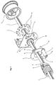
- Figure 1 axonometrically shows the exploded diagram of the parts making up the safety device.
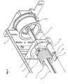
- Figure 2 axonometrically shows the assembled device seen from the swinging plate side and with the stem deactivated.
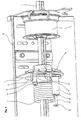
- Figure 3 axonometrically shows the assembled device seen in from the front.
- Figure 4 axonometrically shows the device seen from the side of the wheel integral with shaft of the door leaf.
- Figure 5 axonometrically shows the device seen from the side of the plate (geared disk) integral with the shaft of the door leaf with the stem inserted into a cavity in the periphery gearing of the above- mentioned plate integral with the shaft.
- FIG. 1 the shaft 1 of sectional door leaf is represented and lined up, but not mounted, the drum 2 for the winding of the door operation wire is also shown.
- Plate 3 can be noted, which is to be fixed to the door frame 14 (which is not represented here); plate 4 can be seen (geared disk), which is to be fitted to the shaft 1 so as to be integral with it.
- plate 4 On its periphery, plate 4 is concerned as if it were a gearwheel by a sequence of the cavities 15.
- the function of the cavities is to be engaged to stem 13 to lock the plate 4 they belong to.
- the fixed plate 3 can be noticed, neutrally crossed by shaft 1 configured as a right angle dihedral to be fixed to frame 14 (which is not represented here).
- Plate 3 is equipped with two curved configuring slots coaxial with shaft 1 and intended for the crossing of the ends of the stems 10 perpendicularly fixed to the swinging plate 5.
- Plate 3 is equipped with slot 18, which is as far from the shaft axis as the distance of stem 13 from the same axis of shaft 1, brought from the tubular seat 12 integral with the swinging plate 5.
- bracket 6 is connected to the end of spring 7 opposed to the end fixed to shaft 1. In the figure of spring 7 only some coils are represented.
- Figure 2 shows the assembled device seen from the swinging plate 5 side. You can notice plate 3 fixed to the door frame 14; you can also note drum 2 mounted and keyed on shaft 1.
- bracket 6 (connected to one end of spring 7) which is integral with the swinging plate 5.
- Plate 4 configured as a geared wheel, is not in view.
- Figure 3 that shows almost frontally the device, allows to point out the order of the reciprocal positioning of the swinging plate 5 and of the plate 4 integral with shaft 1 with respect to the central fixed plate 3.
- Figure 4 which shows the device seen from the side of plate 4 integral with shaft 1, highlights the coupling modes of the ends 10 of the stems integral with the swinging plate 5 in the slots 11 of the fixed plate 3. Furthermore, you can note the correspondence of the lining up of slot 18, through which stem 13 has to slide, with a cavity of wheel 4.
- Figure 5 shows the enlargement of the coupling that takes place between stem 13, which has crossed slot 18 of the fixed plate 3 and has entered a cavity 15 of plate 4, locking it.
- This coupling is obtained in the case the torsion spring is ruptured or is not pre-charged, so that the swinging plate 5 is positioned in its resting placement and the ends 10 of its stems are in the slots 11 of the fixed plate 3 from the opposite side of the pre-charged torsion spring 7 and stem 13, which has returned into position, is resting onto the fixed plate body.
Landscapes
- Engineering & Computer Science (AREA)
- Mechanical Engineering (AREA)
- Structural Engineering (AREA)
- Architecture (AREA)
- Civil Engineering (AREA)
- Thermistors And Varistors (AREA)
- Closing And Opening Devices For Wings, And Checks For Wings (AREA)
Applications Claiming Priority (2)
| Application Number | Priority Date | Filing Date | Title |
|---|---|---|---|
| ITPD20030052 ITPD20030052A1 (it) | 2003-03-17 | 2003-03-17 | Dispositivo di sicurezza anticaduta per portoni sezionali |
| ITPD20030052 | 2003-03-17 |
Publications (1)
| Publication Number | Publication Date |
|---|---|
| EP1475500A1 true EP1475500A1 (de) | 2004-11-10 |
Family
ID=32983231
Family Applications (1)
| Application Number | Title | Priority Date | Filing Date |
|---|---|---|---|
| EP04006431A Withdrawn EP1475500A1 (de) | 2003-03-17 | 2004-03-17 | Absturzsicherung für Sektionaltor mit Gewichtsausgleichsfeder |
Country Status (2)
| Country | Link |
|---|---|
| EP (1) | EP1475500A1 (de) |
| IT (1) | ITPD20030052A1 (de) |
Cited By (3)
| Publication number | Priority date | Publication date | Assignee | Title |
|---|---|---|---|---|
| EP1627976A2 (de) * | 2004-08-16 | 2006-02-22 | Dometic Corporation | Markise |
| EP1832702A1 (de) * | 2006-03-10 | 2007-09-12 | Bremet Brevetti Metecno S.P.A. | Sperrvorrichtung einer Tür |
| SE2130166A1 (sv) * | 2021-06-17 | 2022-12-18 | Anders Beyron | Fallskyddsanordning, samt vertikalgående industriport med fallskyddsanordning |
Citations (5)
| Publication number | Priority date | Publication date | Assignee | Title |
|---|---|---|---|---|
| EP0722031A1 (de) * | 1995-01-13 | 1996-07-17 | Hörmann Kg Dissen | Vorrichtung zur Überwachung einer vorgespannt betriebenen Torsionsfeder |
| EP0845575A1 (de) * | 1996-11-28 | 1998-06-03 | Michel Javey | Absturzsicherungsvorrichtung für vertikal einziehbare Verschlusseinrichtungen |
| DE20100666U1 (de) * | 2001-01-15 | 2001-03-22 | Cardo Door Production GmbH, 85368 Moosburg | Federüberwachungsvorrichtung |
| EP1213428A1 (de) * | 2000-12-07 | 2002-06-12 | Flexi-Force B.V. | Absturzsicherung |
| EP1270866A1 (de) * | 2001-06-28 | 2003-01-02 | BMJ S.a.r.l. | Fallschutzvorrichtung für einen aufrollbaren Verschluss |
-
2003
- 2003-03-17 IT ITPD20030052 patent/ITPD20030052A1/it unknown
-
2004
- 2004-03-17 EP EP04006431A patent/EP1475500A1/de not_active Withdrawn
Patent Citations (5)
| Publication number | Priority date | Publication date | Assignee | Title |
|---|---|---|---|---|
| EP0722031A1 (de) * | 1995-01-13 | 1996-07-17 | Hörmann Kg Dissen | Vorrichtung zur Überwachung einer vorgespannt betriebenen Torsionsfeder |
| EP0845575A1 (de) * | 1996-11-28 | 1998-06-03 | Michel Javey | Absturzsicherungsvorrichtung für vertikal einziehbare Verschlusseinrichtungen |
| EP1213428A1 (de) * | 2000-12-07 | 2002-06-12 | Flexi-Force B.V. | Absturzsicherung |
| DE20100666U1 (de) * | 2001-01-15 | 2001-03-22 | Cardo Door Production GmbH, 85368 Moosburg | Federüberwachungsvorrichtung |
| EP1270866A1 (de) * | 2001-06-28 | 2003-01-02 | BMJ S.a.r.l. | Fallschutzvorrichtung für einen aufrollbaren Verschluss |
Cited By (4)
| Publication number | Priority date | Publication date | Assignee | Title |
|---|---|---|---|---|
| EP1627976A2 (de) * | 2004-08-16 | 2006-02-22 | Dometic Corporation | Markise |
| EP1832702A1 (de) * | 2006-03-10 | 2007-09-12 | Bremet Brevetti Metecno S.P.A. | Sperrvorrichtung einer Tür |
| SE2130166A1 (sv) * | 2021-06-17 | 2022-12-18 | Anders Beyron | Fallskyddsanordning, samt vertikalgående industriport med fallskyddsanordning |
| SE546418C2 (sv) * | 2021-06-17 | 2024-10-29 | Anders Beyron | Fallskyddsanordning, samt vertikalgående industriport med fallskyddsanordning |
Also Published As
| Publication number | Publication date |
|---|---|
| ITPD20030052A1 (it) | 2004-09-18 |
Similar Documents
| Publication | Publication Date | Title |
|---|---|---|
| EP1237748B1 (de) | Rastbeschlag für einen fahrzeugsitz, insbesondere für einen kraftfahrzeugsitz | |
| ES2425374T3 (es) | Bisagra con un dispositivo de amortiguación | |
| US10004927B2 (en) | Retractable lanyard lock mechanism | |
| US20180147428A1 (en) | Retracting lifeline systems for use in tie-back anchoring | |
| US9970221B2 (en) | Door handle assembly for motor vehicle | |
| CN103306538B (zh) | 圆筒式锁具 | |
| EP2898164B1 (de) | Türschutzanordnung | |
| JP2009041902A (ja) | 旋回せん子および回転ロックヘッドを有するロックおよび再撃鉄起しアセンブリ、特に反跳の運動エネルギーを使用する慣性作動武器のためのアセンブリ | |
| EP1213428A1 (de) | Absturzsicherung | |
| US5688002A (en) | Concealed rod or cable surface latching exit device | |
| EP2602174B1 (de) | Vorrichtung zum Anheben von Erstzräden in Fahrzeuge | |
| ES2703561T3 (es) | Dispositivo de aseguramiento sobre cuerda utilizable en modo asegurador y en polea | |
| BRPI0614342A2 (pt) | lingüeta de fechadura que pode ser destravada, particularmente, para um mecanismo de fechadura de veìculo a motor | |
| US7975433B2 (en) | Door mount for a safe | |
| DE202016103567U1 (de) | Aufschlagsicherer Türöffner | |
| US4547008A (en) | Lock for refrigerator or the like which can be unlocked from inside thereof | |
| US20040118172A1 (en) | Combination lock | |
| NZ270234A (en) | Door lever handle rotatably connected to a trim housing and driving a cam therein which moves a slider linearly along a guide rod which also holds a stop plate | |
| WO2019158487A1 (en) | Improvements in damped hinge assemblies | |
| CN210483260U (zh) | 一种防猫眼的后锁组件 | |
| US2072582A (en) | Spring balancer | |
| EP1870542B1 (de) | Lukendeckelanordnung | |
| EP2374750B1 (de) | Handlauf für einen Rettungskorb zur Brandbekämpfung | |
| WO2021251895A1 (en) | Adapter for a locking device, and locking assembly comprising an adapter and a locking device | |
| DE2640782B2 (de) | Sicherungseinrichtung an Zündern |
Legal Events
| Date | Code | Title | Description |
|---|---|---|---|
| PUAI | Public reference made under article 153(3) epc to a published international application that has entered the european phase |
Free format text: ORIGINAL CODE: 0009012 |
|
| AK | Designated contracting states |
Kind code of ref document: A1 Designated state(s): AT BE BG CH CY CZ DE DK EE ES FI FR GB GR HU IE IT LI LU MC NL PL PT RO SE SI SK TR |
|
| AX | Request for extension of the european patent |
Extension state: AL LT LV MK |
|
| AKX | Designation fees paid | ||
| REG | Reference to a national code |
Ref country code: DE Ref legal event code: 8566 |
|
| STAA | Information on the status of an ep patent application or granted ep patent |
Free format text: STATUS: THE APPLICATION IS DEEMED TO BE WITHDRAWN |
|
| 18D | Application deemed to be withdrawn |
Effective date: 20050511 |