EP1270866A1 - Fallschutzvorrichtung für einen aufrollbaren Verschluss - Google Patents
Fallschutzvorrichtung für einen aufrollbaren Verschluss Download PDFInfo
- Publication number
- EP1270866A1 EP1270866A1 EP02291394A EP02291394A EP1270866A1 EP 1270866 A1 EP1270866 A1 EP 1270866A1 EP 02291394 A EP02291394 A EP 02291394A EP 02291394 A EP02291394 A EP 02291394A EP 1270866 A1 EP1270866 A1 EP 1270866A1
- Authority
- EP
- European Patent Office
- Prior art keywords
- spring
- finger
- coil
- blanks
- compensation
- Prior art date
- Legal status (The legal status is an assumption and is not a legal conclusion. Google has not performed a legal analysis and makes no representation as to the accuracy of the status listed.)
- Granted
Links
- 230000003068 static effect Effects 0.000 claims abstract description 39
- 230000000903 blocking effect Effects 0.000 claims description 26
- 238000006073 displacement reaction Methods 0.000 claims description 11
- 230000002093 peripheral effect Effects 0.000 claims description 6
- 229910000831 Steel Inorganic materials 0.000 claims description 4
- 239000010959 steel Substances 0.000 claims description 4
- 239000000463 material Substances 0.000 claims description 3
- 238000005728 strengthening Methods 0.000 claims description 2
- 210000002816 gill Anatomy 0.000 claims 1
- 238000004519 manufacturing process Methods 0.000 claims 1
- 230000006835 compression Effects 0.000 abstract 1
- 238000007906 compression Methods 0.000 abstract 1
- 210000000056 organ Anatomy 0.000 description 20
- 238000004804 winding Methods 0.000 description 8
- 230000006872 improvement Effects 0.000 description 5
- 230000002265 prevention Effects 0.000 description 4
- 230000006978 adaptation Effects 0.000 description 3
- 230000008901 benefit Effects 0.000 description 2
- 239000000470 constituent Substances 0.000 description 2
- 230000003656 anti-hair-loss Effects 0.000 description 1
- 238000012550 audit Methods 0.000 description 1
- 230000008878 coupling Effects 0.000 description 1
- 238000010168 coupling process Methods 0.000 description 1
- 238000005859 coupling reaction Methods 0.000 description 1
- 210000005069 ears Anatomy 0.000 description 1
- 230000000694 effects Effects 0.000 description 1
- 230000003100 immobilizing effect Effects 0.000 description 1
- 238000009434 installation Methods 0.000 description 1
- 238000002955 isolation Methods 0.000 description 1
- 238000012423 maintenance Methods 0.000 description 1
- 230000007246 mechanism Effects 0.000 description 1
- 239000002184 metal Substances 0.000 description 1
- 238000012986 modification Methods 0.000 description 1
- 230000004048 modification Effects 0.000 description 1
- 230000001105 regulatory effect Effects 0.000 description 1
- 239000000725 suspension Substances 0.000 description 1
- 230000009466 transformation Effects 0.000 description 1
- 238000000844 transformation Methods 0.000 description 1
Images




Classifications
-
- E—FIXED CONSTRUCTIONS
- E06—DOORS, WINDOWS, SHUTTERS, OR ROLLER BLINDS IN GENERAL; LADDERS
- E06B—FIXED OR MOVABLE CLOSURES FOR OPENINGS IN BUILDINGS, VEHICLES, FENCES OR LIKE ENCLOSURES IN GENERAL, e.g. DOORS, WINDOWS, BLINDS, GATES
- E06B9/00—Screening or protective devices for wall or similar openings, with or without operating or securing mechanisms; Closures of similar construction
- E06B9/56—Operating, guiding or securing devices or arrangements for roll-type closures; Spring drums; Tape drums; Counterweighting arrangements therefor
- E06B9/80—Safety measures against dropping or unauthorised opening; Braking or immobilising devices; Devices for limiting unrolling
- E06B9/82—Safety measures against dropping or unauthorised opening; Braking or immobilising devices; Devices for limiting unrolling automatic
- E06B9/84—Safety measures against dropping or unauthorised opening; Braking or immobilising devices; Devices for limiting unrolling automatic against dropping
-
- E—FIXED CONSTRUCTIONS
- E06—DOORS, WINDOWS, SHUTTERS, OR ROLLER BLINDS IN GENERAL; LADDERS
- E06B—FIXED OR MOVABLE CLOSURES FOR OPENINGS IN BUILDINGS, VEHICLES, FENCES OR LIKE ENCLOSURES IN GENERAL, e.g. DOORS, WINDOWS, BLINDS, GATES
- E06B9/00—Screening or protective devices for wall or similar openings, with or without operating or securing mechanisms; Closures of similar construction
- E06B9/56—Operating, guiding or securing devices or arrangements for roll-type closures; Spring drums; Tape drums; Counterweighting arrangements therefor
- E06B9/60—Spring drums operated only by closure members
Definitions
- the present invention relates to a device anti-fall of a structure closing apron flexible suitable for being wrapped around a system substantially cylindrical support mounted movable in rotation around a fixed shaft, usually above an opening to condemn.
- the invention finds an application particularly advantageous, but not exclusive, in the field of erasure closures vertical fitted to building accesses industrial and commercial.
- curtains or apron mean more generally any means capable of closing a opening, i.e. a plate, an assembly blades, grid etc ...
- the structural flexibility needed to the winding of this organ can come from directly from the intrinsic nature of the material the constituent and / or articulations linking different parts of it.
- the winding of the deck is traditionally made around at least one mobile mounted coil rotating on said fixed shaft.
- Each coil is also connected to the shaft fixed by means of a spring spiral type compensation, wound inside even of said coil.
- This elastic return means is responsible for at least partially counterbalance the weight of the apron restoring during the phase energy stored in the form of torque during the closing phase.
- an apron has a relatively heavy important, usually ranging from several tens to several hundred kilograms. Combined with a high falling speed, this mass constitutes a real danger for users.
- French patent application No. 2,739,656 describes however several restraint systems likely to perform this function.
- the principle of locking is identical for each embodiment described. It basically consists in positively coupling to the fixed shaft, the coil whose spring is failing, after a given angular displacement, of said coil, relative to means of specific locking. This movement, controlled by a return element mounted between the coil and the locking means, will then allow locking means audits to order the movement of a locking piece towards a wheel fixed ratchet forming a stop, thus achieving immobilization of the deck relative to the tree of the roll-up closure.
- each spring of compensation is integral with a blocking element movable mounted on the move on the reel corresponding, the blocking element being able to move towards a static organ integral with the fixed shaft in order to cooperate by blocking with a part forming a stop of said member static, said blocking element being held at distance from the static organ by the force of recall by the compensation spring.
- the compensation spring is indeed the only part ordering the asset or the displacement of the locking element relative to the coil. In other words, he ensures alone immobilization of the blocking element in passive position, it also controls only the displacement towards the static organ, and finally it alone guarantees that it will remain in position active; passive and active positions being those in which said blocking element and said static organ are respectively at distance and in contact with each other.
- the position of the locking element in relation to to the static organ therefore depends only and especially directly from the state of the spring of compensation.
- the compensation spring Under normal conditions of use, the compensation spring is continuously tensioned due to excess winding of the coil constituent, and this whatever the position of the apron. As also its internal end is fixed, the restoring force is not felt than at its outer end. It is indeed the only likely to move, for two reasons that it is secured to the blocking element mounted movable in displacement on the reel of a part, and that said coil is itself mounted movable in rotation around the other fixed shaft go. The only restoring force thus allows advantageously hold the locking element in passive position, i.e. away from the static organ. This balance remains perfectly stable as long as the spring of compensation retains its mechanical properties original.
- the compensation spring As the compensation spring is wound on itself when the closure works normally the volume it occupies inside of the coil is very much lower than that that it has at rest, that is to say when it is not subject to any winding constraint. Also, after rupture, it will tend to naturally return to its original form. In case of failure, there is therefore a substantially radial expansion of the spring compensation which tends to deviate as much as possible the axis around which it was wound. This movement continues until the deployment of the spring is stopped, due to limited space existing inside the coil.
- the locking element When it is no longer subjected to the force of recall exercised by the compensation spring, the locking element is therefore free from leave his passive position and move by compared to the coil on which it is mounted mobile, towards the static organ. it of course implies that it can be driven on the move through a moving organ. This is precisely what produced when the compensating spring breaks then comes alive with the double extension movement radial and rotation previously described.
- the locking element, secured at the end compensation spring, is then moved to the active position in which it cooperates by blocking with the static member.
- the locking element is kept in contact with the static organ thanks to the fact that the expansion radial compensation spring is limited by the small volume available inside the coil, and thus said spring comes very quickly hang against the portion of apron surrounding said coil, thereby immobilizing said blocking element.
- the retainer includes guide means capable of directing the movement of the locking element in the direction of the static member, in the event of a break in the spring compensation ; the planned displacement taking place between the passive position in which the element blocking is at a distance from the static organ and the active position in which said element of blocking is in contact with said static member.
- the compensation spring is animated by a complex movement resulting substantially of the combination between an expansion radial and rotation in the winding direction of the turn. Also, it is particularly advantageous to control the movement of its outer end so that the locking element mobile is safely and efficiently managed by direction of the static organ.
- the goal is here above all to avoid the risks of catching the compensation spring and / or element blocking with any element, present at inside the coil, other than the organ static. Guide means arranged so adequate advantageously achieve this goal.
- the invention aims to provide a variant as well as a certain number improvements made to the entire device.
- the invention relates to a device anti-fall of a closing apron intended to be wound around at least one mobile mounted coil rotating on a fixed shaft and connected to it through a compensation spring wound on itself between two blanks of the coil and whose inner end is integral with the shaft, while its outer end cooperates with a movable blocking element in displacement on said coil, so that that in case of failure of the spring of compensation, said element comes to cooperate by blocking with an abutment part of a member static integral with the fixed shaft and therefore with the apron, characterized in that the blocking element cooperating with the outer end of the spring compensation consists of an interposed finger between the two blanks, generally parallel, delimiting the coil, of which an external part cooperates with an elastic thrust member and of which an internal part cooperates with the end of the compensation spring, which finger is capable of moving axially along an axis parallel to that of the tree, between two positions, the one called unlocking in which it is kept away from the stopper part of the static organ, putting the pushing organ axial
- the present invention also relates to characteristics that will emerge during the description which will follow, and which should be considered in isolation or according to all their possible technical combinations.
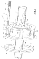
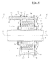
- the device 1 generally designated on the figures makes it possible to prohibit the fall of an apron of closure (not shown).
- the element of blocking 7 cooperating with the outer end 4b of the compensation spring 4 consists of a finger interposed between the two blanks 5, 6, generally parallel, delimiting the coil 2, of which an external part 7a is in connection with a elastic thrust member 10 and part of which internal 7b cooperates with the end 4b of the spring compensation 4.
- Finger 7 is likely to move axially along an axis parallel X, X 'to that Y, Y 'of the shaft 3, between two positions A, B, one A so-called unlocking in which it is kept at a distance from the stop part 8 of the static member 9, by putting the thrust member axial 10 under stress, by the force of return of spring 4 at its end external 4b.
- the finger 7 is cylindrical and made so stepped according to two different diameters D1, D2 delimiting a shoulder E between them.
- the area of smaller diameter D1 constitutes its internal part and that of the largest diameter D2 its part external.
- the retainer in the locking position A by the spring return force only at the level from its end 4b, takes place via of the shoulder E which constitutes a stop coming from against the field of said end 4b of the spring 4, when it is stretched therefore operational.
- the unlocking according to position B of finger 7 is carried out by releasing its shoulder E, when a relaxation of the spring winding force 4, in particular by rupture thereof, causing a development of its diameter.
- the area of largest diameter D2 of finger 7 constituting its external part 7a is in connection with the elastic pushing member 10 which is constituted by a spiral spring mounted in extension between the outer end of finger 7 and a fixed part of one of the blanks 5 constituting the coil 2 opposite to that 6 opposite the member static 8.
- the internal face of the blank 6 facing the static member 8 has a peripheral puncture 11 surrounding a through hole 11A of finger 7 in said blank 6 directed towards the stop part 8 of the static member 9, so as to constitute both a bearing at said finger 7 and a stop at compensation spring 4, preventing displacement lateral of it on the edge of the blank 6, likely to cause the spring 4 to jam and interfere with the operation of the device.
- the internal face of the blank 5 opposite to that 6 opposite the static member 9 comprises a peripheral puncture 12 surrounding the through hole correspondent 13 of finger 7 directed towards the organ of elastic thrust 10 thereof, in order to constitute a landing.
- FIG. 9 constituting section VIIIa, VIIIa of figure 8.
- the punctures 11 and 12 effectively contribute to stiffening the blanks 6 and 5 and consequently strengthen the maintenance of finger 7, in the unlocked position.
- its role is to maintain the end of the spring 4 which is tensioned.
- external hooking means 14, 15 of a end of extension spring 10, constituting the elastic thrust member are constituted by hooks 14, 15 obtained by deformation of blank material 5, around the through hole 13 of the finger 7. This improvement is particularly clearly visible in Figure 10 constituting a section along line VIIIb, VIIIb of Figure 8.
- each of the blanks 5, 6 integrates, for one 5 the hooking means 14, 15 of the spring 10 and one of the bearings 12 of the finger 7, and for the other 6 the other bearing 10 of the finger 7 and a stop of the compensation spring 4, consist of a unique piece, obtained by stamping from a flat sheet steel in a single operation.
- the blanks 5 and 6 are assembled together by through connecting bars 22 arranged between said blanks, then stapled by a deformation 23 of the end of said bars, after having crossed holes corresponding 24 of the blanks.
- These bars 22 are stiffened by a hollow stamping operation including the convex 22a is facing outwards and they contribute to the realization of the coil 2 by strengthening it.
- one 22A of these bars disposed near the punctures 11, 12 of the sides 6, 5, supporting the hooking finger 7, spring 4, although identical to the other bars 22, has the particularity of being returned so that its curved part is turned towards the interior and therefore its hollow portion 22Aa towards outside.
- said strip 22A is offset peripherally towards the interior compared to the others to allow at spring 4, near its end 4b, of pass over the strip 22A by covering its hollow portion 22Aa facing outwards, so towards the spring covering it. This is for to limit and control the expansion and friction, during a rupture of the spring.
- the organ static 9 has parts forming a stop 8 constituted by peripheral openings open to one of their ends and closed at the other end, in the direction of blocking to be obtained in the event for unlocking finger 7 which is housed in ear 8 closest, the pitch between two ears corresponding to an apron fall of less than thirty centimeters.
- the static organ 9 is obtained by stamping from a sheet of flat steel in a single operation.
- the organ static 9 is made integral with the shaft 3 by through the legs 16 extending axially from the body of the static member 9 and which are drilled with holes 17 for fixing to the shaft.
- the coil is held in place on the shaft 3 no only by the static member 9 fixed on this tree but also, on the contrary, by a piece of fixing 18 from which also comes from legs 19 in which holes are made 20 for fixing on the same shaft 3, trapping thus the coil and the fall prevention device according to the invention.
Landscapes
- Engineering & Computer Science (AREA)
- Structural Engineering (AREA)
- Architecture (AREA)
- Civil Engineering (AREA)
- Pivots And Pivotal Connections (AREA)
- Operating, Guiding And Securing Of Roll- Type Closing Members (AREA)
- Rolls And Other Rotary Bodies (AREA)
- Details Of Aerials (AREA)
- Springs (AREA)
- Casting Or Compression Moulding Of Plastics Or The Like (AREA)
- Ladders (AREA)
- Earth Drilling (AREA)
- Warping, Beaming, Or Leasing (AREA)
- Discharge Heating (AREA)
- Replacement Of Web Rolls (AREA)
Applications Claiming Priority (2)
| Application Number | Priority Date | Filing Date | Title |
|---|---|---|---|
| FR0108711 | 2001-06-28 | ||
| FR0108711A FR2826688B1 (fr) | 2001-06-28 | 2001-06-28 | Dispositif anti-chute pour fermeture a enroulement |
Publications (2)
| Publication Number | Publication Date |
|---|---|
| EP1270866A1 true EP1270866A1 (de) | 2003-01-02 |
| EP1270866B1 EP1270866B1 (de) | 2008-03-05 |
Family
ID=8864997
Family Applications (1)
| Application Number | Title | Priority Date | Filing Date |
|---|---|---|---|
| EP02291394A Expired - Lifetime EP1270866B1 (de) | 2001-06-28 | 2002-06-06 | Fallschutzvorrichtung für einen aufrollbaren Verschluss |
Country Status (6)
| Country | Link |
|---|---|
| EP (1) | EP1270866B1 (de) |
| AT (1) | ATE388298T1 (de) |
| DE (1) | DE60225377T2 (de) |
| ES (1) | ES2302789T3 (de) |
| FR (1) | FR2826688B1 (de) |
| PT (1) | PT1270866E (de) |
Cited By (10)
| Publication number | Priority date | Publication date | Assignee | Title |
|---|---|---|---|---|
| EP1475500A1 (de) * | 2003-03-17 | 2004-11-10 | Ballan S.p.A. | Absturzsicherung für Sektionaltor mit Gewichtsausgleichsfeder |
| EP1591617A1 (de) * | 2004-04-28 | 2005-11-02 | Mario Gnaccarini | Vorrichtung zur Befestigung einer Feder für Rolläden und Tore |
| WO2007043069A1 (en) * | 2005-10-11 | 2007-04-19 | Mario Gnaccarini | Spring-holder device for roller shutters and gates |
| EP1978202A1 (de) * | 2007-04-03 | 2008-10-08 | Mario Gnaccarini | Federhalterungsvorrichtung für Rolltore oder Rolltüren und Herstellungsverfahren für eine solche Vorrichtung |
| ITBO20120419A1 (it) * | 2012-07-31 | 2014-02-01 | Masinara S P A | Dispositivo di supporto di una molla di una serranda avvolgibile. |
| ITBO20130065A1 (it) * | 2013-02-14 | 2014-08-15 | Masinara S P A | Scatola portamolla di una serranda avvolgibile e relativi kit e metodo di assemblaggio. |
| WO2014203287A1 (en) | 2013-06-20 | 2014-12-24 | Conegliano Serramenti S.R.L. | Anti-drop safety device against torsion spring break in rolling shutter |
| ITUA20164191A1 (it) * | 2016-06-08 | 2017-12-08 | Masinara S P A | Elemento di protezione per le scatole portamolla di una serranda. |
| IT201600130739A1 (it) * | 2016-12-23 | 2018-06-23 | Masinara S P A | Attrezzo e metodo per il precaricamento di una molla interna ad una scatola portamolla per serrande |
| IT201800009646A1 (it) * | 2018-10-23 | 2020-04-23 | Antonino Siclari | Nuovo dispositivo per serrande e/o avvolgibili |
Families Citing this family (2)
| Publication number | Priority date | Publication date | Assignee | Title |
|---|---|---|---|---|
| FR2871840B1 (fr) | 2004-06-22 | 2006-08-11 | Bmj Sarl | Systeme de deblocage d'un dispositif anti-chute pour fermeture a enroulement |
| FR2884279B1 (fr) * | 2005-04-06 | 2007-05-25 | Michel Javey | Dispositif anti-chute pour fermeture a enroulement avec ou sans systeme de deblocage |
Citations (2)
| Publication number | Priority date | Publication date | Assignee | Title |
|---|---|---|---|---|
| FR2627801A1 (fr) * | 1988-02-29 | 1989-09-01 | Zurfluh Feller Sa Ets | Perfectionnements apportes aux rideaux metalliques et aux grilles enroulables a equilibrage par ressorts plats |
| EP0845575A1 (de) * | 1996-11-28 | 1998-06-03 | Michel Javey | Absturzsicherungsvorrichtung für vertikal einziehbare Verschlusseinrichtungen |
Family Cites Families (2)
| Publication number | Priority date | Publication date | Assignee | Title |
|---|---|---|---|---|
| FR2739656B1 (fr) | 1995-10-09 | 1997-11-21 | Tournier Gerard | Dispositif d'actionnement d'une fermeture a enroulement |
| FR2772070B1 (fr) | 1997-12-09 | 2000-01-07 | Michel Javey | Dispositif de retenue pour fermeture a enroulement |
-
2001
- 2001-06-28 FR FR0108711A patent/FR2826688B1/fr not_active Expired - Fee Related
-
2002
- 2002-06-06 PT PT02291394T patent/PT1270866E/pt unknown
- 2002-06-06 DE DE60225377T patent/DE60225377T2/de not_active Expired - Fee Related
- 2002-06-06 ES ES02291394T patent/ES2302789T3/es not_active Expired - Lifetime
- 2002-06-06 AT AT02291394T patent/ATE388298T1/de not_active IP Right Cessation
- 2002-06-06 EP EP02291394A patent/EP1270866B1/de not_active Expired - Lifetime
Patent Citations (2)
| Publication number | Priority date | Publication date | Assignee | Title |
|---|---|---|---|---|
| FR2627801A1 (fr) * | 1988-02-29 | 1989-09-01 | Zurfluh Feller Sa Ets | Perfectionnements apportes aux rideaux metalliques et aux grilles enroulables a equilibrage par ressorts plats |
| EP0845575A1 (de) * | 1996-11-28 | 1998-06-03 | Michel Javey | Absturzsicherungsvorrichtung für vertikal einziehbare Verschlusseinrichtungen |
Cited By (11)
| Publication number | Priority date | Publication date | Assignee | Title |
|---|---|---|---|---|
| EP1475500A1 (de) * | 2003-03-17 | 2004-11-10 | Ballan S.p.A. | Absturzsicherung für Sektionaltor mit Gewichtsausgleichsfeder |
| EP1591617A1 (de) * | 2004-04-28 | 2005-11-02 | Mario Gnaccarini | Vorrichtung zur Befestigung einer Feder für Rolläden und Tore |
| WO2007043069A1 (en) * | 2005-10-11 | 2007-04-19 | Mario Gnaccarini | Spring-holder device for roller shutters and gates |
| EP1978202A1 (de) * | 2007-04-03 | 2008-10-08 | Mario Gnaccarini | Federhalterungsvorrichtung für Rolltore oder Rolltüren und Herstellungsverfahren für eine solche Vorrichtung |
| ITBO20120419A1 (it) * | 2012-07-31 | 2014-02-01 | Masinara S P A | Dispositivo di supporto di una molla di una serranda avvolgibile. |
| ITBO20130065A1 (it) * | 2013-02-14 | 2014-08-15 | Masinara S P A | Scatola portamolla di una serranda avvolgibile e relativi kit e metodo di assemblaggio. |
| WO2014125414A1 (en) * | 2013-02-14 | 2014-08-21 | Masinara S.P.A. | Spring-holder box of a roller shutter and related assembly kit and method |
| WO2014203287A1 (en) | 2013-06-20 | 2014-12-24 | Conegliano Serramenti S.R.L. | Anti-drop safety device against torsion spring break in rolling shutter |
| ITUA20164191A1 (it) * | 2016-06-08 | 2017-12-08 | Masinara S P A | Elemento di protezione per le scatole portamolla di una serranda. |
| IT201600130739A1 (it) * | 2016-12-23 | 2018-06-23 | Masinara S P A | Attrezzo e metodo per il precaricamento di una molla interna ad una scatola portamolla per serrande |
| IT201800009646A1 (it) * | 2018-10-23 | 2020-04-23 | Antonino Siclari | Nuovo dispositivo per serrande e/o avvolgibili |
Also Published As
| Publication number | Publication date |
|---|---|
| DE60225377T2 (de) | 2009-03-12 |
| ES2302789T3 (es) | 2008-08-01 |
| FR2826688A1 (fr) | 2003-01-03 |
| PT1270866E (pt) | 2008-04-08 |
| ATE388298T1 (de) | 2008-03-15 |
| DE60225377D1 (de) | 2008-04-17 |
| EP1270866B1 (de) | 2008-03-05 |
| FR2826688B1 (fr) | 2004-01-23 |
Similar Documents
| Publication | Publication Date | Title |
|---|---|---|
| EP1270866B1 (de) | Fallschutzvorrichtung für einen aufrollbaren Verschluss | |
| WO2018109311A1 (fr) | Dispositif déflecteur aérodynamique pour roue de véhicule automobile | |
| FR2931403A1 (fr) | Dispositif d'absorption de choc et siege comportant un tel dispositif | |
| EP0845575B1 (de) | Absturzsicherungsvorrichtung für vertikal einziehbare Verschlusseinrichtungen | |
| EP0768445B1 (de) | Aufrollbare Verschlusseinrichtung mit Festwelle, Federgewichtsausgleich und Verriegelungseinrichtung | |
| EP0922832B1 (de) | Fangvorrichtung für rollbare Verschlussvorrichtungen | |
| EP1816294B1 (de) | Federgehäuse einer Fallschutzvorrichtung für Rollläden mit vertikaler Bewegungsrichtung | |
| CA3149948A1 (fr) | Nacelle, notamment nacelle elevatrice | |
| EP1030028B1 (de) | Fangvorrichtung für eine vertikal bewegbare Verschlusseinrichtung | |
| EP2017431A2 (de) | Federgehäuse einer Fallschutzvorrichtung für Rollläden mit vertikaler Bewegungsrichtung, das mit einer Sicherung ausgestattet ist und entsprechende Sicherungselemente | |
| WO2008041097A2 (fr) | Dispositif d'enroulement de cordon de suspension de store | |
| EP3032010B1 (de) | Schloss für einen Öffnungsflügel eines Kraftfahrzeugs | |
| EP2230372B1 (de) | Sicherheitsschleuse | |
| EP1609941A1 (de) | System zum Entriegeln einer Fallschutzvorrichtung für einen aufrollbaren Verschluss | |
| FR2949498A1 (fr) | Dispositif d'ouverture d'un ouvrant de vehicule automobile, et ouvrant equipe d'un tel dispositif. | |
| EP1609940B1 (de) | Abfallsicherheitsvorrichtung eines Rollvorhangs | |
| EP1956180A1 (de) | Vorrichtung mit um eine Walze aufrollbarem Rollladen | |
| EP1710390A2 (de) | Fallschutzvorrichtung für einen aufrollbaren Verschluss mit oder ohne Entriegelungssystem | |
| EP0369904B1 (de) | Von einem Schnurführungsbügel gesteuerte Angelwinde | |
| FR3113918A1 (fr) | Dispositif de butoirs de porte | |
| BE525986A (de) | ||
| FR2895387A1 (fr) | Dispositif d'enroulement, notamment pour store de protection tel que pare-soleil ou cache bagage | |
| FR2793838A1 (fr) | Dispositif de securite anti-chute pour fermetures a effacement vertical | |
| FR2997718A1 (fr) | Dispositif d'attelage pour volet roulant permettant la liaison entre le tablier et l'arbre d'enroulement du volet | |
| EP1241319A1 (de) | Sicherheitseinrichtung für eine Schliess- oder Sonnenschutzeinrichtung und Bedienungseinheit dieser Einrichtung |
Legal Events
| Date | Code | Title | Description |
|---|---|---|---|
| PUAI | Public reference made under article 153(3) epc to a published international application that has entered the european phase |
Free format text: ORIGINAL CODE: 0009012 |
|
| AK | Designated contracting states |
Kind code of ref document: A1 Designated state(s): AT BE CH CY DE DK ES FI FR GB GR IE IT LI LU MC NL PT SE TR |
|
| AX | Request for extension of the european patent |
Free format text: AL;LT;LV;MK;RO;SI |
|
| 17P | Request for examination filed |
Effective date: 20030502 |
|
| AKX | Designation fees paid |
Designated state(s): AT BE CH CY DE DK ES FI FR GB GR IE IT LI LU MC NL PT SE TR |
|
| RAP1 | Party data changed (applicant data changed or rights of an application transferred) |
Owner name: JAVEY, MICHEL |
|
| RIN1 | Information on inventor provided before grant (corrected) |
Inventor name: JAVEY, MICHEL |
|
| 111L | Licence recorded |
Free format text: 0100 FERMETURES JAVEY SAS Effective date: 20050217 |
|
| GRAP | Despatch of communication of intention to grant a patent |
Free format text: ORIGINAL CODE: EPIDOSNIGR1 |
|
| GRAS | Grant fee paid |
Free format text: ORIGINAL CODE: EPIDOSNIGR3 |
|
| GRAA | (expected) grant |
Free format text: ORIGINAL CODE: 0009210 |
|
| AK | Designated contracting states |
Kind code of ref document: B1 Designated state(s): AT BE CH CY DE DK ES FI FR GB GR IE IT LI LU MC NL PT SE TR |
|
| REG | Reference to a national code |
Ref country code: GB Ref legal event code: FG4D Free format text: NOT ENGLISH |
|
| REG | Reference to a national code |
Ref country code: CH Ref legal event code: EP |
|
| REG | Reference to a national code |
Ref country code: PT Ref legal event code: SC4A Free format text: AVAILABILITY OF NATIONAL TRANSLATION Effective date: 20080328 |
|
| REG | Reference to a national code |
Ref country code: IE Ref legal event code: FG4D Free format text: LANGUAGE OF EP DOCUMENT: FRENCH |
|
| REF | Corresponds to: |
Ref document number: 60225377 Country of ref document: DE Date of ref document: 20080417 Kind code of ref document: P |
|
| REG | Reference to a national code |
Ref country code: CH Ref legal event code: NV Representative=s name: WILLIAM BLANC & CIE CONSEILS EN PROPRIETE INDUSTRI |
|
| PG25 | Lapsed in a contracting state [announced via postgrant information from national office to epo] |
Ref country code: FI Free format text: LAPSE BECAUSE OF FAILURE TO SUBMIT A TRANSLATION OF THE DESCRIPTION OR TO PAY THE FEE WITHIN THE PRESCRIBED TIME-LIMIT Effective date: 20080305 |
|
| PGFP | Annual fee paid to national office [announced via postgrant information from national office to epo] |
Ref country code: CH Payment date: 20080527 Year of fee payment: 7 Ref country code: ES Payment date: 20080606 Year of fee payment: 7 |
|
| REG | Reference to a national code |
Ref country code: ES Ref legal event code: FG2A Ref document number: 2302789 Country of ref document: ES Kind code of ref document: T3 |
|
| PG25 | Lapsed in a contracting state [announced via postgrant information from national office to epo] |
Ref country code: AT Free format text: LAPSE BECAUSE OF FAILURE TO SUBMIT A TRANSLATION OF THE DESCRIPTION OR TO PAY THE FEE WITHIN THE PRESCRIBED TIME-LIMIT Effective date: 20080305 |
|
| NLV1 | Nl: lapsed or annulled due to failure to fulfill the requirements of art. 29p and 29m of the patents act | ||
| PGFP | Annual fee paid to national office [announced via postgrant information from national office to epo] |
Ref country code: IT Payment date: 20080614 Year of fee payment: 7 Ref country code: BE Payment date: 20080528 Year of fee payment: 7 Ref country code: PT Payment date: 20080528 Year of fee payment: 7 |
|
| REG | Reference to a national code |
Ref country code: IE Ref legal event code: FD4D |
|
| PG25 | Lapsed in a contracting state [announced via postgrant information from national office to epo] |
Ref country code: NL Free format text: LAPSE BECAUSE OF FAILURE TO SUBMIT A TRANSLATION OF THE DESCRIPTION OR TO PAY THE FEE WITHIN THE PRESCRIBED TIME-LIMIT Effective date: 20080305 Ref country code: SE Free format text: LAPSE BECAUSE OF FAILURE TO SUBMIT A TRANSLATION OF THE DESCRIPTION OR TO PAY THE FEE WITHIN THE PRESCRIBED TIME-LIMIT Effective date: 20080605 |
|
| PGFP | Annual fee paid to national office [announced via postgrant information from national office to epo] |
Ref country code: GB Payment date: 20080527 Year of fee payment: 7 |
|
| PLBE | No opposition filed within time limit |
Free format text: ORIGINAL CODE: 0009261 |
|
| STAA | Information on the status of an ep patent application or granted ep patent |
Free format text: STATUS: NO OPPOSITION FILED WITHIN TIME LIMIT |
|
| PG25 | Lapsed in a contracting state [announced via postgrant information from national office to epo] |
Ref country code: IE Free format text: LAPSE BECAUSE OF FAILURE TO SUBMIT A TRANSLATION OF THE DESCRIPTION OR TO PAY THE FEE WITHIN THE PRESCRIBED TIME-LIMIT Effective date: 20080305 Ref country code: DK Free format text: LAPSE BECAUSE OF FAILURE TO SUBMIT A TRANSLATION OF THE DESCRIPTION OR TO PAY THE FEE WITHIN THE PRESCRIBED TIME-LIMIT Effective date: 20080305 Ref country code: MC Free format text: LAPSE BECAUSE OF NON-PAYMENT OF DUE FEES Effective date: 20080630 |
|
| 26N | No opposition filed |
Effective date: 20081208 |
|
| PG25 | Lapsed in a contracting state [announced via postgrant information from national office to epo] |
Ref country code: DE Free format text: LAPSE BECAUSE OF NON-PAYMENT OF DUE FEES Effective date: 20090101 |
|
| PG25 | Lapsed in a contracting state [announced via postgrant information from national office to epo] |
Ref country code: CY Free format text: LAPSE BECAUSE OF FAILURE TO SUBMIT A TRANSLATION OF THE DESCRIPTION OR TO PAY THE FEE WITHIN THE PRESCRIBED TIME-LIMIT Effective date: 20080305 |
|
| REG | Reference to a national code |
Ref country code: PT Ref legal event code: MM4A Free format text: LAPSE DUE TO NON-PAYMENT OF FEES Effective date: 20091207 |
|
| BERE | Be: lapsed |
Owner name: JAVEY, MICHEL Effective date: 20090630 |
|
| REG | Reference to a national code |
Ref country code: CH Ref legal event code: PL |
|
| GBPC | Gb: european patent ceased through non-payment of renewal fee |
Effective date: 20090606 |
|
| PG25 | Lapsed in a contracting state [announced via postgrant information from national office to epo] |
Ref country code: PT Free format text: LAPSE BECAUSE OF NON-PAYMENT OF DUE FEES Effective date: 20091207 |
|
| PG25 | Lapsed in a contracting state [announced via postgrant information from national office to epo] |
Ref country code: LI Free format text: LAPSE BECAUSE OF NON-PAYMENT OF DUE FEES Effective date: 20090630 Ref country code: CH Free format text: LAPSE BECAUSE OF NON-PAYMENT OF DUE FEES Effective date: 20090630 |
|
| PG25 | Lapsed in a contracting state [announced via postgrant information from national office to epo] |
Ref country code: GB Free format text: LAPSE BECAUSE OF NON-PAYMENT OF DUE FEES Effective date: 20090606 |
|
| PG25 | Lapsed in a contracting state [announced via postgrant information from national office to epo] |
Ref country code: BE Free format text: LAPSE BECAUSE OF NON-PAYMENT OF DUE FEES Effective date: 20090630 |
|
| PG25 | Lapsed in a contracting state [announced via postgrant information from national office to epo] |
Ref country code: LU Free format text: LAPSE BECAUSE OF NON-PAYMENT OF DUE FEES Effective date: 20080606 |
|
| REG | Reference to a national code |
Ref country code: ES Ref legal event code: FD2A Effective date: 20090608 |
|
| PG25 | Lapsed in a contracting state [announced via postgrant information from national office to epo] |
Ref country code: TR Free format text: LAPSE BECAUSE OF FAILURE TO SUBMIT A TRANSLATION OF THE DESCRIPTION OR TO PAY THE FEE WITHIN THE PRESCRIBED TIME-LIMIT Effective date: 20080305 |
|
| PG25 | Lapsed in a contracting state [announced via postgrant information from national office to epo] |
Ref country code: ES Free format text: LAPSE BECAUSE OF NON-PAYMENT OF DUE FEES Effective date: 20090608 Ref country code: GR Free format text: LAPSE BECAUSE OF FAILURE TO SUBMIT A TRANSLATION OF THE DESCRIPTION OR TO PAY THE FEE WITHIN THE PRESCRIBED TIME-LIMIT Effective date: 20080606 |
|
| PG25 | Lapsed in a contracting state [announced via postgrant information from national office to epo] |
Ref country code: IT Free format text: LAPSE BECAUSE OF NON-PAYMENT OF DUE FEES Effective date: 20090606 |
|
| PGFP | Annual fee paid to national office [announced via postgrant information from national office to epo] |
Ref country code: FR Payment date: 20110630 Year of fee payment: 10 |
|
| REG | Reference to a national code |
Ref country code: FR Ref legal event code: ST Effective date: 20130228 |
|
| PG25 | Lapsed in a contracting state [announced via postgrant information from national office to epo] |
Ref country code: FR Free format text: LAPSE BECAUSE OF NON-PAYMENT OF DUE FEES Effective date: 20120702 |
|
| REG | Reference to a national code |
Ref country code: CH Ref legal event code: PK Free format text: COMPLETEMENT D'ENREGISTREMENT DE LICENCE: LICENCE EXCLUSIVE |