EP1475809A2 - Transformateur, dispositif de conversion de puissance et appareil de génération d'énergie solaire l'utilisant - Google Patents
Transformateur, dispositif de conversion de puissance et appareil de génération d'énergie solaire l'utilisant Download PDFInfo
- Publication number
- EP1475809A2 EP1475809A2 EP04010787A EP04010787A EP1475809A2 EP 1475809 A2 EP1475809 A2 EP 1475809A2 EP 04010787 A EP04010787 A EP 04010787A EP 04010787 A EP04010787 A EP 04010787A EP 1475809 A2 EP1475809 A2 EP 1475809A2
- Authority
- EP
- European Patent Office
- Prior art keywords
- terminals
- transformers
- transformer
- terminal
- primary coil
- Prior art date
- Legal status (The legal status is an assumption and is not a legal conclusion. Google has not performed a legal analysis and makes no representation as to the accuracy of the status listed.)
- Withdrawn
Links
Images


Classifications
-
- H—ELECTRICITY
- H01—ELECTRIC ELEMENTS
- H01F—MAGNETS; INDUCTANCES; TRANSFORMERS; SELECTION OF MATERIALS FOR THEIR MAGNETIC PROPERTIES
- H01F30/00—Fixed transformers not covered by group H01F19/00
- H01F30/06—Fixed transformers not covered by group H01F19/00 characterised by the structure
-
- H—ELECTRICITY
- H01—ELECTRIC ELEMENTS
- H01F—MAGNETS; INDUCTANCES; TRANSFORMERS; SELECTION OF MATERIALS FOR THEIR MAGNETIC PROPERTIES
- H01F38/00—Adaptations of transformers or inductances for specific applications or functions
-
- H—ELECTRICITY
- H01—ELECTRIC ELEMENTS
- H01F—MAGNETS; INDUCTANCES; TRANSFORMERS; SELECTION OF MATERIALS FOR THEIR MAGNETIC PROPERTIES
- H01F17/00—Fixed inductances of the signal type
- H01F17/04—Fixed inductances of the signal type with magnetic core
- H01F17/045—Fixed inductances of the signal type with magnetic core with core of cylindric geometry and coil wound along its longitudinal axis, i.e. rod or drum core
-
- H—ELECTRICITY
- H01—ELECTRIC ELEMENTS
- H01F—MAGNETS; INDUCTANCES; TRANSFORMERS; SELECTION OF MATERIALS FOR THEIR MAGNETIC PROPERTIES
- H01F27/00—Details of transformers or inductances, in general
- H01F27/28—Coils; Windings; Conductive connections
- H01F27/29—Terminals; Tapping arrangements for signal inductances
- H01F27/292—Surface mounted devices
-
- H—ELECTRICITY
- H01—ELECTRIC ELEMENTS
- H01F—MAGNETS; INDUCTANCES; TRANSFORMERS; SELECTION OF MATERIALS FOR THEIR MAGNETIC PROPERTIES
- H01F5/00—Coils
- H01F5/04—Arrangements of electric connections to coils, e.g. leads
-
- H—ELECTRICITY
- H02—GENERATION; CONVERSION OR DISTRIBUTION OF ELECTRIC POWER
- H02J—ELECTRIC POWER NETWORKS; CIRCUIT ARRANGEMENTS OR SYSTEMS FOR SUPPLYING OR DISTRIBUTING ELECTRIC POWER; SYSTEMS FOR STORING ELECTRIC ENERGY
- H02J7/00—Circuit arrangements for charging or discharging batteries or for supplying loads from batteries
- H02J7/34—Parallel operation in networks using both storage and other DC sources, e.g. providing buffering
- H02J7/35—Parallel operation in networks using both storage and other DC sources, e.g. providing buffering with light sensitive cells
Definitions
- Most power conversion apparatuses used for the above purposes have a function of stepping up the output voltage from a solar battery to a predetermined voltage.
- the power stepped up is used for a DC load or input to a DC/AC conversion apparatus, converted into an AC power, and then connected to systems.
- a solar power generation apparatus which extracts an output power with a high voltage and small current by making the number of series-connected solar batteries as small as possible and highly stepping up the output voltage from the solar batteries.
- an inverter apparatus using a transformer assembly uses a plurality of transformers whose primary coils are connected in parallel and secondary coils are connected in series to implement high step-up. Arrangements which embody similar transformer assembles have also been proposed.
- the DC/DC conversion apparatus connected to solar batteries is preferably arranged near the solar batteries to reduce transmission loss of the generated power of the solar batteries.
- the conversion apparatus is required to be as thin as possible in correspondence with the low-profile shape of the solar batteries.
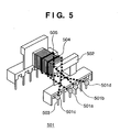
- Fig. 5 shows a conventional push-pull transformer 501 which has a pin terminal 503 to be used to mount the transformer on a printed circuit board.
- primary coils 504 and 505 are wound on a winding core and led out toward a pin terminal 503.
- the end portions are connected to terminals 501a to 501d of the pin terminal 503, thereby forming an output terminal.
- a large current flows to the primary coil of the transformer.
- a flat-type copper wire or a thick copper foil is preferably used as the primary coil.
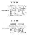
- reference numerals 601 to 604 denote transformers; 605 to 608, input terminals of push-pull circuits; and 609, a through hole.
- a portion indicated by a solid line is a land on the upper surface of the printed circuit board, to which the pin terminal or input terminal of a transformer is connected.
- a portion indicated by a broken line is a land on the lower surface of the printed circuit board.
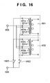
- Figs. 16 and 17 are schematic views showing connection circuits for the transformers and input terminals shown in Figs. 6A and 6B.
- switching elements 1601, 1602, 1701, and 1702 connected to terminals 601c, 602d, 604c, and 604d shown in Figs. 16 and 17 are not illustrated in Figs. 6A and 6B.
- a transformer assembly formed by using a plurality of transformers each formed by winding a primary coil and a secondary coil around a winding core, wherein one terminal and the other terminal of the primary coil are arranged on opposite sides of the winding core, one terminal and the other terminal of the secondary coil are arranged on opposite sides of the winding core, and N transformers in which the coils and the terminals are laid out are arrayed in a lead-out direction of the terminals of the primary coil while M transformers in which the coils and the terminals are laid out are arrayed in a lead-out direction of the terminals of the secondary coil so as to make a line which connects one terminal and the other terminal of the primary coil cross a line which connects one terminal and the other terminal of the secondary coil.
- Fig. 1 is a view showing a transformer assembly 101 according to an embodiment. This assembly is formed by connecting transformers 102 and 103 having the same structure in the lead-out direction of secondary coils through a land 108.
- the transformers 102 and 103 are push-pull circuit transformers.
- Fig. 2 is a circuit diagram of the push-pull transformer.
- Reference numerals 104 to 107 denote primary coils; 102a to 102d and 103a to 103d, terminals of the primary coils; and 102e, 102f, 103e, and 103f, terminals of the secondary coils.
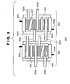
- Fig. 3 is a view showing details of the transformer 102.
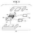
- Fig. 4 is an exploded view of the transformer 102.
- the secondary coil is first connected to the terminal 102e, which is integrated with a bobbin 303, and wound around a bobbin a predetermined number of times such that a desired high voltage can be output. Then, the secondary coil is connected to the terminal 102f arranged on the opposite side of the bobbin.
- the transformers 102 and 103 formed in the above-described way are placed in a line, as shown in Fig. 1, on a printed circuit board.
- the secondary coil terminals 102f and 103e are connected on a land formed on the printed circuit board, thereby forming a transformer assembly.
- the transformers are connected on a printed circuit board.
- the transformer assembly can also be formed by directly connecting the terminals.
- the transformer assembly formed by directly connecting the terminals of the transformers is sealed by an epoxy resin or the like, the transformer assembly can be used as one element.
- the terminals of the transformers, semiconductor elements such as switching elements and diodes, and bear chips may be wired and sealed.
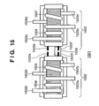
- a transformer assembly 1501 may be formed by leading secondary coil terminals to the same side and connecting terminals 1502f and 1503f through a land 1508.
- the secondary coil terminals are preferably arranged on the opposite sides of the cores.
- a high-efficiency high-step-up low-profile transformer can be formed by using a low-resistance conductor such as a flat-type copper wire which is difficult to process in directions other than the winding direction.
- a high-step-up transformer assembly can easily be formed.
- the terminals can be connected on the same land by the shortest route without using any through hole on the circuit board. Hence, the efficiency of a power conversion apparatus using the transformer assembly can be increased.
- the winding used in the present invention will be described next in detail.
- the winding used in the present invention is not particularly limited. Any winding can be used as long as it has heat resistance, flexibility, oil resistance, solderability, and insulation durability suitable for the use conditions and forming conditions of the transformer.
- a flat-type copper wire is preferably used because of its high space efficiency and low-loss properties for a large current.
- a flat-type copper wire with an insulating material formed on it in advance may be used.
- a bare or tinned copper wire can also be used from the viewpoint of workability and dimensional stability.
- the insulating interlayer taping between the primary coil and the secondary coil can be omitted. This saves the labor and time for transformer formation.
- the transformer can be made more compact. Even when the primary coil or the secondary coil is formed as an air-core coil without using the bobbin as the winding core, the transformer can be made compact.
- the through hole in which a core is to be inserted can be formed by the primary coil or the secondary coil. Hence, a transformer having no bobbin can be formed.
- the number of turns is three for the primary coil and 225 for the secondary coil so that a high-step-up transformer is formed.
- the primary coils are connected in parallel.
- FIG. 3 is a view showing details of the transformer used in this embodiment.
- One end of a class-1 polyurethane electric wire (1UEW) having a diameter of 0.1 mm is soldered to one terminal 102e of a bobbin 303 adaptive to the core.
- the electric wire is wound around the drum portion of the bobbin 303 225 times in multiple layers of proper alignment. Then, the other end of the electric wire is soldered to the other terminal 102f to form a secondary coil 304.
- a flat-type lead wire having a width of 1 mm and a thickness of 0.7 mm is wound in a rectangular shape on the secondary coil while changing the winding direction, thereby forming the primary coils, as shown in Fig. 4.
- Cores 301 and 302 are inserted from both sides into the through hole of the bobbin 303.
- the side surfaces of the cores are double-bonded and fixed by using a polyester adhesive tape No. 31C available from NITTO DENKO, which includes a 55- ⁇ m base and a 25- ⁇ m adhesive sheet, thereby forming the transformers 102 and 103.
- Holes 802 and 803 which receive the transformers are formed in the circuit board in advance.
- the transformers 102 and 103 are inserted and arrayed in the holes.
- the terminals 102e and 103f are arranged on lands 811 and 813, respectively.
- the terminals 102f and 103e are arranged on a land 812.
- the lands and terminals are soldered to form a transformer assembly 101 of this embodiment.
- the terminals 102c, 102d, 103c, and 103d of the transformers 102 and 103 are connected to the separate MOSFETs HAT2164H 805a to 805d available from Hitachi, respectively.
- the terminals 102e and 103f are connected to a diode bridge 806 by a wiring pattern (not shown).
- Fig. 7 is a schematic circuit diagram of a power conversion apparatus 702 using the above-described transformer assembly 101, and a solar power generation apparatus 701 constituted by connecting a solar battery 703 and load 704 to the apparatus 702.
- the outline of the operation of the power conversion apparatus 702 will be described with reference to Fig. 7.
- a DC power input from the solar battery 703 to the input terminal of the power conversion apparatus 702 is smoothed by a capacitor 705 and supplied to switching elements 805 such as MOSFETs through the transformer assembly 101.
- the DC power is converted into an AC power by alternately turning on/off the switching elements 805.
- the AC power input to the transformer assembly 101 is stepped up in accordance with the transformation ratio (3 : 450 in this embodiment) of the transformer assembly 101, rectified by a diode bridge 806, and converted into a DC power.
- the reference wave generation unit 708 generates a reference rectangular wave having a preset frequency and supplies it to the driver 709.
- the driver 709 On the basis of the reference rectangular wave, the driver 709 generates gate driving signals S1 and S2 which alternately turn on/off the switching elements 805, and supplies the gate driving signals S1 and S2 to the gates of the switching elements 805 to turn on/off the switching elements.
- the solar battery 703 used in this embodiment operates at an optimum operating voltage of 1 V and optimum operating current of 10 A under an intensity of 1 sun when a solar simulator is used.
- An output of 150 V and 61 mA could be obtained from the power conversion apparatus by appropriately adjusting the load.
- transformers in which primary coil terminals and secondary coil terminals are arranged on the opposite sides of cores are placed in a line in the horizontal direction and connected. Accordingly, a high-efficiency low-profile high-step-up transformer assembly can be formed. Hence, a high-efficiency low-profile high-step-up power conversion apparatus using the transformer assembly can be provided.
- a transformer assembly used in the second embodiment will be described below. A detailed description of components which are substantially the same as in the above-described first embodiment will be omitted.
- the transformers are placed on a circuit board 1101 of a power conversion apparatus as shown in Fig. 11. Holes 1102 and 1103 which receive the transformers are formed in the circuit board in advance. The transformers 902 and 903 are inserted and arrayed in the holes.
- the transformers 902 and 903 have the same structure. In inserting them in the holes, the orientation of the transformer 903 is reversed to that of the transformer 902 by 180° such that terminals 902c and 902d oppose terminals 903d and 903c, respectively.
- Terminals 902a and 902b are arranged on a land 1104.
- Terminals 903a and 903b are arranged on lands 1113 and 1112, respectively, on which MOSFETs 1105a and 1105b to be connected to the terminals are arranged.
- a power conversion apparatus 1002 is constituted by using the transformer assembly 901 formed by using the circuit board shown in Fig. 11.
- a solar power generation apparatus 1001 shown in Fig. 10 is constituted by connecting a solar battery 1003 and load 1004 to the apparatus 1002.
- the solar battery 1003 a solar battery having three layers of pin structures is used.
- the output voltage per solar battery is larger than that of the solar battery used in the first embodiment. That is, the input voltage to the power conversion apparatus is large.
- the primary coils of the transformers are connected in series.
- the voltage applied to one primary coil of one transformer is about 1/2 the input voltage. Since the use magnetic flux density of the core can be reduced, the number of turns can be decreased to 2/3 that in the first embodiment, and core loss can be decreased.
- transformers in which primary coil terminals and secondary coil terminals are arranged on the opposite sides of cores are placed in a line in the lead-out direction of the primary coil terminals.
- the primary coils having different winding directions and opposing each other between the transformers are connected on the lands 1107 and 1108.
- the secondary coils are connected on the land 1109. Accordingly, a high-efficiency low-profile high-step-up transformer assembly can be formed. Hence, a high-efficiency low-profile high-step-up power conversion apparatus using the transformer assembly can be provided.
- a transformer assembly used in the third embodiment will be described below. A detailed description of components which are substantially the same as in the first or second embodiment will be omitted.
- the number of turns is two for the primary coil and 225 for the secondary coil so that a high-step-up transformer is formed.
- the transformers 1202 to 1205 used in this embodiment are the same as those described in the first embodiment, and a description thereof will be omitted.
- the transformers 1202 to 1205 have the same structure. In inserting them in the holes, the orientation of the transformer 1204 is reversed to that of the transformer 1202 by 180° such that terminals 1202c and 1202d oppose terminals 1204d and 1204c, respectively. In addition, the orientation of the transformer 1205 is reversed to that of the transformer 1203 by 180° such that terminals 1203c and 1203d oppose terminals 1205d and 1205c, respectively.
- the terminals 1202c and 1204d, the terminals 1202d and 1204c, the terminals 1203c and 1205d, and the terminals 1203d and 1205c are arranged on lands 1313 to 1316, respectively.
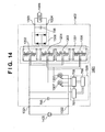
- a power conversion apparatus 1402 is constituted by using the transformer assembly 1301 formed by using the circuit board shown in Fig. 13, and a solar power generation apparatus 1401 is constituted by connecting a solar battery 1403 and load 1404 to the apparatus 1402, as shown in Fig. 14.
- the detailed operations of the circuits are almost the same as in the power conversion apparatus used in the first embodiment, and a description thereof will be omitted.
- the same solar battery as that used in the second embodiment is used as the solar battery 1403.
- the solar battery operates at an optimum operating voltage of 1.4 V and optimum operating current of 10 A under an intensity of 1 sun when a solar simulator is used.
- the voltage is stepped up in accordance with the step-up ratio of the transformer assembly.
- An output of 315 V and 43 mA could be obtained from the power conversion apparatus by appropriately adjusting the load.
- the transformer assembly of the third embodiment two transformers are placed in a line in each of the lead-out direction of the primary coil terminals and the lead-out direction of the secondary coil terminals.
- the primary coil terminals and secondary coil terminals are arranged on the opposite sides of cores.
- the primary coils having different winding directions and opposing each other between the transformer 1202 and the transformer 1204 and between the transformer 1203 and the transformer 1205 are connected on the lands 1313 to 1316.
- the secondary coils of the transformers 1202 and 1203 and those of the transformers 1204 and 1205, which are arrayed in the lead-out direction of the secondary coil terminals, are connected on the lands 1318 and 1319. Accordingly, a high-efficiency low-profile high-step-up transformer assembly can be formed. Hence, a high-efficiency low-profile high-step-up power conversion apparatus using the transformer assembly can be provided.
- a high-step-up transformer assembly can easily be formed.
- the terminals can be connected on the same land by the shortest route without using any through hole on the circuit board. Hence, the efficiency of a power conversion apparatus using the transformer assembly can be increased.
- the transformer assembly can be formed by using transformers with the same structure, the transformers need not individually be managed.
- the thickness of a transformer can be reduced.
- the decrease in efficiency due to the wiring resistance in connection between the terminals of transformers can be prevented.
- a transformer assembly formed by using a plurality of transformers each formed by winding a primary coil and a secondary coil around a winding core, one terminal and the other terminal of the primary coil are arranged on opposite sides of the winding core, one terminal and the other terminal of the secondary coil are arranged on opposite sides of the winding core, and N transformers in which the coils and the terminals are laid out are arrayed in the lead-out direction of the terminals of the primary coil while M transformers in which the coils and the terminals are laid out are arrayed in the lead-out direction of the terminals of the secondary coil so as to make a line which connects one terminal and the other terminal of the primary coil cross a line which connects one terminal and the other terminal of the secondary coil.
Landscapes
- Engineering & Computer Science (AREA)
- Power Engineering (AREA)
- Microelectronics & Electronic Packaging (AREA)
- Coils Or Transformers For Communication (AREA)
- Dc-Dc Converters (AREA)
- Photovoltaic Devices (AREA)
- Coils Of Transformers For General Uses (AREA)
Applications Claiming Priority (2)
| Application Number | Priority Date | Filing Date | Title |
|---|---|---|---|
| JP2003132158 | 2003-05-09 | ||
| JP2003132158A JP2004335886A (ja) | 2003-05-09 | 2003-05-09 | トランス集合体、それを用いた電力変換装置及び太陽光発電装置 |
Publications (2)
| Publication Number | Publication Date |
|---|---|
| EP1475809A2 true EP1475809A2 (fr) | 2004-11-10 |
| EP1475809A3 EP1475809A3 (fr) | 2005-04-20 |
Family
ID=32985684
Family Applications (1)
| Application Number | Title | Priority Date | Filing Date |
|---|---|---|---|
| EP04010787A Withdrawn EP1475809A3 (fr) | 2003-05-09 | 2004-05-06 | Transformateur, dispositif de conversion de puissance et appareil de génération d'énergie solaire l'utilisant |
Country Status (6)
| Country | Link |
|---|---|
| US (1) | US7078997B2 (fr) |
| EP (1) | EP1475809A3 (fr) |
| JP (1) | JP2004335886A (fr) |
| KR (1) | KR20040096783A (fr) |
| CN (1) | CN1551256A (fr) |
| AU (1) | AU2004201798A1 (fr) |
Families Citing this family (30)
| Publication number | Priority date | Publication date | Assignee | Title |
|---|---|---|---|---|
| US6271067B1 (en) * | 1998-02-27 | 2001-08-07 | Micron Technology, Inc. | Methods of forming field effect transistors and field effect transistor circuitry |
| US7612283B2 (en) * | 2002-07-09 | 2009-11-03 | Canon Kabushiki Kaisha | Solar power generation apparatus and its manufacturing method |
| JP2004335885A (ja) | 2003-05-09 | 2004-11-25 | Canon Inc | 電子部品およびその製造方法 |
| JP2008277485A (ja) * | 2007-04-27 | 2008-11-13 | Fuji Electric Device Technology Co Ltd | トランスユニットおよび電力変換装置 |
| JP2009095120A (ja) * | 2007-10-05 | 2009-04-30 | Sanyo Denki Co Ltd | 電力変換器 |
| TW200814105A (en) * | 2007-10-25 | 2008-03-16 | Greatchip Technology Co Ltd | Manufacture adjustable leakage inductance transformer |
| US20100321141A1 (en) * | 2007-10-25 | 2010-12-23 | Chen Hong-Fei | Transformer |
| US20100090789A1 (en) * | 2008-10-14 | 2010-04-15 | Middle Atlantic Products, Inc. | Method, system and transformer for mitigating harmonics |
| TWM371291U (en) * | 2009-03-03 | 2009-12-21 | Delta Electronics Inc | Transformer assembly |
| JP5445789B2 (ja) * | 2009-06-03 | 2014-03-19 | トヨタ自動車株式会社 | 燃料電池システム |
| JP4927142B2 (ja) * | 2009-09-18 | 2012-05-09 | トヨタ自動車株式会社 | 電力変換器 |
| US8779882B2 (en) * | 2009-09-30 | 2014-07-15 | Astec International Limited | Center tapped transformers for isolated power converters |
| CN102194380A (zh) * | 2010-01-20 | 2011-09-21 | 三星电机株式会社 | 平板显示装置以及用于其的共模滤波器 |
| JP5792742B2 (ja) * | 2010-01-23 | 2015-10-14 | ソーラーワット リミテッド | 発電のための太陽光システム |
| US9980396B1 (en) * | 2011-01-18 | 2018-05-22 | Universal Lighting Technologies, Inc. | Low profile magnetic component apparatus and methods |
| CN102158062A (zh) * | 2011-05-20 | 2011-08-17 | 北京国电四维清洁能源技术有限公司 | 光伏并网逆变器 |
| CN102638113B (zh) * | 2012-04-11 | 2014-08-27 | 华中科技大学 | 一种磁耦合谐振装置 |
| US20130293331A1 (en) * | 2012-05-03 | 2013-11-07 | Control Techniques Ltd | Component for clamping choke to chassis |
| US9478351B2 (en) * | 2013-05-24 | 2016-10-25 | Keithley Instruments, Inc. | Isolation transformer for use in isolated DC-to-DC switching power supply |
| JP6553623B2 (ja) * | 2013-09-16 | 2019-07-31 | ザ ボード オブ トラスティーズ オブ ザ レランド スタンフォード ジュニア ユニバーシティー | 電磁エネルギー生成のための多素子カプラ |
| DE102015001011A1 (de) * | 2015-01-28 | 2016-07-28 | ASD Automatic Storage Device GmbH | Gleichstromwandlersystem |
| JP6060206B2 (ja) * | 2015-04-13 | 2017-01-11 | 東邦亜鉛株式会社 | 環状コイル |
| EP3696832B1 (fr) * | 2017-10-12 | 2022-09-07 | Mitsubishi Electric Corporation | Transformateur et dispositif de conversion de puissance |
| CN108880610B (zh) * | 2018-07-19 | 2023-11-10 | 深圳振华富电子有限公司 | 低损耗网络信息传输装置 |
| DE102018218042A1 (de) * | 2018-10-22 | 2020-04-23 | Würth Elektronik eiSos Gmbh & Co. KG | Kern für induktives Bauelement und induktives Bauelement |
| WO2020173865A1 (fr) * | 2019-02-25 | 2020-09-03 | Primozone Production Ab | Générateur d'ozone basse fréquence |
| JP7192593B2 (ja) * | 2019-03-18 | 2022-12-20 | Tdk株式会社 | 電源装置および医療システム |
| JP7251377B2 (ja) * | 2019-07-19 | 2023-04-04 | スミダコーポレーション株式会社 | 磁気結合型リアクトル装置 |
| JP7451469B2 (ja) * | 2021-09-17 | 2024-03-18 | 矢崎総業株式会社 | 結合インダクタ |
| CN113903548B (zh) * | 2021-10-14 | 2024-07-23 | 贵阳顺络迅达电子有限公司 | 一种双通道变压器及其制造方法 |
Family Cites Families (28)
| Publication number | Priority date | Publication date | Assignee | Title |
|---|---|---|---|---|
| US4112481A (en) * | 1977-05-05 | 1978-09-05 | Wescom, Inc. | Miniature multi-impedance transformer module |
| US4665357A (en) * | 1984-04-23 | 1987-05-12 | Edward Herbert | Flat matrix transformer |
| US4814735A (en) * | 1985-06-10 | 1989-03-21 | Williamson Windings Inc. | Magnetic core multiple tap or windings devices |
| DE3536799A1 (de) | 1985-10-16 | 1987-04-16 | Bosch Gmbh Robert | Hf-breitbanduebertragerschaltung |
| WO1989010621A1 (fr) | 1988-04-28 | 1989-11-02 | Fmtt, Inc. | Transformateur matriciel a isolation dielectrique elevee |
| US5093646A (en) * | 1988-04-29 | 1992-03-03 | Fmtt, Inc. | High frequency matrix transformer |
| US4845606A (en) * | 1988-04-29 | 1989-07-04 | Fmtt, Inc. | High frequency matrix transformer |
| JP2547442B2 (ja) | 1988-11-08 | 1996-10-23 | 株式会社新興製作所 | 連続用紙の折りたたみ機構 |
| JPH0648651B2 (ja) | 1990-12-12 | 1994-06-22 | 木嶋無線株式会社 | 電気巻線部品 |
| JPH0729752A (ja) * | 1993-07-09 | 1995-01-31 | Mitsubishi Electric Corp | 内燃機関用点火コイル |
| US5589006A (en) * | 1993-11-30 | 1996-12-31 | Canon Kabushiki Kaisha | Solar battery module and passive solar system using same |
| GB2291736A (en) | 1994-07-16 | 1996-01-31 | Hohner M Ltd | Transducer |
| US5805431A (en) * | 1996-01-17 | 1998-09-08 | Synergy Microwave Corporation | Surface Mountable transformer |
| JPH10270734A (ja) * | 1997-03-27 | 1998-10-09 | Canon Inc | 太陽電池モジュール |
| JPH11150287A (ja) * | 1997-09-10 | 1999-06-02 | Canon Inc | 太陽電池モジュール、太陽電池付き外囲体、太陽電池付き外囲体の設置方法、及び太陽光発電システム |
| JP3792867B2 (ja) * | 1997-11-06 | 2006-07-05 | キヤノン株式会社 | 太陽電池モジュール、太陽電池アレイ及び太陽光発電装置の施工方法 |
| US6114932A (en) * | 1997-12-12 | 2000-09-05 | Telefonaktiebolaget Lm Ericsson | Inductive component and inductive component assembly |
| JP3937654B2 (ja) * | 1998-06-30 | 2007-06-27 | キヤノン株式会社 | 太陽電池モジュール、その設置方法、ならびにそれを用いた太陽光発電装置および屋根 |
| US6137392A (en) * | 1998-10-05 | 2000-10-24 | Herbert; Edward | Transformer for switched mode power supplies and similar applications |
| JP3829572B2 (ja) | 1999-12-15 | 2006-10-04 | 松下電工株式会社 | トランス及びその製造方法 |
| JP2001345472A (ja) * | 2000-03-29 | 2001-12-14 | Canon Inc | 太陽電池モジュールの検査方法、検査装置及び製造方法、太陽光発電システムの点検方法及び点検装置、並びに絶縁抵抗測定器及び耐電圧試験器 |
| JP2002111038A (ja) * | 2000-09-29 | 2002-04-12 | Canon Inc | 太陽電池モジュールおよびその製造方法、並びに、発電装置 |
| JP2003052185A (ja) * | 2001-05-30 | 2003-02-21 | Canon Inc | 電力変換器およびそれを用いる光起電力素子モジュール並びに発電装置 |
| US6927667B1 (en) * | 2001-11-01 | 2005-08-09 | Tyco Electronics Power Systems, Inc. | Magnetic device having a springable winding |
| US6734775B2 (en) * | 2002-04-29 | 2004-05-11 | Yu-Lin Chung | Transformer structure |
| JP2003333861A (ja) * | 2002-05-10 | 2003-11-21 | Canon Inc | 電源装置およびその設計方法、並びに、発電装置 |
| JP2004207700A (ja) * | 2002-12-11 | 2004-07-22 | Canon Inc | 電子部品およびその製造方法 |
| EP1431987A3 (fr) * | 2002-12-19 | 2004-08-11 | Canon Kabushiki Kaisha | Dispositif électrique, transformateur ou inductance, et procédé de fabrication d'un dispositif électrique |
-
2003
- 2003-05-09 JP JP2003132158A patent/JP2004335886A/ja not_active Withdrawn
-
2004
- 2004-04-29 AU AU2004201798A patent/AU2004201798A1/en not_active Abandoned
- 2004-04-30 US US10/835,009 patent/US7078997B2/en not_active Expired - Fee Related
- 2004-05-06 EP EP04010787A patent/EP1475809A3/fr not_active Withdrawn
- 2004-05-08 KR KR1020040032466A patent/KR20040096783A/ko not_active Ceased
- 2004-05-09 CN CNA2004100421420A patent/CN1551256A/zh active Pending
Also Published As
| Publication number | Publication date |
|---|---|
| JP2004335886A (ja) | 2004-11-25 |
| US20040222873A1 (en) | 2004-11-11 |
| EP1475809A3 (fr) | 2005-04-20 |
| KR20040096783A (ko) | 2004-11-17 |
| AU2004201798A1 (en) | 2004-11-25 |
| US7078997B2 (en) | 2006-07-18 |
| CN1551256A (zh) | 2004-12-01 |
Similar Documents
| Publication | Publication Date | Title |
|---|---|---|
| EP1475809A2 (fr) | Transformateur, dispositif de conversion de puissance et appareil de génération d'énergie solaire l'utilisant | |
| US10325714B2 (en) | Integrated magnetic component and switched mode power converter | |
| CN105529156B (zh) | 嵌入式磁性构件变压器装置 | |
| EP0531687A2 (fr) | Convertisseur à découpage à haute fréquence de faible cout et méthode de fabrication dudit convertisseur | |
| US9847166B2 (en) | Embedded magnetic component transformer device | |
| EP1128402A1 (fr) | Dispositif magnétique utilisant une structure d'enroulement dans plusieurs circuits imprimés et son procédé de fabrication | |
| JP2000260639A (ja) | コイル装置およびこれを用いたスイッチング電源装置 | |
| US9013259B2 (en) | Powder core material coupled inductors and associated methods | |
| GB2531348A (en) | Embedded magnetic component transformer device | |
| CN103348577A (zh) | 绝缘型开关电源装置 | |
| CN107527727A (zh) | 一种电感和电源转换电路 | |
| JP2009170804A (ja) | 点灯装置 | |
| KR20010033225A (ko) | 스윗치 모드 전력공급용, 특히 스터드용접장치용 전원변압기 | |
| KR20040054586A (ko) | 전자부품, 트랜스, 인덕터 및 전자부품의 제조방법 | |
| KR102886937B1 (ko) | 권선 코일 및 패턴 코일을 이용한 자성부품 | |
| CN113555196B (zh) | 变压器模块及功率模块 | |
| CN104051143B (zh) | 具有平面初级绕组的变换器 | |
| JP2004022721A (ja) | トランスおよびその製造方法、電力変換装置、並びに、発電装置 | |
| CN114613580A (zh) | 一种电源适配器 | |
| CN119694733B (zh) | 一种llc变压器 | |
| JP2000299233A (ja) | 電源用トランス | |
| EP4583131A1 (fr) | Transformateur et convertisseur résonant llc le comprenant | |
| US20230187119A1 (en) | Embedded magnetic component transformer device | |
| JP2004335884A (ja) | トランス及び該トランスを用いた装置、並びにトランスの製造方法 | |
| KR100497308B1 (ko) | 인쇄회로기판 매립형 인덕터 및 그 제조 방법 |
Legal Events
| Date | Code | Title | Description |
|---|---|---|---|
| PUAI | Public reference made under article 153(3) epc to a published international application that has entered the european phase |
Free format text: ORIGINAL CODE: 0009012 |
|
| AK | Designated contracting states |
Kind code of ref document: A2 Designated state(s): AT BE BG CH CY CZ DE DK EE ES FI FR GB GR HU IE IT LI LU MC NL PL PT RO SE SI SK TR |
|
| AX | Request for extension of the european patent |
Extension state: AL HR LT LV MK |
|
| PUAL | Search report despatched |
Free format text: ORIGINAL CODE: 0009013 |
|
| AK | Designated contracting states |
Kind code of ref document: A3 Designated state(s): AT BE BG CH CY CZ DE DK EE ES FI FR GB GR HU IE IT LI LU MC NL PL PT RO SE SI SK TR |
|
| AX | Request for extension of the european patent |
Extension state: AL HR LT LV MK |
|
| RIC1 | Information provided on ipc code assigned before grant |
Ipc: 7H 01F 30/06 B Ipc: 7H 01F 38/00 B Ipc: 7H 01F 27/28 A |
|
| 17P | Request for examination filed |
Effective date: 20050901 |
|
| AKX | Designation fees paid |
Designated state(s): AT BE BG CH CY CZ DE DK EE ES FI FR GB GR HU IE IT LI LU MC NL PL PT RO SE SI SK TR |
|
| STAA | Information on the status of an ep patent application or granted ep patent |
Free format text: STATUS: THE APPLICATION HAS BEEN WITHDRAWN |
|
| 18W | Application withdrawn |
Effective date: 20060504 |