EP1477248A2 - Verfahren zur Herstellung eines Hohlkörpers als Halbzeug für einen Tiegel oder eine Giesswalze - Google Patents
Verfahren zur Herstellung eines Hohlkörpers als Halbzeug für einen Tiegel oder eine Giesswalze Download PDFInfo
- Publication number
- EP1477248A2 EP1477248A2 EP04007496A EP04007496A EP1477248A2 EP 1477248 A2 EP1477248 A2 EP 1477248A2 EP 04007496 A EP04007496 A EP 04007496A EP 04007496 A EP04007496 A EP 04007496A EP 1477248 A2 EP1477248 A2 EP 1477248A2
- Authority
- EP
- European Patent Office
- Prior art keywords
- block
- hollow body
- mandrel
- crucible
- expanded
- Prior art date
- Legal status (The legal status is an assumption and is not a legal conclusion. Google has not performed a legal analysis and makes no representation as to the accuracy of the status listed.)
- Granted
Links
Images

Classifications
-
- B—PERFORMING OPERATIONS; TRANSPORTING
- B21—MECHANICAL METAL-WORKING WITHOUT ESSENTIALLY REMOVING MATERIAL; PUNCHING METAL
- B21K—MAKING FORGED OR PRESSED METAL PRODUCTS, e.g. HORSE-SHOES, RIVETS, BOLTS OR WHEELS
- B21K21/00—Making hollow articles not covered by a single preceding sub-group
- B21K21/06—Shaping thick-walled hollow articles, e.g. projectiles
-
- B—PERFORMING OPERATIONS; TRANSPORTING
- B21—MECHANICAL METAL-WORKING WITHOUT ESSENTIALLY REMOVING MATERIAL; PUNCHING METAL
- B21J—FORGING; HAMMERING; PRESSING METAL; RIVETING; FORGE FURNACES
- B21J5/00—Methods for forging, hammering, or pressing; Special equipment or accessories therefor
- B21J5/06—Methods for forging, hammering, or pressing; Special equipment or accessories therefor for performing particular operations
- B21J5/08—Upsetting
-
- B—PERFORMING OPERATIONS; TRANSPORTING
- B21—MECHANICAL METAL-WORKING WITHOUT ESSENTIALLY REMOVING MATERIAL; PUNCHING METAL
- B21J—FORGING; HAMMERING; PRESSING METAL; RIVETING; FORGE FURNACES
- B21J5/00—Methods for forging, hammering, or pressing; Special equipment or accessories therefor
- B21J5/06—Methods for forging, hammering, or pressing; Special equipment or accessories therefor for performing particular operations
- B21J5/10—Piercing billets
Definitions
- the invention relates to a method for producing a cylindrical hollow body made of copper or a copper alloy as a semi-finished product for a crucible or a Casting roll according to the features in the preamble of claim 1.
- a common method for producing a cylindrical hollow body as a semi-finished product for a crucible or a casting roll the steps of casting-punching-forging are used together.
- a continuously cast block in the longitudinal direction compressed The maximum is so that the block does not buckle when compressed Ratio of its length to its diameter about 3: 1.
- the compressed block will then the aid of a piercing mandrel over its entire length as seen in the direction of the upset Extension punched.
- the perforated block is then heated again and in this second heat Forging expanded over a mandrel.
- the expanded block is then usually made into one by open-die forging Formed hollow body with or without flange, depending on whether from this In the end, a crucible or a casting roller is to be manufactured.
- a crucible or a casting roller is to be manufactured.
- the invention is based on the object Process for producing a cylindrical hollow body made of copper or a To create copper alloy as a semi-finished product for a crucible or a casting roller, the more economical application with improved material properties guaranteed.
- the hollow body produced in this way can then be turned into a crucible or a conventional manner Casting roller can be redesigned further.
- the invention therefore creates the conditions for the Total degree of deformation and the homogeneity of the deformation due to Process steps punching the cylindrical block with the following Drawing presses can be significantly improved. Due to the higher dimensional accuracy there are also significantly smaller additions of lost material. The Efficiency is significantly increased.
- cylindrical hollow bodies as semi-finished products a crucible or a casting roll by rounding and longitudinal seam welding of To manufacture sheets.
- the invention has the additional advantage that the material properties over the entire scope of the Hollow body are homogeneous.
- the combination of expanding the block and stretching the Crystal orientation of the hollow body to be manufactured can be influenced so that a Orientation of the grain structure in the longitudinal or transverse direction arises. So it can Grain orientation and thus the strength through this way of Main direction of stress can be adjusted. Accordingly, in particular better service life can be expected from casting rolls made from hollow bodies.
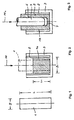
- FIG. 1 is a cylindrical block made of SF-Cu, CuAg, CuNi or one precipitation-hardening Cu alloy. Block 1 is continuously cast. The ratio of the length L to the diameter D is up to about 6: 1.
- the block 1 according to FIG. 1 is divided into a corresponding to the representation of FIG Die 2 used, which is located in a receptacle 3.
- Block 1 is in broken lines shown.
- the Die 2 prevents block 1 from buckling during upsetting.
- the compressed block 1 a Center punch 4 pressed in according to arrow PF1 and block 1 a perforated.
- the material of the perforated block 1 b then rises between the inner wall 5 of the die 2 and the surface 6 of the piercing mandrel 4 upwards in a hollow cylinder.
- the Punching in the direction of arrow PF1 is carried out in such a way that on the punched block 1 b a bottom 7 remains.
- the perforated block 1 b is then used in accordance with the illustration in FIG an expanding mandrel 8 which is moved in the direction of the arrow PF2, wherein its inner diameter changes from ID to ID1 and its outer diameter changes from AD Increase AD1.
- the block 1b to be expanded is based on one Abutment plate 9 from.
- the stretching can be done so that the expanded block 1 c is not complete is moved by the drawing die 11, so that then at the free end 13 of the Hollow body 12 a collar 14 is formed.
- This collar 14 can be used to weld a Flange are used.
Landscapes
- Engineering & Computer Science (AREA)
- Mechanical Engineering (AREA)
- Forging (AREA)
- Rolls And Other Rotary Bodies (AREA)
- Shaping By String And By Release Of Stress In Plastics And The Like (AREA)
- Cylinder Crankcases Of Internal Combustion Engines (AREA)
- Continuous Casting (AREA)
Abstract
Description
- Figur 1
- in der Seitenansicht einen gegossenen zylindrischen Block;
- Figur 2
- im schematischen vertikalen Querschnitt eine Aufnahme mit Matrize für den Block der Figur 1;
- Figur 3
- im schematischen vertikalen Querschnitt die Aufnahme mit Matrize beim Lochen des Blocks;
- Figur 4
- im schematischen vertikalen Längsschnitt das Aufweiten des gelochten Blocks und
- Figur 5
- im schematischen vertikalen Längsschnitt das Abstrecken des aufgeweiteten Blocks.
- 1 -
- Block
- 1a -
- gestauchter Block
- 1b -
- gelochter Block
- 1c -
- aufgeweiteter Block
- 2 -
- Matrize
- 3 -
- Aufnahme f. 2
- 4 -
- Lochdorn
- 5 -
- Innenwand v. 2
- 6 -
- Oberfläche v. 4
- 7 -
- Boden
- 8 -
- Aufweitdorn
- 9 -
- Widerlagerplatte
- 10 -
- Ziehdorn
- 11 -
- Matrize
- 12 -
- Hohlkörper
- 13 -
- freies Ende v. 12
- 14 -
- Bund an 13
- AD -
- Außendurchmesser v. 1b
- AD1 -
- Außendurchmesser v. 1c
- D -
- Durchmesser v. 1
- D1 -
- Durchmesser v. 1a
- ID -
- Innendurchmesser v. 1b
- ID1 -
- Innendurchmesser v. 1c
- L -
- Länge v. 1
- L1 -
- Länge v. 1a
- PF -
- Pfeil
- PF1 -
- Pfeil
- PF2 -
- Pfeil
- PF3 -
- Pfeil
Claims (3)
- Verfahren zur Herstellung eines zylindrischen Hohlkörpers (12) aus Kupfer oder einer Kupferlegierung als Halbzeug für einen Tiegel oder eine Gießwalze, bei welchem zunächst ein zylindrischer Block (1) gegossen, dieser Block (1) dann in erwärmten Zustand in Längsrichtung gestaucht, anschließend gelocht und letztlich unter Einsatz eines Dorns (10) zum Hohlkörper (12) umgeformt wird, dadurch gekennzeichnet, dass sowohl das Stauchen als auch das anschließende Lochen unter radialer Abstützung des Blocks (1) durchgeführt werden, wobei am gelochten Block (1b) ein Boden (7) belassen wird, und dass dann der gelochte Block (1b) im Innendurchmesser (ID) und Außendurchmesser (AD) mittels eines Dorns (8) aufgeweitet und letztlich der so aufgeweitete Block (1c) über einen Dorn (10) durch umfangsseitiges Abstrecken zum Hohlkörper (12) umgeformt werden.
- Verfahren nach Patentanspruch 1, dadurch gekennzeichnet, dass alle Umformschritte in einer Wärme durchgeführt werden.
- Verfahren nach Patentanspruch 1 oder 2, dadurch gekennzeichnet, dass beim Abstrecken des aufgeweiteten Blocks (1c) ein Bund (14) am Hohlkörper (12) erzeugt wird.
Applications Claiming Priority (2)
| Application Number | Priority Date | Filing Date | Title |
|---|---|---|---|
| DE10321566 | 2003-05-14 | ||
| DE10321566A DE10321566A1 (de) | 2003-05-14 | 2003-05-14 | Verfahren zur Herstellung eines Hohlkörpers als Halbzeug für einen Tiegel oder eine Gießwalze |
Publications (3)
| Publication Number | Publication Date |
|---|---|
| EP1477248A2 true EP1477248A2 (de) | 2004-11-17 |
| EP1477248A3 EP1477248A3 (de) | 2005-01-05 |
| EP1477248B1 EP1477248B1 (de) | 2006-08-23 |
Family
ID=33016381
Family Applications (1)
| Application Number | Title | Priority Date | Filing Date |
|---|---|---|---|
| EP04007496A Expired - Lifetime EP1477248B1 (de) | 2003-05-14 | 2004-03-27 | Verfahren zur Herstellung eines Hohlkörpers als Halbzeug für einen Tiegel oder eine Giesswalze |
Country Status (6)
| Country | Link |
|---|---|
| EP (1) | EP1477248B1 (de) |
| AT (1) | ATE337116T1 (de) |
| DE (2) | DE10321566A1 (de) |
| DK (1) | DK1477248T3 (de) |
| ES (1) | ES2268522T3 (de) |
| PT (1) | PT1477248E (de) |
Cited By (3)
| Publication number | Priority date | Publication date | Assignee | Title |
|---|---|---|---|---|
| WO2007134577A1 (de) * | 2006-05-22 | 2007-11-29 | Sandvik Mining And Construction Supply Gmbh | Förderrolle |
| CN100446889C (zh) * | 2007-04-12 | 2008-12-31 | 林昌绪 | 利用冷镦机加工金属盲管零件的加工方法 |
| US20150050513A1 (en) * | 2011-12-30 | 2015-02-19 | Babasaheb Neelkanth Kalyani | Method For Manufacturing Hollow Shafts |
Families Citing this family (3)
| Publication number | Priority date | Publication date | Assignee | Title |
|---|---|---|---|---|
| RU2605875C1 (ru) * | 2015-07-13 | 2016-12-27 | Виталий Вениаминович Девятов | Способ изготовления длинномерных полых изделий |
| RU2699425C1 (ru) * | 2018-07-30 | 2019-09-05 | Федеральное государственное бюджетное образовательное учреждение высшего образования "Кубанский государственный технологический университет" (ФГБОУ ВО "КубГТУ") | Способ изготовления полой цилиндрической заготовки |
| DE102024109118A1 (de) * | 2024-03-28 | 2025-10-02 | Sms Group Gmbh | Verfahren und Vorrichtung zur Herstellung von Hülsen |
Family Cites Families (7)
| Publication number | Priority date | Publication date | Assignee | Title |
|---|---|---|---|---|
| DE2425501A1 (de) * | 1974-05-27 | 1975-12-11 | Kabel Metallwerke Ghh | Verfahren und vorrichtung zum napffliesspressen von dickwandigen hohlkoerpern mit boden |
| US4059003A (en) * | 1974-10-29 | 1977-11-22 | Moore Charles H | Process for producing heavy-duty high-pressure ferrous metal cup-shaped products having a cylindrical barrel |
| DE2817415A1 (de) * | 1978-04-18 | 1979-10-25 | Mannesmann Ag | Verfahren und vorrichtung zum warmfliesspressen von lochstuecken mit bodenstueck aus rundstranggussbloecken |
| JPS6049825A (ja) * | 1983-08-31 | 1985-03-19 | Komatsu Ltd | 鍛造によるせん孔方法 |
| DE19852537C2 (de) * | 1998-11-05 | 2003-01-09 | Mannesmann Ag | Ziehpreßverfahren zur Herstellung eines nahtlosen Hohlkörpers mit Boden oder eines nahtlosen Rohres |
| EP1193720B1 (de) * | 2000-04-25 | 2017-01-11 | Japan Casting & Forging Corporation | Rohling für einen behälter zum einschluss von radioaktiven stoffen und verfahren zu seiner herstellung |
| DE10108861B4 (de) * | 2001-02-15 | 2005-02-03 | V&M Deutschland Gmbh | Einrichtung zur Herstellung eines nahtlosen Hohlkörpers mit Boden oder eines nahtlosen Rohres aus Stahl |
-
2003
- 2003-05-14 DE DE10321566A patent/DE10321566A1/de not_active Withdrawn
-
2004
- 2004-03-27 PT PT04007496T patent/PT1477248E/pt unknown
- 2004-03-27 EP EP04007496A patent/EP1477248B1/de not_active Expired - Lifetime
- 2004-03-27 DK DK04007496T patent/DK1477248T3/da active
- 2004-03-27 ES ES04007496T patent/ES2268522T3/es not_active Expired - Lifetime
- 2004-03-27 DE DE502004001238T patent/DE502004001238D1/de not_active Expired - Fee Related
- 2004-03-27 AT AT04007496T patent/ATE337116T1/de not_active IP Right Cessation
Cited By (5)
| Publication number | Priority date | Publication date | Assignee | Title |
|---|---|---|---|---|
| WO2007134577A1 (de) * | 2006-05-22 | 2007-11-29 | Sandvik Mining And Construction Supply Gmbh | Förderrolle |
| EA014477B1 (ru) * | 2006-05-22 | 2010-12-30 | Сандвик Майнинг Энд Констракшн Сапплай Гмбх | Конвейерный ролик |
| CN100446889C (zh) * | 2007-04-12 | 2008-12-31 | 林昌绪 | 利用冷镦机加工金属盲管零件的加工方法 |
| US20150050513A1 (en) * | 2011-12-30 | 2015-02-19 | Babasaheb Neelkanth Kalyani | Method For Manufacturing Hollow Shafts |
| US9446445B2 (en) * | 2011-12-30 | 2016-09-20 | Bharat Forge Ltd. | Method for manufacturing hollow shafts |
Also Published As
| Publication number | Publication date |
|---|---|
| ATE337116T1 (de) | 2006-09-15 |
| EP1477248A3 (de) | 2005-01-05 |
| DE10321566A1 (de) | 2004-12-02 |
| DE502004001238D1 (de) | 2006-10-05 |
| EP1477248B1 (de) | 2006-08-23 |
| DK1477248T3 (da) | 2007-01-02 |
| ES2268522T3 (es) | 2007-03-16 |
| PT1477248E (pt) | 2006-12-29 |
Similar Documents
| Publication | Publication Date | Title |
|---|---|---|
| DE3742869B4 (de) | Rohrförmige Stabilisatorstange und Verfahren zu deren Herstellung | |
| DE69817947T2 (de) | Vorrichtung zum Hydroformen eines Rohres aus Metall | |
| DE3788305T2 (de) | Verfahren zum Herstellen von Faltenbälgen mit elliptscher, eiformiger, aus zwei gleichen mit parallelen Geraden verbundenen Halbkreisen geformter, nicht kreisförmig ringförmiger oder abgerundet polygonaler Querschnittsform. | |
| DE60318678T2 (de) | Tailor welded blank zum Innenhochdruckumformen und Verfahren zum Herstellen und zum Innenhochdruckumformen eines solchen Blanks | |
| WO2006024281A1 (de) | Verfahren zum herstellen von radnaben-rohlingen auf einer druckumformmaschine | |
| DE102019104222A1 (de) | Gestanzten Komponente mit verbesserter Verformbarkeit | |
| DE102017102356B3 (de) | Verfahren und Vorrichtung zum Herstellen eines Kragens an einem Werkstück | |
| EP1477248B1 (de) | Verfahren zur Herstellung eines Hohlkörpers als Halbzeug für einen Tiegel oder eine Giesswalze | |
| DE102021102745A1 (de) | Verfahren zur Herstellung eines Tanks zur Speicherung verdichteter Fluide | |
| DE102020132822B4 (de) | Verfahren zur Herstellung eines inneren Anschlags in einem Rohrbauteil | |
| EP1027177B1 (de) | Verfahren zum herstellen von nickel-titan-hohlprofilen | |
| DE102015108768A1 (de) | Verfahren und Vorrichtung zur Erzielung von großen Kragenlängen | |
| EP3253509B1 (de) | Verfahren und vorrichtung zum auskragen eines werkstücks | |
| EP1654080A1 (de) | Verfahren zum innenhochdruckumformen von konischen rohren aus metall | |
| EP1464566B1 (de) | Verfahren zur Herstellung eines Hohlformteils mit geschlossenem Querschnitt und einer Verstärkung | |
| DE102015206461A1 (de) | Verfahren zur Umformung eines rohrförmigen Strukturbauteils für Kraftfahrzeugsitze | |
| WO2016119940A1 (de) | Verfahren und vorrichtung zur herstellung eines kragens an einem werkstück | |
| DE10027703A1 (de) | Verfahren und Vorrichtung zum Umformen, insbesondere Fließpressen eines metallischen Werkstücks | |
| DE69322965T2 (de) | Verfahren zur herstellung von rohrförmigen elementen mit integralen äusserlichen vorsprüngen | |
| DE102018100413B3 (de) | Verfahren und Vorrichtung zum Herstellen von hohlen, innengekühlten Ventilen | |
| DE102016103271A1 (de) | Verfahren zum Herstellen eines Kragens an einem Werkstück mittels eines Vorkragens | |
| DE102015122656A1 (de) | Verfahren zum auspressen von werkteilen vom typ hülse sowie vorrichtung zu dessen umsetzung | |
| DE102016114934B3 (de) | Verfahren und Vorrichtung zur Herstellung eines runden Hohlprofils | |
| DE102005036419B4 (de) | Vorrichtung zur Herstellung ausgebauchter Hohlprofile, insbesondere von Gasgeneratorgehäusen für Airbageinrichtungen | |
| WO2011117147A1 (de) | Verfahren zur herstellung von lamellen für wärmeaustauscher und vorrichtung zur durchführung dieses verfahrens |
Legal Events
| Date | Code | Title | Description |
|---|---|---|---|
| PUAI | Public reference made under article 153(3) epc to a published international application that has entered the european phase |
Free format text: ORIGINAL CODE: 0009012 |
|
| AK | Designated contracting states |
Kind code of ref document: A2 Designated state(s): AT BE BG CH CY CZ DE DK EE ES FI FR GB GR HU IE IT LI LU MC NL PL PT RO SE SI SK TR |
|
| AX | Request for extension of the european patent |
Extension state: AL LT LV MK |
|
| PUAL | Search report despatched |
Free format text: ORIGINAL CODE: 0009013 |
|
| AK | Designated contracting states |
Kind code of ref document: A3 Designated state(s): AT BE BG CH CY CZ DE DK EE ES FI FR GB GR HU IE IT LI LU MC NL PL PT RO SE SI SK TR |
|
| AX | Request for extension of the european patent |
Extension state: AL LT LV MK |
|
| RIC1 | Information provided on ipc code assigned before grant |
Ipc: 7B 21J 5/08 A Ipc: 7B 21J 5/10 B Ipc: 7B 21K 21/06 B |
|
| AKX | Designation fees paid | ||
| REG | Reference to a national code |
Ref country code: DE Ref legal event code: 8566 |
|
| 17P | Request for examination filed |
Effective date: 20051007 |
|
| RBV | Designated contracting states (corrected) |
Designated state(s): AT BE BG CH CY CZ DE DK EE ES FI FR GB GR HU IE IT LI LU MC NL PL PT RO SE SI SK TR |
|
| GRAP | Despatch of communication of intention to grant a patent |
Free format text: ORIGINAL CODE: EPIDOSNIGR1 |
|
| GRAS | Grant fee paid |
Free format text: ORIGINAL CODE: EPIDOSNIGR3 |
|
| GRAA | (expected) grant |
Free format text: ORIGINAL CODE: 0009210 |
|
| AK | Designated contracting states |
Kind code of ref document: B1 Designated state(s): AT BE BG CH CY CZ DE DK EE ES FI FR GB GR HU IE IT LI LU MC NL PL PT RO SE SI SK TR |
|
| PG25 | Lapsed in a contracting state [announced via postgrant information from national office to epo] |
Ref country code: CZ Free format text: LAPSE BECAUSE OF FAILURE TO SUBMIT A TRANSLATION OF THE DESCRIPTION OR TO PAY THE FEE WITHIN THE PRESCRIBED TIME-LIMIT Effective date: 20060823 Ref country code: SI Free format text: LAPSE BECAUSE OF FAILURE TO SUBMIT A TRANSLATION OF THE DESCRIPTION OR TO PAY THE FEE WITHIN THE PRESCRIBED TIME-LIMIT Effective date: 20060823 Ref country code: IE Free format text: LAPSE BECAUSE OF FAILURE TO SUBMIT A TRANSLATION OF THE DESCRIPTION OR TO PAY THE FEE WITHIN THE PRESCRIBED TIME-LIMIT Effective date: 20060823 Ref country code: PL Free format text: LAPSE BECAUSE OF FAILURE TO SUBMIT A TRANSLATION OF THE DESCRIPTION OR TO PAY THE FEE WITHIN THE PRESCRIBED TIME-LIMIT Effective date: 20060823 Ref country code: RO Free format text: LAPSE BECAUSE OF FAILURE TO SUBMIT A TRANSLATION OF THE DESCRIPTION OR TO PAY THE FEE WITHIN THE PRESCRIBED TIME-LIMIT Effective date: 20060823 Ref country code: SK Free format text: LAPSE BECAUSE OF FAILURE TO SUBMIT A TRANSLATION OF THE DESCRIPTION OR TO PAY THE FEE WITHIN THE PRESCRIBED TIME-LIMIT Effective date: 20060823 Ref country code: IT Free format text: LAPSE BECAUSE OF FAILURE TO SUBMIT A TRANSLATION OF THE DESCRIPTION OR TO PAY THE FEE WITHIN THE PRESCRIBED TIME-LIMIT;WARNING: LAPSES OF ITALIAN PATENTS WITH EFFECTIVE DATE BEFORE 2007 MAY HAVE OCCURRED AT ANY TIME BEFORE 2007. THE CORRECT EFFECTIVE DATE MAY BE DIFFERENT FROM THE ONE RECORDED. Effective date: 20060823 |
|
| REG | Reference to a national code |
Ref country code: GB Ref legal event code: FG4D Free format text: NOT ENGLISH |
|
| REG | Reference to a national code |
Ref country code: CH Ref legal event code: EP |
|
| REG | Reference to a national code |
Ref country code: IE Ref legal event code: FG4D Free format text: LANGUAGE OF EP DOCUMENT: GERMAN |
|
| REF | Corresponds to: |
Ref document number: 502004001238 Country of ref document: DE Date of ref document: 20061005 Kind code of ref document: P |
|
| GBT | Gb: translation of ep patent filed (gb section 77(6)(a)/1977) |
Effective date: 20060921 |
|
| REG | Reference to a national code |
Ref country code: CH Ref legal event code: NV Representative=s name: PA ALDO ROEMPLER |
|
| REG | Reference to a national code |
Ref country code: SE Ref legal event code: TRGR |
|
| PG25 | Lapsed in a contracting state [announced via postgrant information from national office to epo] |
Ref country code: BG Free format text: LAPSE BECAUSE OF FAILURE TO SUBMIT A TRANSLATION OF THE DESCRIPTION OR TO PAY THE FEE WITHIN THE PRESCRIBED TIME-LIMIT Effective date: 20061123 |
|
| REG | Reference to a national code |
Ref country code: GR Ref legal event code: EP Ref document number: 20060403793 Country of ref document: GR |
|
| REG | Reference to a national code |
Ref country code: PT Ref legal event code: SC4A Free format text: AVAILABILITY OF NATIONAL TRANSLATION Effective date: 20061106 |
|
| REG | Reference to a national code |
Ref country code: DK Ref legal event code: T3 |
|
| ET | Fr: translation filed | ||
| REG | Reference to a national code |
Ref country code: ES Ref legal event code: FG2A Ref document number: 2268522 Country of ref document: ES Kind code of ref document: T3 |
|
| REG | Reference to a national code |
Ref country code: IE Ref legal event code: FD4D |
|
| PGFP | Annual fee paid to national office [announced via postgrant information from national office to epo] |
Ref country code: DE Payment date: 20070322 Year of fee payment: 4 |
|
| PLBE | No opposition filed within time limit |
Free format text: ORIGINAL CODE: 0009261 |
|
| STAA | Information on the status of an ep patent application or granted ep patent |
Free format text: STATUS: NO OPPOSITION FILED WITHIN TIME LIMIT |
|
| REG | Reference to a national code |
Ref country code: CH Ref legal event code: PFA Owner name: KME GERMANY AG Free format text: KM EUROPA METAL AKTIENGESELLSCHAFT#POSTFACH 3320#D-49023 OSNABRUECK (DE) -TRANSFER TO- KME GERMANY AG#KLOSTERSTRASSE 29#49074 OSNABRUECK (DE) |
|
| 26N | No opposition filed |
Effective date: 20070524 |
|
| PG25 | Lapsed in a contracting state [announced via postgrant information from national office to epo] |
Ref country code: MC Free format text: LAPSE BECAUSE OF NON-PAYMENT OF DUE FEES Effective date: 20070331 |
|
| PGFP | Annual fee paid to national office [announced via postgrant information from national office to epo] |
Ref country code: CH Payment date: 20080313 Year of fee payment: 5 Ref country code: DK Payment date: 20080314 Year of fee payment: 5 |
|
| PGFP | Annual fee paid to national office [announced via postgrant information from national office to epo] |
Ref country code: FI Payment date: 20080314 Year of fee payment: 5 Ref country code: IT Payment date: 20080321 Year of fee payment: 5 Ref country code: NL Payment date: 20080303 Year of fee payment: 5 Ref country code: PT Payment date: 20080312 Year of fee payment: 5 Ref country code: SE Payment date: 20080306 Year of fee payment: 5 |
|
| PGFP | Annual fee paid to national office [announced via postgrant information from national office to epo] |
Ref country code: AT Payment date: 20080313 Year of fee payment: 5 |
|
| PG25 | Lapsed in a contracting state [announced via postgrant information from national office to epo] |
Ref country code: EE Free format text: LAPSE BECAUSE OF FAILURE TO SUBMIT A TRANSLATION OF THE DESCRIPTION OR TO PAY THE FEE WITHIN THE PRESCRIBED TIME-LIMIT Effective date: 20060823 |
|
| PGFP | Annual fee paid to national office [announced via postgrant information from national office to epo] |
Ref country code: ES Payment date: 20080418 Year of fee payment: 5 Ref country code: FR Payment date: 20080311 Year of fee payment: 5 |
|
| REG | Reference to a national code |
Ref country code: CH Ref legal event code: PCAR Free format text: ALDO ROEMPLER PATENTANWALT;BRENDENWEG 11 POSTFACH 154;9424 RHEINECK (CH) |
|
| PGFP | Annual fee paid to national office [announced via postgrant information from national office to epo] |
Ref country code: BE Payment date: 20080522 Year of fee payment: 5 |
|
| GBPC | Gb: european patent ceased through non-payment of renewal fee |
Effective date: 20080327 |
|
| PG25 | Lapsed in a contracting state [announced via postgrant information from national office to epo] |
Ref country code: DE Free format text: LAPSE BECAUSE OF NON-PAYMENT OF DUE FEES Effective date: 20081001 |
|
| PGFP | Annual fee paid to national office [announced via postgrant information from national office to epo] |
Ref country code: GR Payment date: 20080215 Year of fee payment: 5 |
|
| PG25 | Lapsed in a contracting state [announced via postgrant information from national office to epo] |
Ref country code: GB Free format text: LAPSE BECAUSE OF NON-PAYMENT OF DUE FEES Effective date: 20080327 |
|
| PG25 | Lapsed in a contracting state [announced via postgrant information from national office to epo] |
Ref country code: CY Free format text: LAPSE BECAUSE OF FAILURE TO SUBMIT A TRANSLATION OF THE DESCRIPTION OR TO PAY THE FEE WITHIN THE PRESCRIBED TIME-LIMIT Effective date: 20060823 Ref country code: LU Free format text: LAPSE BECAUSE OF NON-PAYMENT OF DUE FEES Effective date: 20070327 |
|
| BERE | Be: lapsed |
Owner name: *KM EUROPA METAL A.G. Effective date: 20090331 |
|
| PG25 | Lapsed in a contracting state [announced via postgrant information from national office to epo] |
Ref country code: HU Free format text: LAPSE BECAUSE OF FAILURE TO SUBMIT A TRANSLATION OF THE DESCRIPTION OR TO PAY THE FEE WITHIN THE PRESCRIBED TIME-LIMIT Effective date: 20070224 Ref country code: TR Free format text: LAPSE BECAUSE OF FAILURE TO SUBMIT A TRANSLATION OF THE DESCRIPTION OR TO PAY THE FEE WITHIN THE PRESCRIBED TIME-LIMIT Effective date: 20060823 |
|
| REG | Reference to a national code |
Ref country code: PT Ref legal event code: MM4A Free format text: LAPSE DUE TO NON-PAYMENT OF FEES Effective date: 20090928 |
|
| PG25 | Lapsed in a contracting state [announced via postgrant information from national office to epo] |
Ref country code: FI Free format text: LAPSE BECAUSE OF NON-PAYMENT OF DUE FEES Effective date: 20090327 Ref country code: AT Free format text: LAPSE BECAUSE OF NON-PAYMENT OF DUE FEES Effective date: 20090327 Ref country code: PT Free format text: LAPSE BECAUSE OF NON-PAYMENT OF DUE FEES Effective date: 20090928 |
|
| REG | Reference to a national code |
Ref country code: CH Ref legal event code: PL |
|
| REG | Reference to a national code |
Ref country code: DK Ref legal event code: EBP |
|
| EUG | Se: european patent has lapsed | ||
| NLV4 | Nl: lapsed or anulled due to non-payment of the annual fee |
Effective date: 20091001 |
|
| REG | Reference to a national code |
Ref country code: FR Ref legal event code: ST Effective date: 20091130 |
|
| PG25 | Lapsed in a contracting state [announced via postgrant information from national office to epo] |
Ref country code: LI Free format text: LAPSE BECAUSE OF NON-PAYMENT OF DUE FEES Effective date: 20090331 Ref country code: CH Free format text: LAPSE BECAUSE OF NON-PAYMENT OF DUE FEES Effective date: 20090331 |
|
| PG25 | Lapsed in a contracting state [announced via postgrant information from national office to epo] |
Ref country code: NL Free format text: LAPSE BECAUSE OF NON-PAYMENT OF DUE FEES Effective date: 20091001 Ref country code: BE Free format text: LAPSE BECAUSE OF NON-PAYMENT OF DUE FEES Effective date: 20090331 |
|
| PG25 | Lapsed in a contracting state [announced via postgrant information from national office to epo] |
Ref country code: FR Free format text: LAPSE BECAUSE OF NON-PAYMENT OF DUE FEES Effective date: 20091123 Ref country code: DK Free format text: LAPSE BECAUSE OF NON-PAYMENT OF DUE FEES Effective date: 20090331 |
|
| REG | Reference to a national code |
Ref country code: ES Ref legal event code: FD2A Effective date: 20090328 |
|
| PG25 | Lapsed in a contracting state [announced via postgrant information from national office to epo] |
Ref country code: GR Free format text: LAPSE BECAUSE OF NON-PAYMENT OF DUE FEES Effective date: 20091002 |
|
| PG25 | Lapsed in a contracting state [announced via postgrant information from national office to epo] |
Ref country code: ES Free format text: LAPSE BECAUSE OF NON-PAYMENT OF DUE FEES Effective date: 20090328 |
|
| PG25 | Lapsed in a contracting state [announced via postgrant information from national office to epo] |
Ref country code: SE Free format text: LAPSE BECAUSE OF NON-PAYMENT OF DUE FEES Effective date: 20090328 |