EP1477451A2 - Dispositif de déroulement pour une flèchette de grue mobile - Google Patents
Dispositif de déroulement pour une flèchette de grue mobile Download PDFInfo
- Publication number
- EP1477451A2 EP1477451A2 EP04006222A EP04006222A EP1477451A2 EP 1477451 A2 EP1477451 A2 EP 1477451A2 EP 04006222 A EP04006222 A EP 04006222A EP 04006222 A EP04006222 A EP 04006222A EP 1477451 A2 EP1477451 A2 EP 1477451A2
- Authority
- EP
- European Patent Office
- Prior art keywords
- folding
- folding tip
- bending device
- telescopic
- tip bending
- Prior art date
- Legal status (The legal status is an assumption and is not a legal conclusion. Google has not performed a legal analysis and makes no representation as to the accuracy of the status listed.)
- Granted
Links
Images


Classifications
-
- B—PERFORMING OPERATIONS; TRANSPORTING
- B66—HOISTING; LIFTING; HAULING
- B66C—CRANES; LOAD-ENGAGING ELEMENTS OR DEVICES FOR CRANES, CAPSTANS, WINCHES, OR TACKLES
- B66C23/00—Cranes comprising essentially a beam, boom, or triangular structure acting as a cantilever and mounted for translatory of swinging movements in vertical or horizontal planes or a combination of such movements, e.g. jib-cranes, derricks, tower cranes
- B66C23/62—Constructional features or details
- B66C23/64—Jibs
- B66C23/70—Jibs constructed of sections adapted to be assembled to form jibs or various lengths
- B66C23/701—Jibs constructed of sections adapted to be assembled to form jibs or various lengths telescopic
- B66C23/702—Jibs constructed of sections adapted to be assembled to form jibs or various lengths telescopic with a jib extension boom
Definitions
- the present invention relates to a folding tip bending device for a mobile crane.
- folding tips serve as extension arms Mobile cranes.
- the mobile crane 20 carries one on his outermost shot attached folding tip 10, which by means of a Bending device 9 can be angled so that a projection over the edge of the building is made possible.
- folding tip bending devices There are two different types of folding tip bending devices in the prior art known. On the one hand, it is mechanical adjustable rods in the upper or tensile load area of the joint area and on the other hand, hydraulic cylinder bending devices in the lower or Pressure area of the joint area.
- FIG. 2 shows a bending device according to the prior art a hydraulic cylinder 17 in the lower pressure load area of the joint area 9 ' shown.
- the hydraulic cylinder 17 is a via the inflow and outflow Hydraulic fluids controlled and thus changed in length. This has the advantage that the angle adjustment from the crane cab in all main boom positions can be operated. Unfortunately, high production costs arise, that are not always accepted.
- Figure 3 shows the "mechanical solution” according to the prior art, in which mechanically adjustable rods 16 are present in the joint area 9 ′′ in the upper tensile load range.
- the disadvantage of such a construction is that they do not replace the hydraulic cylinder version ( Figure 2) without major modifications can.
- the Basic construction of hydraulically angled tips can be used to to provide an inexpensive mechanically adjustable tip in a short time.
- adjustment measures for the folding tip angle should be easy and can be carried out safely.
- this object is achieved by a folding-tip bending device solved according to claim 1.
- the sub-claims defined advantageous embodiments of the invention.
- a folding jib bending device for a mobile crane with a Joint area, by the angle of which the angle of the folding tip is adjusted and which has a joint in the upper or in the tensile load range, are based Advantages of the invention that the joint area in the lower or Compressed load area has a mechanically lockable telescopic device.
- this is a hydraulic-free one Telescoping device is provided, which only includes funds to their mechanical adjustment and locking in desired lengths are.
- such a solution offers a relatively inexpensive alternative because the costs for expensive hydraulic cylinders, for the hydraulic supply and the Control and monitoring can be saved.
- the Telescopic device on a telescopic tube In a preferred embodiment of the invention, the Telescopic device on a telescopic tube.
- the telescopic device or that Telescopic tube can advantageously have support elements by means of it can be determined mechanically in different lengths.
- the telescopic device or the Telescopic tube on a support element and an extendable element.
- the Bracket element is articulated on the side towards the base of the folding tip attached to the joint area, and the extendable element is articulated to the The tip of the folding tip is attached to the side of the joint area. It So the same fastenings in the lower or pressure load range used as with hydraulic cylinders, which is the replacement of the Hydraulic cylinder makes it possible in a simple manner.
- the support elements for the extendable element can be arranged on the mounting element.
- the telescopic device In the lower or pressure load range, the telescopic device only has to do so be designed so that they angled the upper part of the folding tip against the Base of the folding tip supports.
- the support is sufficient, it does not necessarily have to be one bi-directional detection is provided, i.e. the upper part the folding tip is sufficiently determined if a in the telescopic device one-sided support against a further reduction of the folding tip angle for Available.
- the attachment of the bracket to the base of the folding tip located side of the joint area forms according to a preferred Embodiment of the invention one of the support devices.
- This component leaves use themselves in two ways and on the one hand ensures that Joint attachment and on the other hand for the counter support of the largest pre-adjustable tip angle.
- the telescopic device advantageously has a round or angular one Base tube (as a support element) and an extendable piston (as an extendable Element) on, with the base tube cross holes for receiving support bolts has, which support the piston at its lower end.
- the telescopic device has a fuse that prevents its Parts of the telescope come apart.
- this backup be a spacer sleeve between the lower, supporting end of the extendable element and the upper end of the mounting element is and can serve as a fall protection for the folding seats.
- This backup or Spacer preferably limits the maximum length of the telescopic device.
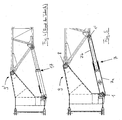
- FIGS. 4 and 5 show the expensive embodiment of a bending device with a hydraulic cylinder according to the prior art ( Figure 4) one Execution according to the invention compared.
- Figure 4 shows the Articulated area 9 'of the folding tip, with a pressure load on the lower side is present, a hydraulic cylinder 17 is arranged between two joints.
- Figure 5 instead of the hydraulic cylinder, a telescopic tube 7 is used.
- a telescopic tube 7 is used instead of the hydraulic cylinder.
- the Telescopic tube 7 has the base tube 7a and the extendable piston 7b the positions designated 1 and 1 'as shown in Figure 5 on the folding tip be articulated.
- the base tube 7a and the extendable piston 7b, the here is also designed as a tube, can be completely prefabricated and then simply pushed into each other. By inserting or The length of the bolt can be omitted, which will be discussed in more detail later Overall arrangement, that is, the total length of the telescopic tube 7 can be changed.
- the base tube 7a has a cross section the point with the bolt 2 in Figure 6 shows cross holes, one of which with the reference numeral 6 is indicated.
- Support bolts 2 are used, one of which is shown in Figure 6.
- This Support bolts support the lower part of the piston 7b (on different Set) in certain lengths for the entire telescopic tube 7.
- the base tube 7a does not have to be processed on the inside.
- the centering is over the Bolt 2 and the fillet or groove in the piston crown 3 in one axis and in the other axis by the piston 7b and those provided with the reference numeral 4 Welding hubs realized so that the guide is independent of the Manufacturing tolerances of the pipe is.
- the welding hubs 4 form how 7, reinforcements on the edges of the Through holes 6, the surface pressure due to larger sheet thicknesses can be reduced between bolt 2 and pipe wall.
- the welding hubs 4 thus have two functions, namely the centering of the piston 7b in the one hand Base tube 7a and on the other hand the reinforcement as support elements in the area of Through holes.
- the bolt in the bearing 1 ( Figures 5 and 6) in addition to its function as a hinge pin as a counter bearing (support) for the piston 7b can be used in the inserted state. This will make the dead length reduced and the overlap when extended extended. The bigger one Overlap has a positive effect on buckling safety.
- the spacer sleeve 5 is shown, which the Pulling apart of the telescopic tube prevented, so that the folding tip in can not "tip over" when it is not angled. Since the lower opening on the base tube 7a a simple pushing the parts 7a and 7b enables the piston crown 3 to be firmly connected to the piston tube. A simple assembly of the telescopic tube 7 is thus possible.
- the piston crown 3 can also be designed to be removable.
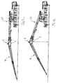
- FIGS. 9 and 10 show the erection of the jib of a mobile crane 20 the folding tip 10. Since the piston 7b, as shown in Figures 5 to 8, only on one side on one of the selected or inserted bolts (2 or 1) supports, the setting of the bolts can easily be done in a state at which the crane tip has no or only a very small angle, as in Figure 9 is shown. In the state shown in FIG. 9, the End angle position by inserting the bolt into the base tube 7a Telescopic tube 7 can be set at the desired location. If so, as in 10, the boom is raised, the telescopic tube 7 is shortened until the piston 7b hits the pin (2 or 1) and is supported on it. In FIG.
- the special construction according to the present invention makes it possible to the desired angle of the folding tip (length of the telescopic tube) with small Select the main boom angle. The tip then angles when lifting the Main boom until the telescopic tube has reached the preselected length. It is no further securing of the tip required, making all setup work in Near the ground are possible. So it becomes an inexpensive alternative to expensive ones Hydraulic cylinder devices provided by the invention that are convenient Set up on the ground without risk of accident.
Landscapes
- Engineering & Computer Science (AREA)
- Mechanical Engineering (AREA)
- Jib Cranes (AREA)
- Mutual Connection Of Rods And Tubes (AREA)
Applications Claiming Priority (2)
| Application Number | Priority Date | Filing Date | Title |
|---|---|---|---|
| DE10321493 | 2003-05-13 | ||
| DE10321493A DE10321493B4 (de) | 2003-05-13 | 2003-05-13 | Klappspitzen-Abwinklungsvorrichtung |
Publications (3)
| Publication Number | Publication Date |
|---|---|
| EP1477451A2 true EP1477451A2 (fr) | 2004-11-17 |
| EP1477451A3 EP1477451A3 (fr) | 2005-11-16 |
| EP1477451B1 EP1477451B1 (fr) | 2007-02-28 |
Family
ID=33016375
Family Applications (1)
| Application Number | Title | Priority Date | Filing Date |
|---|---|---|---|
| EP04006222A Expired - Lifetime EP1477451B1 (fr) | 2003-05-13 | 2004-03-16 | Dispositif de déroulement pour une flèchette de grue mobile |
Country Status (7)
| Country | Link |
|---|---|
| US (1) | US7131548B2 (fr) |
| EP (1) | EP1477451B1 (fr) |
| JP (1) | JP4727946B2 (fr) |
| CN (1) | CN100354195C (fr) |
| CA (1) | CA2465464C (fr) |
| DE (2) | DE10321493B4 (fr) |
| ES (1) | ES2279244T3 (fr) |
Cited By (4)
| Publication number | Priority date | Publication date | Assignee | Title |
|---|---|---|---|---|
| WO2009026870A1 (fr) * | 2007-08-29 | 2009-03-05 | Terex-Demag Gmbh | Élément de liaison pour un système à treillis |
| WO2009033198A1 (fr) * | 2007-09-11 | 2009-03-19 | Franz Ehrenleitner | Flèche repliable |
| DE202008015659U1 (de) | 2008-11-26 | 2009-03-19 | Palfinger Ag | Kranspitze für einen Ladekran |
| EP2253576A1 (fr) | 2009-05-22 | 2010-11-24 | Terex Demag GmbH | Ajustement d'angle d'un système de flèche |
Families Citing this family (22)
| Publication number | Priority date | Publication date | Assignee | Title |
|---|---|---|---|---|
| DE102005049606B4 (de) * | 2005-10-17 | 2016-03-31 | Liebherr-Werk Ehingen Gmbh | Fahrzeugkran mit Zusatzausleger und Verfahren zur Demontage des Hilfsauslegers |
| US7878346B1 (en) | 2008-08-25 | 2011-02-01 | Link-Belt Construction Equipment Co., L.P., Lllp | Adaptable boom extension for a mobile crane having a telescoping boom |
| DE102009010452A1 (de) * | 2009-02-26 | 2010-09-02 | Terex-Demag Gmbh | Verfahren und Einrichtung zum An-und Abbau einer Zusatzeinrichtung am Hauptausleger eines Mobilkrans |
| US8739988B2 (en) * | 2010-09-20 | 2014-06-03 | Manitowoc Crane Companies, Llc | Pinned connection system for crane column segments |
| DE202010014104U1 (de) * | 2010-10-08 | 2012-01-10 | Liebherr-Werk Ehingen Gmbh | Auslegerelement, Ausleger sowie Baufahrzeug |
| JP5609686B2 (ja) * | 2011-02-04 | 2014-10-22 | コベルコクレーン株式会社 | 移動式クレーン |
| CN102718156B (zh) * | 2012-06-29 | 2014-05-21 | 三一重工股份有限公司 | 起重机臂架系统及起重机 |
| CN102756978A (zh) * | 2012-07-20 | 2012-10-31 | 辽宁抚挖重工机械股份有限公司 | 一种履带起重机折叠臂 |
| DE102013006259B4 (de) * | 2013-04-11 | 2024-09-12 | Liebherr-Werk Ehingen Gmbh | Teleskopausleger und Kran |
| CN103449319B (zh) * | 2013-09-06 | 2015-12-02 | 中联重科股份有限公司 | 起重臂及起重机 |
| CN103601084B (zh) * | 2013-11-29 | 2015-08-12 | 三一汽车起重机械有限公司 | 臂尖滑轮机构、臂尖滑轮机构的自拆装方法及起重机 |
| CN104071710B (zh) * | 2014-07-01 | 2017-08-25 | 徐工集团工程机械股份有限公司 | 一种起重机及其无级变幅副臂装置 |
| DE102015002626A1 (de) * | 2015-03-03 | 2016-09-08 | Liebherr-Werk Ehingen Gmbh | Teleskopausleger eines Krans und Verfahren zu seiner Abspannung, sowie zum Aufrichten von Teleskopverlängerungen |
| CN105060140B (zh) * | 2015-08-19 | 2018-03-16 | 徐州重型机械有限公司 | 起重机的副臂、起重臂和起重机 |
| DE102015119379B3 (de) | 2015-11-10 | 2017-03-30 | Terex Global Gmbh | Mobilkran und Verfahren zum Abwinkeln einer Hauptauslegerverlängerung relativ zu einem Hauptausleger eines Mobilkrans |
| DE102015119381B3 (de) * | 2015-11-10 | 2017-04-27 | Terex Global Gmbh | Mobilkran und Verfahren zum Abwinkeln einer Hauptauslegerverlängerung relativ zu einem Hauptausleger eines Mobilkrans |
| DE102015120350B3 (de) | 2015-11-24 | 2017-05-24 | Terex Global Gmbh | Mobilkran zum Abwinkeln einer Hauptauslegerverlängerung relativ zu einem Hauptausleger eines Mobilkrans |
| CN106241628A (zh) * | 2016-08-25 | 2016-12-21 | 徐州重型机械有限公司 | 桁架臂结构及起重机 |
| DE102018115519B3 (de) | 2018-06-27 | 2019-09-12 | Terex Global Gmbh | Fahrzeugkran mit einem beweglichen Adapter zwischen Hauptausleger und Hauptauslegerverlängerung |
| CN110193869A (zh) * | 2019-07-09 | 2019-09-03 | 邢珊珊 | 一种含折叠挤压机构的木材加工机 |
| CN111943063B (zh) * | 2020-08-19 | 2022-08-12 | 东台市杰顺机械制造有限公司 | 一种用于飞轮壳加工生产的柔性紧固提拉装置 |
| DE102020134714B4 (de) * | 2020-12-22 | 2023-09-28 | Tadano Demag Gmbh | Fahrzeugkran mit einem wippbaren Hauptausleger und mit einem Zusatzauslegersystem |
Family Cites Families (34)
| Publication number | Priority date | Publication date | Assignee | Title |
|---|---|---|---|---|
| DE291531C (fr) | ||||
| US2147313A (en) * | 1936-06-23 | 1939-02-14 | Payson Rudolph | Telescopic hoisting apparatus |
| US2198793A (en) * | 1937-09-02 | 1940-04-30 | Yale & Towne Mfg Co | Tilting boom |
| US2512150A (en) * | 1947-01-08 | 1950-06-20 | Airquipment Company | Hydraulic ram mechanism having shielding and stop means |
| US3092261A (en) * | 1960-03-23 | 1963-06-04 | Patent Resources Inc | Crane boom safety apparatus |
| US3085695A (en) * | 1961-03-23 | 1963-04-16 | Carl A Miller | Hinge for crane boom |
| US3638804A (en) * | 1969-09-17 | 1972-02-01 | Pacific Gas Equipment Co | Hoisting apparatus |
| US3754666A (en) * | 1970-03-09 | 1973-08-28 | Hopper Inc | Folding crane |
| US3899089A (en) * | 1974-02-05 | 1975-08-12 | N J Wardlaw | Removable mounted hoist for pick-up truck |
| US3944082A (en) | 1974-12-20 | 1976-03-16 | Harnischfeger Corporation | Locking means for relatively movable boom sections of boom of mobile crane |
| SU619588A1 (ru) * | 1976-10-20 | 1978-08-15 | Строительно-Монтажное Управление N1 Треста "Востокпроводмеханизация" | Рабочее оборудование гидравлического экскаватора |
| FR2444639A1 (fr) * | 1978-12-20 | 1980-07-18 | Potain Sa | Equipement de manutention, notamment pour un engin automoteur |
| DD139830B1 (de) * | 1978-12-21 | 1982-10-27 | Horst Bendix | Zusatzausleger fuer eisenbahn-spezialkrane oder dergleichen |
| US4484686A (en) * | 1982-04-23 | 1984-11-27 | Kidde, Inc. | Multiple offset boom extension |
| JPS59173689A (ja) * | 1983-03-23 | 1984-10-01 | Hitachi Ltd | 熱伝達装置 |
| JPS6043690A (ja) * | 1983-08-19 | 1985-03-08 | 三洋電機株式会社 | Crt端末装置 |
| GB2160170A (en) * | 1984-06-15 | 1985-12-18 | Didsbury Eng | Davit (especially for vehicles) |
| US4621742A (en) * | 1985-01-25 | 1986-11-11 | Harnischfeger Corporation | Boom extension storage means and mechanisms |
| JPH07115831B2 (ja) * | 1988-05-06 | 1995-12-13 | 株式会社神戸製鋼所 | クレーンのジブ張出し、格納装置 |
| US4953724A (en) * | 1989-06-29 | 1990-09-04 | Kabushiki Kaisha Kobe Seiko Sho | Jib stretching and folding device |
| CA2015519C (fr) * | 1989-08-10 | 1994-09-27 | Yukio Koizumi | Dispositif de deploiement et de repliement de la fleche d'une grue |
| DD291531A5 (de) * | 1990-01-08 | 1991-07-04 | Maschinenbau "Karl Marx",De | Ausleger mit einer vorrichtung fuer ein- oder mehrteilige abwippbare auslegerverlaengerungen fuer krane, insbesondere mobile krane |
| JP2781637B2 (ja) * | 1990-03-16 | 1998-07-30 | 株式会社神戸製鋼所 | クレーンにおけるジブ支持ロッドの取付装置 |
| CA2036895A1 (fr) * | 1991-02-22 | 1992-08-23 | James Vandervalk | Grue mobile |
| US5725112A (en) * | 1991-12-17 | 1998-03-10 | Thorby; Donald Frederick | Crane |
| DE9318480U1 (de) * | 1993-12-02 | 1994-03-10 | Buck, Erwin, 88267 Vogt | Gabelhubwagen zum Heben und Senken sowie Transportieren von Lasten |
| FR2719574B1 (fr) * | 1994-05-06 | 1996-07-26 | Ppm | Ensemble de prolongation pour flèche télescopique de grue mobile et grue mobile en faisant application. |
| US5758785A (en) * | 1995-06-22 | 1998-06-02 | Spinosa; Dominic | Lifting system |
| US5704498A (en) * | 1996-09-25 | 1998-01-06 | Kidde Industries, Inc. | Transportable crane |
| DE19731587A1 (de) * | 1997-07-17 | 1999-01-28 | Mannesmann Ag | Teleskopkran mit wippbarem Hilfsausleger |
| CN1242337A (zh) * | 1998-07-01 | 2000-01-26 | 美国格若沃责任有限公司 | 移动式吊车 |
| DE19932009A1 (de) * | 1998-07-07 | 2000-01-27 | Mannesmann Ag | Fahrbarer Kran mit einem Teleskopausleger |
| FR2794734B1 (fr) * | 1999-06-10 | 2001-07-13 | Potain Sa | Chariot automoteur a bras telescopique et rehausse |
| ITMI20010116A1 (it) * | 2001-01-23 | 2002-07-23 | San Marco Internat S R L | Gru a torre a struttura composita automontante con torre ripiegabile e sfilabile e braccio a piu' porzioni |
-
2003
- 2003-05-13 DE DE10321493A patent/DE10321493B4/de not_active Expired - Fee Related
-
2004
- 2004-03-16 DE DE502004003002T patent/DE502004003002D1/de not_active Expired - Lifetime
- 2004-03-16 ES ES04006222T patent/ES2279244T3/es not_active Expired - Lifetime
- 2004-03-16 EP EP04006222A patent/EP1477451B1/fr not_active Expired - Lifetime
- 2004-04-20 US US10/827,242 patent/US7131548B2/en not_active Expired - Lifetime
- 2004-04-27 CA CA002465464A patent/CA2465464C/fr not_active Expired - Fee Related
- 2004-05-11 JP JP2004141181A patent/JP4727946B2/ja not_active Expired - Lifetime
- 2004-05-13 CN CNB200410043130XA patent/CN100354195C/zh not_active Expired - Fee Related
Cited By (6)
| Publication number | Priority date | Publication date | Assignee | Title |
|---|---|---|---|---|
| WO2009026870A1 (fr) * | 2007-08-29 | 2009-03-05 | Terex-Demag Gmbh | Élément de liaison pour un système à treillis |
| US8414214B2 (en) | 2007-08-29 | 2013-04-09 | Terex Cranes Germany Gmbh | Element for connecting a lattice system |
| WO2009033198A1 (fr) * | 2007-09-11 | 2009-03-19 | Franz Ehrenleitner | Flèche repliable |
| DE202008015659U1 (de) | 2008-11-26 | 2009-03-19 | Palfinger Ag | Kranspitze für einen Ladekran |
| EP2253576A1 (fr) | 2009-05-22 | 2010-11-24 | Terex Demag GmbH | Ajustement d'angle d'un système de flèche |
| DE102009022262A1 (de) | 2009-05-22 | 2010-11-25 | Terex Demag Gmbh | Winkelverstellung eines Auslegersystems |
Also Published As
| Publication number | Publication date |
|---|---|
| DE10321493B4 (de) | 2006-07-20 |
| US7131548B2 (en) | 2006-11-07 |
| US20050011850A1 (en) | 2005-01-20 |
| JP2004338953A (ja) | 2004-12-02 |
| JP4727946B2 (ja) | 2011-07-20 |
| ES2279244T3 (es) | 2007-08-16 |
| CN100354195C (zh) | 2007-12-12 |
| DE10321493A1 (de) | 2004-12-23 |
| EP1477451B1 (fr) | 2007-02-28 |
| CA2465464A1 (fr) | 2004-11-13 |
| EP1477451A3 (fr) | 2005-11-16 |
| CN1621334A (zh) | 2005-06-01 |
| CA2465464C (fr) | 2010-01-19 |
| DE502004003002D1 (de) | 2007-04-12 |
Similar Documents
| Publication | Publication Date | Title |
|---|---|---|
| DE10321493B4 (de) | Klappspitzen-Abwinklungsvorrichtung | |
| EP2465809B1 (fr) | Système de télescopage pour flèche et flèche auxiliaire | |
| EP3337752B1 (fr) | Grue mobile et procédé pour permettre un déplacement angulaire d'une rallonge de flèche principale par rapport à une flèche principale d'une grue mobile | |
| WO2017081021A1 (fr) | Grue mobile et procédé pour permettre un déplacement angulaire d'une rallonge de flèche principale par rapport à une flèche principale d'une grue mobile | |
| EP2067737B1 (fr) | Haubanage latéral pour un bras à grille d'une grue | |
| DE102017117958B4 (de) | Kran und Gegengewicht für einen Kran | |
| DE102011115355B4 (de) | Auslegerelement, Teleskopausleger sowie Baufahrzeug | |
| EP3564182B1 (fr) | Pompe à béton automatique | |
| DE102019104142B9 (de) | Klappbare Schwebeballastführung für einen Kran | |
| DE102011115357B4 (de) | Auslegerelement, Teleskopausleger, Verbolzsystem sowie Baufahrzeug | |
| DE202007012764U1 (de) | Auslegerkran, Hilfsausleger und Zwischenstück | |
| DE102013011173B4 (de) | Verfahren zur Montage eines Krans sowie Anlenkschuss, Teleskopausleger und Kran | |
| DE10028997A1 (de) | Anbaurahmen für Vorsatzgeräte einer Arbeitsmaschine und zugehöriger Aufnahmebolzen | |
| EP3556718B1 (fr) | Vehicule de pompe à béton | |
| EP3656947B1 (fr) | Pompe à béton automatique | |
| EP0893392A2 (fr) | Grue télescopique avec flechette relevable | |
| EP3477018B1 (fr) | Levier creux à deux points | |
| WO2018115271A1 (fr) | Grue pourvue d'un bras rabattable | |
| DE202008015659U1 (de) | Kranspitze für einen Ladekran | |
| DE102022128653B4 (de) | Fahrbarer Kran mit Gittermastausleger, Gittermastausleger sowie Verfahren zur Montage eines solchen | |
| DE202016100483U1 (de) | Fahrzeug-Leichtkran mit teleskopierbarer Klappspitze | |
| EP1373120A1 (fr) | Fleche telescopique pour une grue automotrice | |
| DE102020112526B4 (de) | Vorrichtung und Verfahren zur Abspannung, Fliegendmontage und Rückrüstung eines Gitterauslegers | |
| EP0685422B1 (fr) | Dispositif pour l'érection et l'alignement d'une grue à montage automatisé | |
| DE202009013085U1 (de) | Fahrzeugkran |
Legal Events
| Date | Code | Title | Description |
|---|---|---|---|
| PUAI | Public reference made under article 153(3) epc to a published international application that has entered the european phase |
Free format text: ORIGINAL CODE: 0009012 |
|
| AK | Designated contracting states |
Kind code of ref document: A2 Designated state(s): AT BE BG CH CY CZ DE DK EE ES FI FR GB GR HU IE IT LI LU MC NL PL PT RO SE SI SK TR |
|
| AX | Request for extension of the european patent |
Extension state: AL LT LV MK |
|
| PUAL | Search report despatched |
Free format text: ORIGINAL CODE: 0009013 |
|
| AK | Designated contracting states |
Kind code of ref document: A3 Designated state(s): AT BE BG CH CY CZ DE DK EE ES FI FR GB GR HU IE IT LI LU MC NL PL PT RO SE SI SK TR |
|
| AX | Request for extension of the european patent |
Extension state: AL LT LV MK |
|
| 17P | Request for examination filed |
Effective date: 20060118 |
|
| AKX | Designation fees paid |
Designated state(s): DE ES FR GB IT |
|
| GRAP | Despatch of communication of intention to grant a patent |
Free format text: ORIGINAL CODE: EPIDOSNIGR1 |
|
| GRAS | Grant fee paid |
Free format text: ORIGINAL CODE: EPIDOSNIGR3 |
|
| GRAA | (expected) grant |
Free format text: ORIGINAL CODE: 0009210 |
|
| AK | Designated contracting states |
Kind code of ref document: B1 Designated state(s): DE ES FR GB IT |
|
| REG | Reference to a national code |
Ref country code: GB Ref legal event code: FG4D Free format text: NOT ENGLISH |
|
| GBT | Gb: translation of ep patent filed (gb section 77(6)(a)/1977) |
Effective date: 20070228 |
|
| REF | Corresponds to: |
Ref document number: 502004003002 Country of ref document: DE Date of ref document: 20070412 Kind code of ref document: P |
|
| REG | Reference to a national code |
Ref country code: DE Ref legal event code: R096 Ref document number: 502004003002 Country of ref document: DE Effective date: 20070412 |
|
| REG | Reference to a national code |
Ref country code: ES Ref legal event code: FG2A Ref document number: 2279244 Country of ref document: ES Kind code of ref document: T3 |
|
| ET | Fr: translation filed | ||
| PLBE | No opposition filed within time limit |
Free format text: ORIGINAL CODE: 0009261 |
|
| STAA | Information on the status of an ep patent application or granted ep patent |
Free format text: STATUS: NO OPPOSITION FILED WITHIN TIME LIMIT |
|
| 26N | No opposition filed |
Effective date: 20071129 |
|
| REG | Reference to a national code |
Ref country code: DE Ref legal event code: R097 Ref document number: 502004003002 Country of ref document: DE Effective date: 20071129 |
|
| REG | Reference to a national code |
Ref country code: GB Ref legal event code: 732E Free format text: REGISTERED BETWEEN 20110915 AND 20110921 |
|
| REG | Reference to a national code |
Ref country code: FR Ref legal event code: TP Owner name: MANITOWOC CRANE GROUP FRANCE, FR Effective date: 20110920 |
|
| REG | Reference to a national code |
Ref country code: ES Ref legal event code: PC2A Owner name: MANITOWOC CRANE GROUP FRANCE SAS Effective date: 20111027 |
|
| REG | Reference to a national code |
Ref country code: DE Ref legal event code: R082 Ref document number: 502004003002 Country of ref document: DE Representative=s name: SCHWABE SANDMAIR MARX, DE |
|
| REG | Reference to a national code |
Ref country code: DE Ref legal event code: R081 Ref document number: 502004003002 Country of ref document: DE Owner name: MANITOWOC CRANE GROUP FRANCE SAS, FR Free format text: FORMER OWNER: GROVE U.S. LLC, SHADY GROVE, PA., US Effective date: 20120330 Ref country code: DE Ref legal event code: R082 Ref document number: 502004003002 Country of ref document: DE Representative=s name: SCHWABE SANDMAIR MARX, DE Effective date: 20120330 Ref country code: DE Ref legal event code: R081 Ref document number: 502004003002 Country of ref document: DE Owner name: MANITOWOC CRANE GROUP FRANCE SAS, FR Free format text: FORMER OWNER: GROVE U.S. LLC, SHADY GROVE, US Effective date: 20120330 Ref country code: DE Ref legal event code: R082 Ref document number: 502004003002 Country of ref document: DE Representative=s name: SCHWABE SANDMAIR MARX PATENTANWAELTE RECHTSANW, DE Effective date: 20120330 |
|
| PGFP | Annual fee paid to national office [announced via postgrant information from national office to epo] |
Ref country code: GB Payment date: 20130321 Year of fee payment: 10 |
|
| GBPC | Gb: european patent ceased through non-payment of renewal fee |
Effective date: 20140316 |
|
| PG25 | Lapsed in a contracting state [announced via postgrant information from national office to epo] |
Ref country code: GB Free format text: LAPSE BECAUSE OF NON-PAYMENT OF DUE FEES Effective date: 20140316 |
|
| REG | Reference to a national code |
Ref country code: DE Ref legal event code: R082 Ref document number: 502004003002 Country of ref document: DE Representative=s name: SCHWABE SANDMAIR MARX, DE |
|
| REG | Reference to a national code |
Ref country code: DE Ref legal event code: R081 Ref document number: 502004003002 Country of ref document: DE Owner name: MANITOWOC CRANE GROUP FRANCE SAS, FR Free format text: FORMER OWNER: MANITOWOC CRANE GROUP FRANCE SAS, ECULLY, FR Effective date: 20150317 Ref country code: DE Ref legal event code: R082 Ref document number: 502004003002 Country of ref document: DE Representative=s name: SCHWABE SANDMAIR MARX, DE Effective date: 20150317 Ref country code: DE Ref legal event code: R082 Ref document number: 502004003002 Country of ref document: DE Representative=s name: SCHWABE SANDMAIR MARX PATENTANWAELTE RECHTSANW, DE Effective date: 20150317 |
|
| REG | Reference to a national code |
Ref country code: FR Ref legal event code: PLFP Year of fee payment: 13 |
|
| REG | Reference to a national code |
Ref country code: FR Ref legal event code: PLFP Year of fee payment: 14 |
|
| REG | Reference to a national code |
Ref country code: FR Ref legal event code: PLFP Year of fee payment: 15 |
|
| PGFP | Annual fee paid to national office [announced via postgrant information from national office to epo] |
Ref country code: ES Payment date: 20200522 Year of fee payment: 17 |
|
| REG | Reference to a national code |
Ref country code: ES Ref legal event code: FD2A Effective date: 20220523 |
|
| PG25 | Lapsed in a contracting state [announced via postgrant information from national office to epo] |
Ref country code: ES Free format text: LAPSE BECAUSE OF NON-PAYMENT OF DUE FEES Effective date: 20210317 |
|
| PGFP | Annual fee paid to national office [announced via postgrant information from national office to epo] |
Ref country code: FR Payment date: 20230321 Year of fee payment: 20 |
|
| PGFP | Annual fee paid to national office [announced via postgrant information from national office to epo] |
Ref country code: DE Payment date: 20230321 Year of fee payment: 20 |
|
| P01 | Opt-out of the competence of the unified patent court (upc) registered |
Effective date: 20230515 |
|
| PGFP | Annual fee paid to national office [announced via postgrant information from national office to epo] |
Ref country code: IT Payment date: 20230328 Year of fee payment: 20 |
|
| REG | Reference to a national code |
Ref country code: DE Ref legal event code: R071 Ref document number: 502004003002 Country of ref document: DE |