EP1477620A1 - Befestigungselement für Betonbauteile und Verwendungen desselben - Google Patents
Befestigungselement für Betonbauteile und Verwendungen desselben Download PDFInfo
- Publication number
- EP1477620A1 EP1477620A1 EP04011081A EP04011081A EP1477620A1 EP 1477620 A1 EP1477620 A1 EP 1477620A1 EP 04011081 A EP04011081 A EP 04011081A EP 04011081 A EP04011081 A EP 04011081A EP 1477620 A1 EP1477620 A1 EP 1477620A1
- Authority
- EP
- European Patent Office
- Prior art keywords
- concrete
- fastening element
- padding
- fastener
- profile
- Prior art date
- Legal status (The legal status is an assumption and is not a legal conclusion. Google has not performed a legal analysis and makes no representation as to the accuracy of the status listed.)
- Granted
Links
- 239000004567 concrete Substances 0.000 title claims description 82
- 238000010276 construction Methods 0.000 title 1
- 229910000831 Steel Inorganic materials 0.000 claims abstract 2
- 239000010959 steel Substances 0.000 claims abstract 2
- 239000000463 material Substances 0.000 claims description 7
- 229910001220 stainless steel Inorganic materials 0.000 claims description 3
- 239000010935 stainless steel Substances 0.000 claims description 3
- 239000012858 resilient material Substances 0.000 abstract 2
- 238000004080 punching Methods 0.000 description 15
- 230000002787 reinforcement Effects 0.000 description 8
- 238000009434 installation Methods 0.000 description 7
- XEEYBQQBJWHFJM-UHFFFAOYSA-N Iron Chemical compound [Fe] XEEYBQQBJWHFJM-UHFFFAOYSA-N 0.000 description 4
- 238000009413 insulation Methods 0.000 description 3
- 238000012546 transfer Methods 0.000 description 3
- 229910052742 iron Inorganic materials 0.000 description 2
- 238000012549 training Methods 0.000 description 2
- QCDFBFJGMNKBDO-UHFFFAOYSA-N Clioquinol Chemical compound C1=CN=C2C(O)=C(I)C=C(Cl)C2=C1 QCDFBFJGMNKBDO-UHFFFAOYSA-N 0.000 description 1
- 238000004026 adhesive bonding Methods 0.000 description 1
- 230000005540 biological transmission Effects 0.000 description 1
- 239000011248 coating agent Substances 0.000 description 1
- 238000000576 coating method Methods 0.000 description 1
- 230000006835 compression Effects 0.000 description 1
- 238000007906 compression Methods 0.000 description 1
- 238000013461 design Methods 0.000 description 1
- 230000000694 effects Effects 0.000 description 1
- 238000001125 extrusion Methods 0.000 description 1
- 230000002349 favourable effect Effects 0.000 description 1
- 239000006261 foam material Substances 0.000 description 1
- 238000002347 injection Methods 0.000 description 1
- 239000007924 injection Substances 0.000 description 1
- 238000003780 insertion Methods 0.000 description 1
- 230000037431 insertion Effects 0.000 description 1
- 238000010409 ironing Methods 0.000 description 1
- 238000000034 method Methods 0.000 description 1
- 239000011150 reinforced concrete Substances 0.000 description 1
- 239000000725 suspension Substances 0.000 description 1
Images

Classifications
-
- E—FIXED CONSTRUCTIONS
- E04—BUILDING
- E04B—GENERAL BUILDING CONSTRUCTIONS; WALLS, e.g. PARTITIONS; ROOFS; FLOORS; CEILINGS; INSULATION OR OTHER PROTECTION OF BUILDINGS
- E04B1/00—Constructions in general; Structures which are not restricted either to walls, e.g. partitions, or floors or ceilings or roofs
- E04B1/38—Connections for building structures in general
- E04B1/48—Dowels, i.e. members adapted to penetrate the surfaces of two parts and to take the shear stresses
- E04B1/483—Shear dowels to be embedded in concrete
-
- E—FIXED CONSTRUCTIONS
- E01—CONSTRUCTION OF ROADS, RAILWAYS, OR BRIDGES
- E01C—CONSTRUCTION OF, OR SURFACES FOR, ROADS, SPORTS GROUNDS, OR THE LIKE; MACHINES OR AUXILIARY TOOLS FOR CONSTRUCTION OR REPAIR
- E01C11/00—Details of pavings
- E01C11/02—Arrangement or construction of joints; Methods of making joints; Packing for joints
- E01C11/04—Arrangement or construction of joints; Methods of making joints; Packing for joints for cement concrete paving
- E01C11/14—Dowel assembly ; Design or construction of reinforcements in the area of joints
Definitions
- the present invention relates to a fastener for embedding with a End portion in a concrete component and for absorbing transverse forces, wherein on the End portion in the direction of the male transverse forces alignable faces are present, which with respect to this direction a front and a opposite this staggered arranged rear surface part.
- the invention further relates to uses of such a fastener.
- Double thrust dome known which as connecting elements between two components made of reinforced concrete, between which a certain relative movement must be possible.
- the Doppelschubdome serve here for recording and Transmission of shear forces.
- the known double-thrust domes each consist of two spaced circular domes passing through a power plate and a rigid connecting web are connected together. While only one End portion of the double thrust dome is embedded in one of the two components, the opposite end portion is inserted in sliding sleeves, in the other Concrete component are cast in concrete.
- the double-thrust domes are aligned so that the two domes offset in the direction of the lateral force come to rest one behind the other. at vertical shear force direction simply means "upright".
- Cantilever connections For thermally insulated connection of cantilevers as e.g. from outside balcony slabs on in-building floors, so-called Cantilever connections used. Also these cantilever connections must Transverse forces transmitted and are about with s-shaped running concrete iron Mistake.
- the present invention has as its object the loading capacity of Fasteners of the type mentioned, including in particular the mentioned double thrusts, to increase substantially with simple means.
- the invention proposes the rear part surface with a To provide upholstery, as characterized in claim 1.
- the rear part surface prevents this part of the surface Concreting immediately comes in contact with the concrete and rigid in the concrete is embedded. About this part of a load can thus practically not in the Concrete can be initiated. Under stress it comes at best to a certain Compression of the padding, which the applied pressure, if any, only soft passes to the concrete. In the inventive fastener Therefore, the load is almost exclusively on the aligned in Beiastungsraum and transferred with respect to this direction front surface of the concrete. This one Half kaue a greater distance from the lying in the loading direction Concrete surface, results in respect of this part of a larger area potential puncture wedge and thus a higher security against punching.
- the padding provided according to the invention can be of virtually any kind, as long as they are essentially just the pressure of fresh concrete while concreting withstands a load of the fastener but sufficiently yielding reacts to prevent a load transfer into the concrete or at least sufficiently reduce.
- the inventive Fastener i. if the concrete surrounding the element has set, it did not need any padding at all.
- a certain cavity at the place of Upholstery would be enough. Therefore, the upholstery can also be understood are used as a kind of placeholder to create a cavity-like structure Concrete.
- upholstery in particular, e.g. can be applied by gluing Layers of a dimensionally stable foam material.
- the fastener according to the invention can advantageously be used e.g. when Double thrust dome for connecting two concrete components in the area of an expansion joint be formed and used together with a corresponding sliding sleeve be as described at the beginning of the prior art, wherein the Of course, padding according to the invention must additionally be provided.
- the upholstery could only on one side, i. only in relation to one of the two concrete components as well as possibly only partially used.
- it is preferred in the area attached to both end portions of the fastener so both in the area the firmly concreted end portion as well as guided in the sliding sleeve End portion.
- a particularly advantageous embodiment results from the choice of a T-shaped or double T-shaped cross-section for the fastener.
- Fasteners according to the invention can also be fixed with both end portions be embedded in a concrete component, if a relative movement of both concrete components at least away from each other or towards each other not too get or allowed and possibly only a small parallel shift between the two concrete components must be possible, as e.g. both initially also already mentioned cantilever connections is the case.
- the Padding according to the invention could in this case again on both sides, in particular Cases but only one-sided and possibly only part of the area provided.
- the fastening element according to the invention can with further advantage also as a kind of universal anchor in particular for suspension heavy components are used.
- the Doppelschubdom 10 has a double-T-shaped Profile, which is composed of two C-shaped profiles. Both Outer surfaces 11 and 12 of the profile are each full surface with a padding thirteenth or 14 provided.
- the two C-profiles consist e.g. made of stainless steel.
- the sliding sleeve 20 is made e.g. made of a plastic material and is in particular produced as an injection molded part. Their shape is chosen so that the Double thrust mandrel 10 with one of its end portions in its opening 21 can be inserted.
- Fig. 2 shows a Fig. 1 substantially corresponding embodiment in which However, the here as 20'belei sliding sleeve is widened to the double thrust dome 10 'in addition to allow some latitude in the transverse direction.
- the padding 13 and 14 of Fig. 1 are in this embodiment only outside the sliding sleeve 20 'applied to the double thrust dome.
- the double thrust mandrel 10 ' In the area of the sliding sleeve is the double thrust mandrel 10 ', however, ungepostert, whereas upholstery 23 and 24th and 24 are applied to the outside of the sliding sleeve.
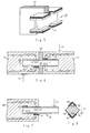
- Fig. 3 shows a typical installation situation of the double thrust dome 10 and the Sliding sleeve 20 in two adjacent to each other along an expansion joint 30 plate-shaped concrete components 40 and 50.
- the Doppelschubdom 10 is with his left end portion poured into the concrete of the concrete component 40 and with his right end portion 16 inserted into the sliding sleeve 20, which in turn in the Concrete of the right concrete component 50 is poured.
- the length of the sliding sleeve 20 is so measured that the right end portion of the Doppelschubdorens 10 in her with regard to on the expected strains or narrowing of the joint 30 at all times sufficient insertion depth is longitudinally displaceable.
- the conditions are accurate under the conditions of FIG vice versa.
- the external lateral force F1 to the lower inner surfaces 16 of the double-T-shaped profile directed upward Surface pressures F1 ', so that the padding 13 is effective, which the training corresponding surface pressures on the upper outer surface 11 prevents which here forms the "back" partial surface.
- the padding 14 only in the concrete component 40 and the padding 13th to provide only in the concrete component 50.
- the full-surface coating of both However, outer surfaces 11 and 12 of the double-T-shaped profile has the advantage that thereby any installation errors due to incorrect orientation of the element safely be avoided and also the so-formed Doppelschubdom also in Cases can be used in which with a change in direction of the shear forces may even be rectified, as may be e.g. at two may be the case to be joined together floor panels.
- Fig. 5 shows a further embodiment of an inventive Fastener in a training as a cantilever plate connection with Insulating element for thermal insulation.
- the insulating element 68 is only partially shown to the view of the mittweekichen middle section 61 release. In fact, it should completely surround this middle section 67 and extend beyond the profile 60 on both sides. It can be at a height between 12 and 30 cm have a total length of up to 200 cm.
- the insulating element 68 except with the illustrated profile 60 with be further provided to parallel profiles 60 of the same kind.
- Fig. 6 shows a typical installation situation of a Kragplattenan gleiches approximately corresponding to that of Fig. 5, here the plate-shaped concrete member 44, e.g. a Floor ceiling of a building and the concrete component 55 on the building Externally attached projecting balcony plate is.
- the profile 60 is with his left End portion in the concrete of the concrete component 44 and with its right end portion poured into the concrete of the concrete component 55.
- the insulating element 68 forms a Thermal insulation between the lying inside the building ceiling 44 and the weather-exposed outer balcony slab 55.
- a kind of anchor 70 of again double T-shaped profile which with its left end portion in one any concrete component 80 (which could also be a wall) is poured and is at its protruding free right end portion any part e.g. could be hung up.
- any concrete component 80 which could also be a wall
- any part e.g. could be hung up is poured and is at its protruding free right end portion any part e.g. could be hung up.
- the Padding 74 corresponds in effect to the padding 64 of FIG. 6 and by the padding 73 of reversing the direction of load registration (surface pressure F3 ") to the left profile end towards account is taken.
- the padding 73 corresponding Upholsterings could also be useful added in the example of Fig. 6.
- a per se in the example of Fig. 7 also again preferred full-surface Padding of both profile outer surfaces 71 and 72 in the embedded end portion would be in any case, padding is present at all critical points, taking them where they are not needed, do not disturb.
- the embodiment of Fig. 7 is suitable especially as a heavy duty anchor.
- the double-T or double C-shaped used in the above examples Profile is preferred because it is in the various possible stress situations the Optionally absorb, transmit and initiate occurring transverse forces. Further preferred, as already mentioned, a full-surface padding his External surfaces, because then upholstery in any case at all critical points available which, on the other hand, do not disturb where they are not needed.
- the profile is e.g. in comparison with the double-thrust domes mentioned at the beginning
- the prior art also simple and inexpensive to produce, for. endless in an extrusion process.
- a non-ideally extrudable material e.g. Stainless steel proves the double C shape to be advantageous because the individual C profiles bent from a flat material in the C-shape and then only back need to be welded together.
- the double T-shaped profiles could have a length between 20 and 80 cm, a height between 6 and 50 cm and a width between 6 and 20 cm have a thickness of Range of T-flanges between 4 and 30 mm.
- a C-profile can be specified or even a single-T-profile.
- Fig.8 shows ledilgich to clarify the possible variety of geometry still a rather extreme and less favorable example in which one on one of his Rectangular profile 90 edges each partial surfaces 91 on both sides of the upper edge with a padding 93 and Operaf kauen 92 on both sides of the lower edge with a Padding 94 is provided.
Landscapes
- Engineering & Computer Science (AREA)
- Architecture (AREA)
- Civil Engineering (AREA)
- Structural Engineering (AREA)
- Physics & Mathematics (AREA)
- Electromagnetism (AREA)
- Joining Of Building Structures In Genera (AREA)
- Dowels (AREA)
Abstract
Description
- Fig. 1
- eine erste Ausführungsform eines erfindungsgemässen Befestigungselements in einer Ausbildung als Doppelschubdom mit zugehöriger Gleithülse;
- Fig. 2
- eine Variante der Ausführungsform von Fig. 1, bei welcher der Doppelschubdom in einer speziellen Gleithüsle auch querverschieblich ist;
- Fig. 3
- in einem Längsschnitt eine Einbausituation des Doppelschubdoms und der Gleithülse von Fig. 1 im Bereich einer Dehnfuge zwischen zwei Betonbauteilen;
- Fig. 4
- einen Querschnitt (A-A) durch das linke Bauteil von Fig. 3;
- Fig. 5
- eine weitere Ausführungsform eines erfindungsgemässen Befestigungselements in einer Ausbildung als Kragplattenanschluss mit Dämmstoffelement;
- Fig. 6
- in einem Längsschnitt eine Einbausituation des Kragplattenanschlusses von Fig. 4 im Bereich zwischen einer Geschossdecke und einer Balkonplatte, wobei die Polsterung gegenüber Fig. 5 jedoch nur selektiv und teilflächig ausgeführt ist;
- Fig. 7
- in einem Längsschnitt eine dritte Ausführungsform eines erfindungsgemässen Befestigungselements in einer Ausbildung als Schwerlastanker, einseitig eingebettet in ein Betonbauteil; und
- Fig. 8
- in einem Querschnitt eine noch weitere Ausführungsform eines erfindungsgemässen Befestigungselements in einer Ausbildung als Vierkantstab, welcher mit oberen und unteren Polsterungen versehen ist.
- 10, 10'
- Doppelschubdom mit Doppel-T-förmigem Profil
- 11
- obere Profil-Aussenfläche
- 12
- untere Profil-Aussenfläche
- 13
- Polsterung auf der Profilfläche 11
- 14
- Polsterung auf der Profilfläche 12
- 15
- nach unten ausgerichtete Profil-Innenflächen
- 16
- nach oben ausgerichtete Profil-Aussenflächen
- 20, 20'
- Gleithülse
- 21
- Öffnung der Gleithülse
- 23
- Polsterung
- 24
- Poslterung
- 30
- Dehnfuge
- 40
- plattenförmiges Betonbauteil
- 41
- untere Betonoberfläche des Betonbauteils 40
- 44
- Geschossdecke
- 50
- plattenförmiges Betonbauteil
- 55
- Balkonplatte
- 60
- Profil eines Kragplattenanschlusses
- 61
- obere Profil-Aussenfläche des Profils 60
- 62
- untere Profil-Aussenfläche des Profils 60
- 63
- Polsterung
- 64
- Polsterung
- 67
- Mittelteil des Kragplattenanschlusses
- 68
- Dämmstoffelement
- 70
- Anker
- 71
- Profil-Aussenfläche
- 72
- Profil-Aussenfläche
- 73
- Polsterung
- 74
- Polsterung
- 80
- Betonbauteil
- 90
- Rechteckprofil
- 91
- Teilflächen von 90
- 92
- Teilflächen von 90
- 93
- Polsterung
- 94
- Polsterung
- 95
- lastübertragende Teilflächen
- F1 - F4
- Querkräfte
- F1'- F3"
- Flächenpressungen
- D1-D3
- Durchstanzkeile
- Z1, Z2
- Zulagebewehrung
Claims (12)
- Befestigungselement (10; 10'; 60; 70; 90) zur Einbettung mit einem Endabschnitt in ein Betonbauteil (40, 50; 44, 55; 80) und zur Aufnahme von Querkräften (F1, F2; F3; F4), wobei an dem Endabschnitt in Richtung der aufzunehmenden Querkräfte ausrichtbare Teilflächen (11, 16, 12, 15; 61, 62; 91, 92, 95) vorhanden sind, welche bezüglich dieser Richtung eine vordere (15; 16; 95) und eine gegenüber dieser versetzt angeordnete hintere Teilläche (11, 12; 61, 62; 91, 92) umfassen, dadurch gekennzeichnet, dass die hintere Teilfläche mit einer Polsterung (13, 14; 63, 64; 73, 74; 93, 94) versehen ist.
- Befestigungselement nach Anspruch 1, dadurch gekennzeichnet, dass es aus Stahl, inbesondere aus einem nichtrostenden Stahl besteht.
- Befestigungselement nach Anspruch 1 oder 2, dadurch gekennzeichnet, dass die Polsterung aus einem dem Druck des Frischbetons im wesentlichen standhaltenden, gegenüber der auszunehmenden Querkraft jedoch nachgiebigen Material besteht.
- Befestigungselement nach einem der Ansprüche 1 - 3, dadurch gekennzeichnet, dass die Polsterung aus einem aufgeschäumten Material besteht.
- Befestigungselement (60) nach einem der Ansprüche 1 - 4, dadurch gekennzeichnet, dass es mit seinem entgegengesetzten Endabschnitt in einem weiteren Betonbauteil (55) zur Verbindung der beiden Betonbauteile (44, 55) einbettbar ist.
- Befestigungselement (60) nach Anspruch 5, dadurch gekennzeichnet, dass es bezüglich seiner beiden Endabschnitte zumindest antisymmetrisch ausgebildet ist.
- Befestigungselement (10) nach einem der Ansprüche 1 - 5, dadurch gekennzeichnet, dass es bezüglich seiner beiden Endabschnitte symmetrisch ausbildet ist.
- Befestigungselement (10, 10', 60, 70) nach einem der Ansprüche 1 - 7, dadurch gekennzeichnet, dass es ein T-förmiges, insbesondere jedoch Doppel-T-förmiges Profil besitzt.
- Befestigungselement (10, 10', 60, 70) nach einem der Ansprüche 1 - 8, dadurch gekennzeichnet, dass es ein Doppel-T-förmiges Profil besitzt, welches vorzugsweise aus zwei C-förmigen Profilen zusammengefügt ist und/oder bei welchem beide Aussenflächen (11, 12; 6, 62) mit einer Polsterung (13, 14; 63, 64; 73, 74) versehen sind.
- Verwendung eines Befestigungselements (70) nach einem der Ansprüche 1-9 als Anker (70), insbesondere als Schwerlastanker.
- Verwendung eines Befestigungselements (60) nach einem der Ansprüche 5-9 zum Anschluss einer Kragplatte (55) aus Beton an eine Betondecke (44), wobei einer der beiden Endabschnitte des Befestigungselements (60) in die Betondecke (44) und der andere Endabschnitt in die Kragplatte (55) einbetoniert wird.
- Verwendung eines Befestigungselements (10, 10') nach einem der Ansprüche 5 - 9 als Schubdom zur Überbrückung einer Dehnfuge (30) zwischen zwei Betonbauteilen (40, 50) , wobei einer der Endabschnitte des Befestigungselements in eines der Betonbauteile (40) einbetoniert und der andere Abschnitt in eine in dem anderen Betonbauteil (50) einbetonierte Gleithülse (20, 20') eingesteckt wird.
Priority Applications (1)
| Application Number | Priority Date | Filing Date | Title |
|---|---|---|---|
| PL04011081T PL1477620T3 (pl) | 2003-05-12 | 2004-05-10 | Człon mocujący do betonowych elementów konstrukcyjnych i jego zastosowanie |
Applications Claiming Priority (2)
| Application Number | Priority Date | Filing Date | Title |
|---|---|---|---|
| CH8232003 | 2003-05-12 | ||
| CH8232003 | 2003-05-12 |
Publications (2)
| Publication Number | Publication Date |
|---|---|
| EP1477620A1 true EP1477620A1 (de) | 2004-11-17 |
| EP1477620B1 EP1477620B1 (de) | 2006-09-13 |
Family
ID=32997012
Family Applications (1)
| Application Number | Title | Priority Date | Filing Date |
|---|---|---|---|
| EP04011081A Expired - Lifetime EP1477620B1 (de) | 2003-05-12 | 2004-05-10 | Befestigungselement für Betonbauteile und Verwendungen desselben |
Country Status (4)
| Country | Link |
|---|---|
| EP (1) | EP1477620B1 (de) |
| AT (1) | ATE339559T1 (de) |
| DE (1) | DE502004001442D1 (de) |
| PL (1) | PL1477620T3 (de) |
Cited By (6)
| Publication number | Priority date | Publication date | Assignee | Title |
|---|---|---|---|---|
| DE102005036881A1 (de) * | 2005-08-02 | 2007-02-15 | Peca-Verbundtechnik Gmbh | Vorrichtung zum Erstellen einer Dehnfuge |
| EP2146004A2 (de) | 2008-07-17 | 2010-01-20 | BS Ingenieure AG | Schubdornverbindung |
| WO2011133531A1 (en) * | 2010-04-21 | 2011-10-27 | Russell Boxall | Transferring loads across joints in concrete slabs |
| EP2245227A4 (de) * | 2008-01-21 | 2015-03-04 | Peikko Group Oy | Verlängerungsstücksystem für eine betonplattenanordnung |
| EP3023555A1 (de) * | 2014-11-21 | 2016-05-25 | Pakon AG | Vorrichtung zur querkraftverbindung und verwendungen davon |
| WO2019210968A1 (de) * | 2018-05-04 | 2019-11-07 | B.T. Innovation Gmbh | Querkraftanker |
Families Citing this family (1)
| Publication number | Priority date | Publication date | Assignee | Title |
|---|---|---|---|---|
| DE102020005274A1 (de) | 2020-08-28 | 2022-03-03 | H-Bau Technik Gmbh | Vorrichtung zur Querkraftverbindung eines ersten Bauteils aus Beton mit einem zweiten Bauteil |
Citations (4)
| Publication number | Priority date | Publication date | Assignee | Title |
|---|---|---|---|---|
| EP0328484A1 (de) * | 1988-02-11 | 1989-08-16 | Egco Ag | Gleithülse zur Aufnahme eines Querkraftdornes |
| DE19700765A1 (de) * | 1997-01-11 | 1998-07-16 | Elasto Gleitlager Technik Gmbh | Querkraftdornlager |
| DE19807621A1 (de) * | 1998-02-21 | 1999-08-26 | Schoeck Bauteile Gmbh | Befestigung eines Querkraftdornes an einem Bauelement |
| EP1158114A2 (de) * | 2000-05-26 | 2001-11-28 | ASD Herzog+Partner Handelsgesellschaft | Querkraftdornlager |
-
2004
- 2004-05-10 EP EP04011081A patent/EP1477620B1/de not_active Expired - Lifetime
- 2004-05-10 PL PL04011081T patent/PL1477620T3/pl unknown
- 2004-05-10 AT AT04011081T patent/ATE339559T1/de active
- 2004-05-10 DE DE502004001442T patent/DE502004001442D1/de not_active Expired - Lifetime
Patent Citations (4)
| Publication number | Priority date | Publication date | Assignee | Title |
|---|---|---|---|---|
| EP0328484A1 (de) * | 1988-02-11 | 1989-08-16 | Egco Ag | Gleithülse zur Aufnahme eines Querkraftdornes |
| DE19700765A1 (de) * | 1997-01-11 | 1998-07-16 | Elasto Gleitlager Technik Gmbh | Querkraftdornlager |
| DE19807621A1 (de) * | 1998-02-21 | 1999-08-26 | Schoeck Bauteile Gmbh | Befestigung eines Querkraftdornes an einem Bauelement |
| EP1158114A2 (de) * | 2000-05-26 | 2001-11-28 | ASD Herzog+Partner Handelsgesellschaft | Querkraftdornlager |
Cited By (14)
| Publication number | Priority date | Publication date | Assignee | Title |
|---|---|---|---|---|
| DE102005036881A1 (de) * | 2005-08-02 | 2007-02-15 | Peca-Verbundtechnik Gmbh | Vorrichtung zum Erstellen einer Dehnfuge |
| DE102005036881B4 (de) * | 2005-08-02 | 2012-06-14 | Peca Verbundtechnik Gmbh | Vorrichtung zum Erstellen einer Dehnfuge |
| EP2245227A4 (de) * | 2008-01-21 | 2015-03-04 | Peikko Group Oy | Verlängerungsstücksystem für eine betonplattenanordnung |
| EP2146004A2 (de) | 2008-07-17 | 2010-01-20 | BS Ingenieure AG | Schubdornverbindung |
| DE102008033585A1 (de) | 2008-07-17 | 2010-02-18 | Bs Ingenieure Ag | Schubdornverbindung |
| DE102008033585B4 (de) * | 2008-07-17 | 2010-04-29 | Bs Ingenieure Ag | Schubdornverbindung |
| US8627626B2 (en) | 2010-04-21 | 2014-01-14 | Russell Boxall | Transferring loads across joints in concrete slabs |
| WO2011133531A1 (en) * | 2010-04-21 | 2011-10-27 | Russell Boxall | Transferring loads across joints in concrete slabs |
| EP3023555A1 (de) * | 2014-11-21 | 2016-05-25 | Pakon AG | Vorrichtung zur querkraftverbindung und verwendungen davon |
| WO2019210968A1 (de) * | 2018-05-04 | 2019-11-07 | B.T. Innovation Gmbh | Querkraftanker |
| CN112119192A (zh) * | 2018-05-04 | 2020-12-22 | B.T.创新公司 | 剪力锚 |
| JP2021522432A (ja) * | 2018-05-04 | 2021-08-30 | ベーテー イノヴェイション ゲゼルシャフト ミット ベシュレンクテル ハフツング | 剪断力アンカー |
| CN112119192B (zh) * | 2018-05-04 | 2022-04-19 | B.T.创新公司 | 剪力锚 |
| US11486131B2 (en) | 2018-05-04 | 2022-11-01 | B.T. Innovation Gmbh | Shear force anchor |
Also Published As
| Publication number | Publication date |
|---|---|
| ATE339559T1 (de) | 2006-10-15 |
| PL1477620T3 (pl) | 2007-02-28 |
| EP1477620B1 (de) | 2006-09-13 |
| DE502004001442D1 (de) | 2006-10-26 |
Similar Documents
| Publication | Publication Date | Title |
|---|---|---|
| EP0338972B1 (de) | Kragplattenanschlusselement | |
| EP0040815B1 (de) | Verbundträger in Montagebauweise | |
| EP1151167B1 (de) | Einrichtung zum anschliessen von kragplatten an eine wand- oder deckenkonstruktion | |
| EP0499590B1 (de) | Wärmedämmendes Kragplattenanschlusselement und Verwendung desselben | |
| DE3876636T2 (de) | Rahmen fuer konstruktionswaende in mehrgeschossigen gebaeuden. | |
| WO2011006674A2 (de) | Verfahren und vorrichtung zum nachträglichen anfügen eines vorkragenden aussenteils an ein bestehendes tragendes gedäudeteil | |
| EP1477620B1 (de) | Befestigungselement für Betonbauteile und Verwendungen desselben | |
| EP3574160B1 (de) | Porenbeton-hybrid-bauelement | |
| DE3700295A1 (de) | Bauelement zur isolierung bei gebaeuden | |
| EP2281959A1 (de) | Kragplattenanschlusselement | |
| EP2055845A2 (de) | Kragplattenanschlusselement | |
| EP0442130B1 (de) | Bauteil als Fugen- und/oder Dilatations- und/oder Kragplattenelement für zementgebundene, bewehrte Baukonstruktionen | |
| CH700251B1 (de) | Fertigbauteil zum Anschluss einer auskragenden Betonplatte an ein Betonbauwerk. | |
| EP3754125B1 (de) | Bauelement zum einbau in trennfugen von gebäuden | |
| DE19718021B4 (de) | Thermisch isolierendes Bauelement | |
| DE19814452A1 (de) | Anschluß zwischen einem tragenden und einem frei auskragenden Bauteil | |
| DE10004768A1 (de) | Stahlkernstütze für die Verwendung im Geschoßbau und Verfahren zu deren Herstellung | |
| EP0083438B1 (de) | Schalungselement aus geschäumtem Hartkunststoff für die Mantelbetonbauweise | |
| EP1229176A2 (de) | Kragplattenanschlusselement | |
| US3035805A (en) | Scaffolding element having relatively movable parts | |
| DE2552261A1 (de) | Auflager fuer stahlbetondecken | |
| EP0111677A1 (de) | Verbindung von zwei übereinander anzuordnenden Wandelementen | |
| EP4450723A1 (de) | Bauteilanschluss für den betonbau | |
| AT352958B (de) | Vorgefertigtes deckenelement | |
| DE9404871U1 (de) | Verlorene Schalung zum Betonieren von Ringankern oder Druckgurten |
Legal Events
| Date | Code | Title | Description |
|---|---|---|---|
| PUAI | Public reference made under article 153(3) epc to a published international application that has entered the european phase |
Free format text: ORIGINAL CODE: 0009012 |
|
| AK | Designated contracting states |
Kind code of ref document: A1 Designated state(s): AT BE BG CH CY CZ DE DK EE ES FI FR GB GR HU IE IT LI LU MC NL PL PT RO SE SI SK TR |
|
| AX | Request for extension of the european patent |
Extension state: AL HR LT LV MK |
|
| 17P | Request for examination filed |
Effective date: 20050517 |
|
| AKX | Designation fees paid |
Designated state(s): AT BE BG CH CY CZ DE DK EE ES FI FR GB GR HU IE IT LI LU MC NL PL PT RO SE SI SK TR |
|
| GRAP | Despatch of communication of intention to grant a patent |
Free format text: ORIGINAL CODE: EPIDOSNIGR1 |
|
| GRAS | Grant fee paid |
Free format text: ORIGINAL CODE: EPIDOSNIGR3 |
|
| GRAA | (expected) grant |
Free format text: ORIGINAL CODE: 0009210 |
|
| AK | Designated contracting states |
Kind code of ref document: B1 Designated state(s): AT BE BG CH CY CZ DE DK EE ES FI FR GB GR HU IE IT LI LU MC NL PL PT RO SE SI SK TR |
|
| PG25 | Lapsed in a contracting state [announced via postgrant information from national office to epo] |
Ref country code: CZ Free format text: LAPSE BECAUSE OF FAILURE TO SUBMIT A TRANSLATION OF THE DESCRIPTION OR TO PAY THE FEE WITHIN THE PRESCRIBED TIME-LIMIT Effective date: 20060913 Ref country code: SI Free format text: LAPSE BECAUSE OF FAILURE TO SUBMIT A TRANSLATION OF THE DESCRIPTION OR TO PAY THE FEE WITHIN THE PRESCRIBED TIME-LIMIT Effective date: 20060913 Ref country code: RO Free format text: LAPSE BECAUSE OF FAILURE TO SUBMIT A TRANSLATION OF THE DESCRIPTION OR TO PAY THE FEE WITHIN THE PRESCRIBED TIME-LIMIT Effective date: 20060913 Ref country code: IE Free format text: LAPSE BECAUSE OF FAILURE TO SUBMIT A TRANSLATION OF THE DESCRIPTION OR TO PAY THE FEE WITHIN THE PRESCRIBED TIME-LIMIT Effective date: 20060913 Ref country code: GB Free format text: LAPSE BECAUSE OF FAILURE TO SUBMIT A TRANSLATION OF THE DESCRIPTION OR TO PAY THE FEE WITHIN THE PRESCRIBED TIME-LIMIT Effective date: 20060913 Ref country code: IT Free format text: LAPSE BECAUSE OF FAILURE TO SUBMIT A TRANSLATION OF THE DESCRIPTION OR TO PAY THE FEE WITHIN THE PRESCRIBED TIME-LIMIT;WARNING: LAPSES OF ITALIAN PATENTS WITH EFFECTIVE DATE BEFORE 2007 MAY HAVE OCCURRED AT ANY TIME BEFORE 2007. THE CORRECT EFFECTIVE DATE MAY BE DIFFERENT FROM THE ONE RECORDED. Effective date: 20060913 Ref country code: FI Free format text: LAPSE BECAUSE OF FAILURE TO SUBMIT A TRANSLATION OF THE DESCRIPTION OR TO PAY THE FEE WITHIN THE PRESCRIBED TIME-LIMIT Effective date: 20060913 Ref country code: SK Free format text: LAPSE BECAUSE OF FAILURE TO SUBMIT A TRANSLATION OF THE DESCRIPTION OR TO PAY THE FEE WITHIN THE PRESCRIBED TIME-LIMIT Effective date: 20060913 |
|
| REG | Reference to a national code |
Ref country code: GB Ref legal event code: FG4D Free format text: NOT ENGLISH |
|
| REG | Reference to a national code |
Ref country code: CH Ref legal event code: EP |
|
| REG | Reference to a national code |
Ref country code: IE Ref legal event code: FG4D Free format text: LANGUAGE OF EP DOCUMENT: GERMAN |
|
| REF | Corresponds to: |
Ref document number: 502004001442 Country of ref document: DE Date of ref document: 20061026 Kind code of ref document: P |
|
| PG25 | Lapsed in a contracting state [announced via postgrant information from national office to epo] |
Ref country code: SE Free format text: LAPSE BECAUSE OF FAILURE TO SUBMIT A TRANSLATION OF THE DESCRIPTION OR TO PAY THE FEE WITHIN THE PRESCRIBED TIME-LIMIT Effective date: 20061213 Ref country code: BG Free format text: LAPSE BECAUSE OF FAILURE TO SUBMIT A TRANSLATION OF THE DESCRIPTION OR TO PAY THE FEE WITHIN THE PRESCRIBED TIME-LIMIT Effective date: 20061213 Ref country code: DK Free format text: LAPSE BECAUSE OF FAILURE TO SUBMIT A TRANSLATION OF THE DESCRIPTION OR TO PAY THE FEE WITHIN THE PRESCRIBED TIME-LIMIT Effective date: 20061213 |
|
| PG25 | Lapsed in a contracting state [announced via postgrant information from national office to epo] |
Ref country code: ES Free format text: LAPSE BECAUSE OF FAILURE TO SUBMIT A TRANSLATION OF THE DESCRIPTION OR TO PAY THE FEE WITHIN THE PRESCRIBED TIME-LIMIT Effective date: 20061224 |
|
| REG | Reference to a national code |
Ref country code: CH Ref legal event code: NV Representative=s name: DR. JOACHIM LAUER PATENTANWALT |
|
| REG | Reference to a national code |
Ref country code: PL Ref legal event code: T3 |
|
| PG25 | Lapsed in a contracting state [announced via postgrant information from national office to epo] |
Ref country code: PT Free format text: LAPSE BECAUSE OF FAILURE TO SUBMIT A TRANSLATION OF THE DESCRIPTION OR TO PAY THE FEE WITHIN THE PRESCRIBED TIME-LIMIT Effective date: 20070302 |
|
| ET | Fr: translation filed | ||
| GBV | Gb: ep patent (uk) treated as always having been void in accordance with gb section 77(7)/1977 [no translation filed] |
Effective date: 20060913 |
|
| REG | Reference to a national code |
Ref country code: IE Ref legal event code: FD4D |
|
| PLBE | No opposition filed within time limit |
Free format text: ORIGINAL CODE: 0009261 |
|
| STAA | Information on the status of an ep patent application or granted ep patent |
Free format text: STATUS: NO OPPOSITION FILED WITHIN TIME LIMIT |
|
| 26N | No opposition filed |
Effective date: 20070614 |
|
| BERE | Be: lapsed |
Owner name: ANKABA ANKERTECHNIK UND BAUHANDEL A.G. Effective date: 20070531 |
|
| PG25 | Lapsed in a contracting state [announced via postgrant information from national office to epo] |
Ref country code: MC Free format text: LAPSE BECAUSE OF NON-PAYMENT OF DUE FEES Effective date: 20070531 |
|
| PG25 | Lapsed in a contracting state [announced via postgrant information from national office to epo] |
Ref country code: BE Free format text: LAPSE BECAUSE OF NON-PAYMENT OF DUE FEES Effective date: 20070531 |
|
| PG25 | Lapsed in a contracting state [announced via postgrant information from national office to epo] |
Ref country code: GR Free format text: LAPSE BECAUSE OF FAILURE TO SUBMIT A TRANSLATION OF THE DESCRIPTION OR TO PAY THE FEE WITHIN THE PRESCRIBED TIME-LIMIT Effective date: 20061214 |
|
| PG25 | Lapsed in a contracting state [announced via postgrant information from national office to epo] |
Ref country code: EE Free format text: LAPSE BECAUSE OF FAILURE TO SUBMIT A TRANSLATION OF THE DESCRIPTION OR TO PAY THE FEE WITHIN THE PRESCRIBED TIME-LIMIT Effective date: 20060913 |
|
| PGRI | Patent reinstated in contracting state [announced from national office to epo] |
Ref country code: IT Effective date: 20080601 |
|
| PG25 | Lapsed in a contracting state [announced via postgrant information from national office to epo] |
Ref country code: CY Free format text: LAPSE BECAUSE OF FAILURE TO SUBMIT A TRANSLATION OF THE DESCRIPTION OR TO PAY THE FEE WITHIN THE PRESCRIBED TIME-LIMIT Effective date: 20060913 Ref country code: LU Free format text: LAPSE BECAUSE OF NON-PAYMENT OF DUE FEES Effective date: 20070510 |
|
| PG25 | Lapsed in a contracting state [announced via postgrant information from national office to epo] |
Ref country code: TR Free format text: LAPSE BECAUSE OF FAILURE TO SUBMIT A TRANSLATION OF THE DESCRIPTION OR TO PAY THE FEE WITHIN THE PRESCRIBED TIME-LIMIT Effective date: 20060913 Ref country code: HU Free format text: LAPSE BECAUSE OF FAILURE TO SUBMIT A TRANSLATION OF THE DESCRIPTION OR TO PAY THE FEE WITHIN THE PRESCRIBED TIME-LIMIT Effective date: 20070314 |
|
| PGFP | Annual fee paid to national office [announced via postgrant information from national office to epo] |
Ref country code: NL Payment date: 20120531 Year of fee payment: 9 |
|
| PGFP | Annual fee paid to national office [announced via postgrant information from national office to epo] |
Ref country code: PL Payment date: 20120423 Year of fee payment: 9 Ref country code: FR Payment date: 20120601 Year of fee payment: 9 |
|
| PGFP | Annual fee paid to national office [announced via postgrant information from national office to epo] |
Ref country code: IT Payment date: 20120525 Year of fee payment: 9 |
|
| REG | Reference to a national code |
Ref country code: CH Ref legal event code: PCAR Free format text: DR. JOACHIM LAUER C/O RENTSCH PARTNER AG;FRAUMUENSTERSTRASSE 9 POSTFACH 2441;8022 ZUERICH (CH) |
|
| PGFP | Annual fee paid to national office [announced via postgrant information from national office to epo] |
Ref country code: AT Payment date: 20120511 Year of fee payment: 9 |
|
| REG | Reference to a national code |
Ref country code: NL Ref legal event code: V1 Effective date: 20131201 |
|
| REG | Reference to a national code |
Ref country code: AT Ref legal event code: MM01 Ref document number: 339559 Country of ref document: AT Kind code of ref document: T Effective date: 20130531 |
|
| PG25 | Lapsed in a contracting state [announced via postgrant information from national office to epo] |
Ref country code: AT Free format text: LAPSE BECAUSE OF NON-PAYMENT OF DUE FEES Effective date: 20130531 |
|
| PG25 | Lapsed in a contracting state [announced via postgrant information from national office to epo] |
Ref country code: IT Free format text: LAPSE BECAUSE OF FAILURE TO SUBMIT A TRANSLATION OF THE DESCRIPTION OR TO PAY THE FEE WITHIN THE PRESCRIBED TIME-LIMIT Effective date: 20130510 Ref country code: NL Free format text: LAPSE BECAUSE OF NON-PAYMENT OF DUE FEES Effective date: 20131201 |
|
| REG | Reference to a national code |
Ref country code: FR Ref legal event code: ST Effective date: 20140131 |
|
| PG25 | Lapsed in a contracting state [announced via postgrant information from national office to epo] |
Ref country code: FR Free format text: LAPSE BECAUSE OF NON-PAYMENT OF DUE FEES Effective date: 20130531 |
|
| PG25 | Lapsed in a contracting state [announced via postgrant information from national office to epo] |
Ref country code: PL Free format text: LAPSE BECAUSE OF NON-PAYMENT OF DUE FEES Effective date: 20130510 |
|
| REG | Reference to a national code |
Ref country code: PL Ref legal event code: LAPE |
|
| REG | Reference to a national code |
Ref country code: CH Ref legal event code: NV Representative=s name: RENTSCH PARTNER AG, CH |
|
| REG | Reference to a national code |
Ref country code: CH Ref legal event code: PUE Owner name: PAKON AG, CH Free format text: FORMER OWNER: ANKABA ANKERTECHNIK UND BAUHANDEL AG, CH |
|
| REG | Reference to a national code |
Ref country code: DE Ref legal event code: R082 Ref document number: 502004001442 Country of ref document: DE Representative=s name: KOENIG, BEATE, DIPL.-PHYS. DR.RER.NAT., DE Ref country code: DE Ref legal event code: R081 Ref document number: 502004001442 Country of ref document: DE Owner name: PAKON AG, CH Free format text: FORMER OWNER: ANKABA ANKERTECHNIK UND BAUHANDEL AG, BRUETTISELLEN, CH Ref country code: DE Ref legal event code: R082 Ref document number: 502004001442 Country of ref document: DE Representative=s name: MEISSNER BOLTE PATENTANWAELTE RECHTSANWAELTE P, DE |
|
| REG | Reference to a national code |
Ref country code: CH Ref legal event code: PCAR Free format text: NEW ADDRESS: BELLERIVESTRASSE 203 POSTFACH, 8034 ZUERICH (CH) |
|
| REG | Reference to a national code |
Ref country code: DE Ref legal event code: R082 Ref document number: 502004001442 Country of ref document: DE Representative=s name: MEISSNER BOLTE PATENTANWAELTE RECHTSANWAELTE P, DE |
|
| PGFP | Annual fee paid to national office [announced via postgrant information from national office to epo] |
Ref country code: CH Payment date: 20210519 Year of fee payment: 18 |
|
| PGFP | Annual fee paid to national office [announced via postgrant information from national office to epo] |
Ref country code: DE Payment date: 20220519 Year of fee payment: 19 |
|
| REG | Reference to a national code |
Ref country code: CH Ref legal event code: PL |
|
| PG25 | Lapsed in a contracting state [announced via postgrant information from national office to epo] |
Ref country code: LI Free format text: LAPSE BECAUSE OF NON-PAYMENT OF DUE FEES Effective date: 20220531 Ref country code: CH Free format text: LAPSE BECAUSE OF NON-PAYMENT OF DUE FEES Effective date: 20220531 |
|
| REG | Reference to a national code |
Ref country code: DE Ref legal event code: R119 Ref document number: 502004001442 Country of ref document: DE |
|
| PG25 | Lapsed in a contracting state [announced via postgrant information from national office to epo] |
Ref country code: DE Free format text: LAPSE BECAUSE OF NON-PAYMENT OF DUE FEES Effective date: 20231201 |