EP1479320B1 - Möbelbauplatte - Google Patents
Möbelbauplatte Download PDFInfo
- Publication number
- EP1479320B1 EP1479320B1 EP04010267A EP04010267A EP1479320B1 EP 1479320 B1 EP1479320 B1 EP 1479320B1 EP 04010267 A EP04010267 A EP 04010267A EP 04010267 A EP04010267 A EP 04010267A EP 1479320 B1 EP1479320 B1 EP 1479320B1
- Authority
- EP
- European Patent Office
- Prior art keywords
- decorative
- profile
- furniture panel
- panel according
- decorative profile
- Prior art date
- Legal status (The legal status is an assumption and is not a legal conclusion. Google has not performed a legal analysis and makes no representation as to the accuracy of the status listed.)
- Expired - Lifetime
Links
- 238000000034 method Methods 0.000 claims abstract description 14
- 239000000853 adhesive Substances 0.000 claims description 12
- 230000001070 adhesive effect Effects 0.000 claims description 12
- 238000001125 extrusion Methods 0.000 claims description 9
- 238000004519 manufacturing process Methods 0.000 claims description 8
- 230000004913 activation Effects 0.000 claims description 3
- 229910052782 aluminium Inorganic materials 0.000 claims description 3
- XAGFODPZIPBFFR-UHFFFAOYSA-N aluminium Chemical compound [Al] XAGFODPZIPBFFR-UHFFFAOYSA-N 0.000 claims description 3
- 239000007769 metal material Substances 0.000 claims description 3
- RYGMFSIKBFXOCR-UHFFFAOYSA-N Copper Chemical compound [Cu] RYGMFSIKBFXOCR-UHFFFAOYSA-N 0.000 claims description 2
- 238000001816 cooling Methods 0.000 claims description 2
- 229910052802 copper Inorganic materials 0.000 claims description 2
- 239000010949 copper Substances 0.000 claims description 2
- 238000001035 drying Methods 0.000 claims description 2
- 239000011888 foil Substances 0.000 claims description 2
- 229910001220 stainless steel Inorganic materials 0.000 claims description 2
- 239000010935 stainless steel Substances 0.000 claims description 2
- 238000004804 winding Methods 0.000 claims description 2
- 238000005034 decoration Methods 0.000 claims 2
- 239000004411 aluminium Substances 0.000 claims 1
- 239000002184 metal Substances 0.000 claims 1
- 229910052751 metal Inorganic materials 0.000 claims 1
- 239000010410 layer Substances 0.000 description 23
- 239000000463 material Substances 0.000 description 7
- 230000000007 visual effect Effects 0.000 description 4
- 239000012790 adhesive layer Substances 0.000 description 2
- 239000004575 stone Substances 0.000 description 2
- 238000005452 bending Methods 0.000 description 1
- 239000011248 coating agent Substances 0.000 description 1
- 238000000576 coating method Methods 0.000 description 1
- 239000003086 colorant Substances 0.000 description 1
- 150000001875 compounds Chemical class 0.000 description 1
- 230000000694 effects Effects 0.000 description 1
- 238000004049 embossing Methods 0.000 description 1
- 239000000945 filler Substances 0.000 description 1
- 230000003287 optical effect Effects 0.000 description 1
- 239000011101 paper laminate Substances 0.000 description 1
- 239000000049 pigment Substances 0.000 description 1
- 239000004033 plastic Substances 0.000 description 1
- 230000003014 reinforcing effect Effects 0.000 description 1
- 229920002994 synthetic fiber Polymers 0.000 description 1
- 230000007704 transition Effects 0.000 description 1
Images

Classifications
-
- B—PERFORMING OPERATIONS; TRANSPORTING
- B27—WORKING OR PRESERVING WOOD OR SIMILAR MATERIAL; NAILING OR STAPLING MACHINES IN GENERAL
- B27D—WORKING VENEER OR PLYWOOD
- B27D5/00—Other working of veneer or plywood specially adapted to veneer or plywood
- B27D5/003—Other working of veneer or plywood specially adapted to veneer or plywood securing a veneer strip to a panel edge
-
- A—HUMAN NECESSITIES
- A47—FURNITURE; DOMESTIC ARTICLES OR APPLIANCES; COFFEE MILLS; SPICE MILLS; SUCTION CLEANERS IN GENERAL
- A47B—TABLES; DESKS; OFFICE FURNITURE; CABINETS; DRAWERS; GENERAL DETAILS OF FURNITURE
- A47B95/00—Fittings for furniture
- A47B95/04—Keyplates; Ornaments or the like
- A47B95/043—Protecting rims, buffers or the like
-
- B—PERFORMING OPERATIONS; TRANSPORTING
- B29—WORKING OF PLASTICS; WORKING OF SUBSTANCES IN A PLASTIC STATE IN GENERAL
- B29C—SHAPING OR JOINING OF PLASTICS; SHAPING OF MATERIAL IN A PLASTIC STATE, NOT OTHERWISE PROVIDED FOR; AFTER-TREATMENT OF THE SHAPED PRODUCTS, e.g. REPAIRING
- B29C48/00—Extrusion moulding, i.e. expressing the moulding material through a die or nozzle which imparts the desired form; Apparatus therefor
- B29C48/03—Extrusion moulding, i.e. expressing the moulding material through a die or nozzle which imparts the desired form; Apparatus therefor characterised by the shape of the extruded material at extrusion
- B29C48/07—Flat, e.g. panels
-
- B—PERFORMING OPERATIONS; TRANSPORTING
- B29—WORKING OF PLASTICS; WORKING OF SUBSTANCES IN A PLASTIC STATE IN GENERAL
- B29C—SHAPING OR JOINING OF PLASTICS; SHAPING OF MATERIAL IN A PLASTIC STATE, NOT OTHERWISE PROVIDED FOR; AFTER-TREATMENT OF THE SHAPED PRODUCTS, e.g. REPAIRING
- B29C48/00—Extrusion moulding, i.e. expressing the moulding material through a die or nozzle which imparts the desired form; Apparatus therefor
- B29C48/15—Extrusion moulding, i.e. expressing the moulding material through a die or nozzle which imparts the desired form; Apparatus therefor incorporating preformed parts or layers, e.g. extrusion moulding around inserts
-
- B—PERFORMING OPERATIONS; TRANSPORTING
- B29—WORKING OF PLASTICS; WORKING OF SUBSTANCES IN A PLASTIC STATE IN GENERAL
- B29L—INDEXING SCHEME ASSOCIATED WITH SUBCLASS B29C, RELATING TO PARTICULAR ARTICLES
- B29L2007/00—Flat articles, e.g. films or sheets
- B29L2007/002—Panels; Plates; Sheets
Definitions
- the invention relates to a furniture board, in particular a kitchen worktop according to the preamble of claim 1, and a method for producing.
- a generic furniture board is made DE 200 21 797 U1 known, with a furniture board with a thin wear layer as a work surface, with a stone surface mimicking decor and a lipping on at least one end face of the base plate with wear layer of an artificially produced stone material.
- WO 93121027 A1 From the WO 93121027 A1 is known a worktop with a flexible edge, wherein the flexible edge is arranged on a front side flush with the upper and lower sides of the plate.
- a furniture board in particular kitchen worktop, from a base plate with a thin upper cover layer, in particular melaminharzgetränktem paper laminate and with a lipping on the end faces.
- This furniture board is characterized in that the base plate in the region of an end face below the cover layer has a Schufräsung, the cover layer is like web-like and the edge strip is arranged with its upper side immediately below the projecting web of the cover layer adjacent to this.
- This furniture board has in the milled recess behind groove-like recesses on which are provided for projecting from the back of the edge band spring or web-like extensions.
- the FR-A-2 739 764 relates to a table top and a method for fixing a profile on the front side of this plate.
- the edge of the table top is covered with a profile made of synthetic material.
- the cross-section of this profile is substantially U-shaped, the profile having a flat strip substantially corresponding to the thickness of the edge.
- Two relatively soft and pliable lips extend from the longitudinal edges of the strip and lay down on the top and bottom surfaces of the table top.
- Two internal and longitudinal cavities on each side of the strip are extended by grooves located on the perimeter of the strip. Adhesive is introduced into these cavities to secure the profile to the table top.
- the US-A-5,310,435 discloses a worktop with a laminate or veneer on a horizontal surface and a laminate or veneer on a vertical surface, wherein a first corner member has an arcuate surface that merges flush with both the horizontal surface of the worktop and a vertical surface of the veneer.
- the worktop is made by leaving the vertical surface of the panel unfinished and placing the vertical veneer strip on a corner piece, which is then attached to the edge of the panel.
- the corner piece is made of a block body with the vertical veneer strip attached to one of the sides thereof. Grooves are placed both at the top and bottom of this side of the block part, and strips of rectangular cross-section, from which the corner elements are formed, are glued into the grooves. These strips are then processed to form the soft transition arcuate surfaces that are flush with the laminate strip.
- the backside of the block piece and the top edge of the top strip are then machined to form the tailpiece that mates with the countertop.
- the US-A-5 525 384 describes a flexible decor profile, which is made of a plastic, which is frictionally introduced via a locking foot with locking lugs in a groove of the front side of the furniture board.
- the decorative profile has grooves on its upper side into which a flexible strip can be force-fitted or positively inserted.
- the flexible strip can be formed in different colors and thus cause a different overall visual impression of the furniture board.
- Dar flexible strip may further have different outer shapes and is introduced by the action of force, for example. With a rubber hammer, in a groove on the top of the decorative profile.
- a disadvantage of this known prior art on the one hand, the material and time-consuming processing steps for the production of the Schufräsung in the base plate, which here comes to damage the decorative layer of the furniture board.
- a further disadvantage is that the additional groove-like recesses which can be introduced into the baseplate of the furniture board with an equal amount of material or time required must be arranged precisely both from their actual dimensioning and from their position relative to the baseplate or decorative layer of the furniture board so that the edge band can be attached to the appropriate end faces of the furniture board fitting. In this case, there is a risk that the decorative layer of the furniture board damaged when attaching the edge band to the base plate is even separated.
- the decorative profile has on its side facing away from the front side of the furniture board at least one element and a staggered element arranged on this and at the staggered element is at least partially arranged a decorative element.
- the decorative element is integrally connected to the staggered element of the decorative profile.
- the decorative element is made of a metallic material, thereby it is possible to dimension in addition to the requirements of the designer and the decorative profile itself so that the required mechanical properties can be realized by the additional reinforcing decorative element of a metallic material.
- the decorative element is made of stainless steel, aluminum, copper and the like, so that in addition to the optical requirements and the mechanical properties of the nature and the material of the decorative element can be designed at any time.
- the thickness of the decorative element corresponds approximately to the thickness of the step edge between the staggered element and the subsequent thereto element of the decorative profile.
- the thickness of the decorative element is smaller and / or greater than the thickness of the step edge, so that the decorative element is arranged offset. It has also proven to be very advantageous that the decorative element is arranged with at least one of its end faces on the step edge of the decorative profile. Furthermore, it is advantageously seen that the decorative element is arranged with at least one of its end faces spaced from the step edge of the decorative profile. Shadow joints and the like can be positioned by the designers as a result of these variation possibilities, and at the same time the production method of such furniture building boards with decorative profiles which can be fastened on the end faces can be realized economically and economically.
- the decorative element is in an area ratio of about 2: 1 to the surface of the non-staggered element of the decorative profile.
- the uniformity of the furniture board with its decorative layer to the decorative profile can be visually displayed, wherein the non-staggered element of the decorative profile in a further embodiment is decor equal to the decorative layer of the furniture board according to the invention.
- the base color of the staggered and non-staggered element of the decorative profile of the basic color of the decorative layer of the furniture board corresponds.
- the so-called picture frame effect can be prevented.
- the front side of the decorative profile is decor equal to the decorative layer of the furniture board according to the invention.
- fillers such as pigments, tinsel and the like may be introduced, which thus have the same decor as the decorative layer of the furniture board.
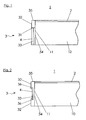
- FIG. 1 shows a furniture board according to the invention 1, which consists of a base plate 10 with an upper decorative layer 2.
- the decor profile 3, which is arranged on the front side 11 of the furniture board 1, has on its side facing away from the end face 11 of the furniture board 1 side at least one element 32 and an offset to this element 33.
- the decorative element 4 is applied on the staggered element 33 of the decorative profile 3.
- the decorative profile 3 was applied to the end face 11 of the furniture board 1 according to the invention after the application of the decorative layer 2 on the base plate 10.
- the elements 32, 33 of the decorative profile 3 are produced by the extrusion process, wherein in this embodiment the staggered element 33 made of a recycled material and the element 32 of the decorative profile 3 are made of a high quality material, for example.
- the decorative element 4 has been heated to a temperature above the activation temperature of the adhesive layer applied to its opposite side to the offset element 33 of the decorative element 4.
- the feeding of the decorative element 4 takes place after the extrusion tool.
- After supplying the decorative element 4 was a cohesive connection between the heated decorative element 4 and the staggered element 33 of the decorative profile 3, wherein in a further process step on the front side 35 and the front side 11 of the furniture board 1 opposite element 32 of the decorative profile 3 a decorative layer applied, which is decor equal to the decorative layer 2 of the furniture board 1.
- the thickness of the decorative element 4 corresponds approximately to the thickness of the step edge 31 of the decorative profile 3.
- the decorative element 4 is arranged with one of its end faces on the step edge 31 of the decorative profile 3.
- a non-inventive furniture board 1 is shown, which is also composed of a base plate 10 and an upper decorative layer 2.
- a decorative profile 3 is arranged, which has the staggered element 33 and two elements 32.
- the elements 32 have on their opposite end faces groove-like recesses 36, in which a decorative element 4 is releasably connectable to the decorative profile 3 .
- the decorative element 4 in this embodiment is designed as a metallic foil, for example, aluminum, wherein the ratio of the thickness of the element 32 of the decorative profile 3 to the thickness of the decorative element 4 in this embodiment is about 7.
- the decorative element 4 is arranged offset to the elements 32.
- the end face 35 of the decorative profile 3 is not executed decor equal to the decorative layer 2 of the furniture board 1, wherein the basic color of the element 32 of the decorative profile 3 in this embodiment corresponds to the basic color of the decorative layer 2 of the furniture board 1.
- FIG. 3 a further embodiment of the furniture board 1 according to the invention is shown, wherein this is composed of a base plate 10 and an upper decorative layer 2.
- a decorative profile 3 is arranged, which has an element 32 and an offset to this element 33.
- decorative elements 4 are at least partially arranged.
- the decorative elements 4 are arranged both to the step edge 31 of the decorative profile 3 as well as to themselves spaced, so that between the decorative elements 4, the staggered element 33 of the decorative profile 3 is visible.
- an adhesive system is applied, by which an integral connection to the furniture board 1 can be realized.
- the decorative profile 3 is produced by a simultaneous extrusion of the element 32 and the offset to this element 33, wherein on the end face 35 and the rear side 34 of the decorative profile 3 opposite side of the element 32, a decorative coating is applied.
- the decorative elements 4 are automatically heated to a temperature above the activation temperature of the applied on the back of the decorative elements 4 adhesive layer and applied cohesively on the recessed element 33 of the decorative profile 3. Thereafter, the decorative profile 3 is applied to the end face 11 of the furniture board 1.
Landscapes
- Engineering & Computer Science (AREA)
- Mechanical Engineering (AREA)
- Life Sciences & Earth Sciences (AREA)
- Wood Science & Technology (AREA)
- Forests & Forestry (AREA)
- Dry Formation Of Fiberboard And The Like (AREA)
- Securing Of Glass Panes Or The Like (AREA)
- Floor Finish (AREA)
- Steam Or Hot-Water Central Heating Systems (AREA)
- Laminated Bodies (AREA)
- Finishing Walls (AREA)
Description
- Die Erfindung betrifft eine Möbelbauplatte, insbesondere eine Küchenarbeitsplatte gemäß dem Oberbegriff des Anspruches 1, sowie ein Verfahren zur Herstellung.
- Eine gattungsgemäße Möbelbauplatte ist aus
DE 200 21 797 U1 bekannt, mit einer Möbelbauplatte mit einer dünnen Nutzschicht als Arbeitsoberfläche, mit einem eine Steinoberfläche nachahmenden Dekor und einem Umleimer vor mindestens einer Stirnseite der Grundplatte mit Nutzschicht, aus einem künstlich erzeugten Steinmaterial. - Aus der
WO 93121027 A1 - Aus der
DE 298 02 242 U1 ist eine Möbelbauplatte bekannt, insbesondere Küchenarbeitsplatte, aus einer Grundplatte mit einer dünnen oberen Deckschicht, insbesondere aus melaminharzgetränktem Papierlaminat und mit einem Umleimer an den Stirnseiten. Diese Möbelbauplatte ist dadurch gekennzeichnet, dass die Grundplatte im Bereich einer Stirnseite unterhalb der Deckschicht eine Hinterfräsung aufweist, die Deckschicht stegartig freigestellt ist und der Umleimer mit seiner Oberseite unmittelbar unterhalb des überstehenden Steges der Deckschicht an diese angrenzend angeordnet ist. Diese Möbelbauplatte weist in der formgefrästen Hinterfräsung nutartige Ausnehmungen auf die für von der Rückseite des Umleimers vorstehende feder- oder stegartige Fortsätze vorgesehen sind. - Die
FR-A-2 739 764 - Die
US-A-5 310 435 offenbart eine Arbeitsplatte mit einem Laminat oder Furnier auf einer horizontalen Fläche und einem Laminat oder Furnier auf einer vertikalen Fläche, wobei ein erstes Eckelement eine bogenförmige Oberfläche aufweist, die bündig in sowohl die horizontale Oberfläche der Arbeitsplatte als auch eine vertikale Oberfläche des Furniers übergeht. Die Arbeitsplatte wird gefertigt, in dem die vertikale Fläche der Platte unvollendet bleibt und der vertikale Furnierstreifen an einem Eckteil angeordnet wird, welches dann an der Kante der Platte angebracht wird. Das Eckteil ist aus einem Blockkörper gefertigt, wobei der vertikale Furnierstreifen an einer der Seiten davon angebracht ist. Nuten werden sowohl oben als unten auf dieser Seite des Blockteils angebracht und Streifen mit rechteckigem Querschnitt, aus welchem die Eckelemente geformt werden, werden in die Nuten eingeklebt. Diese Streifen werden dann bearbeitet, um die weich übergehenden, bogenförmigen Oberflächen zu bilden, die bündig in den Laminatstreifen übergehen. Die Rückseite des Blockteils und die oberseitige Kante des oberen Streifens werden dann bearbeitet, um das Endstück zu bilden, welches mit der Arbeitsplatte zusammenpasst. - Die
US-A-5 525 384 beschreibt ein flexibles Dekorprofil, welches aus einem Kunststoff hergestellt ist, welches über einen Rastfuß mit Rastnasen in einer Nut der Stirnseite der Möbelbauplatte kraftschlüssig einbringbar ist. Das Dekorprofil weist an seiner Oberseite Nuten auf, in die ein flexibler Streifen kraft- bzw. formschlüssig einbringbar ist. Der flexible Streifen kann dabei in verschiedenen Farben ausgebildet sein und so einen unterschiedlichen optischen Gesamteindruck der Möbelbauplatte hervorrufen. Dar flexible Streifen kann weiterhin verschiedene äußere Formen aufweisen und wird durch Krafteinwirkung, bspw. mit einem Gummihammer, in eine Nut an der Oberseite des Dekorprofils eingebracht. - Nachteilig bei diesem vorbekannten Stand der Technik sind zum einen die material- und zeitintensiven Bearbeitungsschritte für die Herstellung der Hinterfräsung in der Grundplatte, wobei es hier zu Beschädigungen der Dekorschicht der Möbelbauplatte kommt. Ein weiterer Nachteil wird darin gesehen, dass die zusätzlich mit einem gleich hohen materiellen bzw. zeitlichem Aufwand in die Grundplatte der Möbelbauplatte einbringbaren nutartigen Ausnehmungen sowohl von ihrer eigentlichen Dimensionierung her als auch von ihrer Position zur Grundplatte bzw. zur Dekorschicht der Möbelbauplatte exakt angeordnet sein müssen, damit die Umleimer passgerecht an die entsprechenden Stirnseiten der Möbelbauplatte anbringbar sind. Hierbei besteht die Gefahr, dass beim Anbringen der Umleimer an die Grundplatte die Dekorschicht der Möbelbauplatte beschädigt sogar abgetrennt wird.
- Ein weiterer Nachteil wird darin gesehen, dass die vorstehenden feder- oder stegartigen Fortsätze der Umleimer und die nutartigen Ausnehmungen der Grundplatte mit einem Klebstoffsystem versehen werden müssen um eine möglichst stoffschlossige Verbindung zu realisieren.
- Neben den hohen Kosten bedingt durch die vielen Verarbeitungsschritte und den hohen zeitlichen Aufwand, die beim Anbringen derartiger Umleimer an die Möbelbauplatte verbunden sind, entspricht auch der realisierte optische Gesamteindruck einer solchen Möbelbauplatte nicht den Anforderungen der Designer und Endkunden.
- Es ist die Aufgabe der vorliegenden Erfindung, eine Möbelbauplatte zur Verfügung zu stellen, die die vorgenannten Nachteile des Standes der Technik überwinden, deren Herstellung vereinfacht und automatisierbar möglich ist, die kostengünstig und wirtschaftlich herstellbar ist und deren optischer Gesamteindruck optimiert ist.
- Die Aufgabe der Erfindung wird in Verbindung mit den Merkmalen des Oberbegriffes erfindungsgemäß durch die kennzeichnenden Merkmale des Anspruches 1 und des Anspruches 16 gelöst.
- Erfindungsgemäss weist das Dekorprofil auf seiner der Stirnseite der Möbelbauplatte abgewandten Seite wenigstens ein Element und ein zu diesem versetzt angeordnetes Element auf und an dem versetzt angeordneten Element ist wenigstens teilweise ein Dekorelement angeordnet. Durch diese Gestaltung der erfindungsgemäßen Möbelbauplatte ist es möglich die Möbelbauplatte kosten günstig herzustellen und automatisiert an die Stirnseiten das Dekorprofil anzubringen.
- Das Dekorelement ist einstückig mit dem versetzt angeordneten Element des Dekorprofiles verbunden.
- Dies kann vorteilhafterweise dadurch realisiert werden, dass auf einer und / oder beiden zu verbindeneden Seiten des Dekorelementes bzw. des versetzt angeordneten Elementes des Dekorprofils ein Klebstoffsystem aufgebracht ist.
Erfindungsgemäss ist das Dekorelement aus einem metallischen Werkstoff ausgeführt, hierdurch ist es möglich, neben den Anforderungen der Designer auch das Dekorprofil an sich so zu dimensionieren, dass die geforderten mechanischen Eigenschaften durch das zusätzlich verstärkende Dekorelement aus einem metallischen Werkstoff realisierbar sind.
In einem Ausführungsbeispiel ist das Dekorelement aus Edelstahl, Aluminium, Kupfer und dergleichen ausgeführt, so dass neben den optischen Anforderungen auch die mechanischen Eigenschaften durch die Art und den Werkstoff des Dekorelementes jederzeit gestaltbar sind.
In einer weiteren vorteilhaften Ausführungsform entspricht die Dicke des Dekorelementes etwa der Dicke der Stufenkante zwischen dem versetzt angeordneten Element und dem an diesen anschließenden Element des Dekorprofiles. Somit lässt sich der optische Gesamteindruck der erfindungsgemäßen Möbelbauplatte vorteilhaft gestalten. - Es liegt aber auch im Rahmen der Erfindung, dass die Dicke des Dekorelementes kleiner und / oder größer als die Dicke der Stufenkante ist, so dass auch das Dekorelement versetzt angeordnet ist.
Es hat sich weiterhin sehr vorteilhaft erwiesen, dass das Dekorelement mit wenigstens einer seiner Stirnseiten an der Stufenkante des Dekorprofiles angeordnet ist. Weiterhin vorteilhaft wird gesehen, dass das Dekorelement mit wenigstens einer seiner Stirnseiten von der Stufenkante des Dekorprofiles beabstandet angeordnet ist. Durch diese Variationsmöglichkeiten können Schattenfugen und dergleichen durch die Designer positioniert werden, wobei gleichzeitig das Herstellungsverfahren derartiger Möbelbauplatten mit an den Stirnseiten befestigbarer Dekorprofile kostengünstig und wirtschaftlich realisierbar ist.
In einer weiteren Ausführungsform steht das Dekorelement in einem Flächenverhältnis von etwa 2 : 1 zur Fläche des nicht versetzt angeordneten Elementes des Dekorprofiles. Durch diese Anordnung kann die Einheitlichkeit der Möbelbauplatte mit ihrer Dekorschicht zu dem Dekorprofil optisch dargestellt werden, wobei das nicht versetzt angeordnete Element des Dekorprofiles in einem weiteren Ausführungsbeispiel dekorgleich zur Dekorschicht der erfindungsgemäßen Möbelbauplatte ist.
Überraschend wurde gefunden, dass bei einem Verhältnis der Dicke des nicht versetzt angeordneten Elementes des Dekorprofiles zur Dicke des Dekorelementes von wenigstens 1, die Herstellungskosten, sowie die Festigkeits- bzw. die Stabilitätseigenschaften und das Design der Möbelbauplatten mit an den Stirnseiten befestigbarer Dekorprofile optimal in Einklang gebracht werden können.
Es hat sich weiterhin als sehr vorteilhaft erwiesen, dass die Grundfarbe des versetzt angeordneten und des nicht versetzt angeordneten Elementes des Dekorprofiles der Grundfarbe der Dekorschicht der Möbelbauplatte entspricht. Dadurch kann der sogenannte Bilderrahmeneffekt verhindert werden.
Ebenso vorteilhaft erweist sich die Tatsache, dass die Stirnseite des Dekorprofiles dekorgleich zur Dekorschicht der erfindungsgemäßen Möbelbauplatte ist. In den Werkstoffen der Elemente des Dekorprofiles könne zusätzlich Füllstoffe wie beispielsweise Pigmente, Flitter und dergleichen eingebracht sein, die damit das gleiche Dekor wie die Dekorschicht der Möbelbauplatte aufweisen. - Durch das auf die Rückseite des Dekorprofiles, welche der Stirnseite der Möbelbauplatte zugeordnet ist, aufgebrachte Klebstoffsystem kann das Dekorprofil im automatisierten Betrieb kostengünstig und schnell an die Stirnseite der erfindungsgemäßen Möbelbauplatte stoffschlüssig aufgebracht werden.
Es hat sich überraschend gezeigt, dass das Verhältnis der thermischen Ausdehnungskoeffizienten des Dekorelementes zu dem des versetzt angeordneten Elementes des Dekorprofiles wenigstens 10 ist, da hierdurch vorteilhafterweise zum einen die geforderte Stabilität und Festigkeit des an die erfindungsgemäße Möbelbauplatte angeordneten Dekorprofiles realisierbar ist, andererseits aber auch verschieden große bzw. kleine Biegeradien, welche beispielsweise bei abgerundeten Möbelbauplatten erforderlich sind, entsprechend kostengünstig umsetzbar sind.
Das Verfahren zur Herstellung einer Möbelbauplatte mit Dekorprofil, insbesondere Küchenarbeitsplatte ist gekennzeichnet durch die folgenden Schritte: - Extrusion der Elemente des Dekorprofiles
- Zuführung des Dekorelementes
- Stoffschlüssiges Verbinden des Dekorelementes mit dem Element des Dekorprofils, wobei das Element eine Temperatur oberhalb seiner Erweichungstemperatur aufweist.
- Abkühlen des mit dem Dekorelement stoffschlüssig verbundenen Elementes des Dekorprofiles.
- Aufbringen einer Dekorschicht auf dem Element des Dekorprofiles.
- Abtrocknen und Aufwickeln des Dekorprofiles.
- Anbringen des Dekorprofils an die Stirnseite der Möbelbauplatte.
- Nachfolgend soll der Gegenstand der Erfindung an weiteren vorteilhaften Ausführungsformen beschrieben werden, die jedoch den Gegenstand der Erfindung nicht einschränken.
Es zeigen: - Fig. 1
- eine Möbelbauplatte mit einem Dekorprofil
- Fig. 2
- eine Möbelbauplatte mit einem Dekorprofil
- Fig. 3
- eine Möbelbauplatte mit einem Dekorprofil
-
Figur 1 zeigt eine erfindungsgemäße Möbelbauplatte 1, welche aus einer Grundplatte 10 mit einer oberen Dekorschicht 2 besteht. Das Dekorprofil 3 welches an der Stirnseite 11 der Möbelbauplatte 1 angeordnet ist, weist auf seiner der Stirnseite 11 der Möbelbauplatte 1 abgewandten Seite wenigstens ein Element 32 und ein zu diesem versetzt angeordnetes Element 33 auf. Auf dem versetzt angeordneten Element 33 des Dekorprofiles 3 ist das Dekorelement 4 aufgebracht. In diesem Ausführungsbeispiel wurde an die Stirnseite 11 der erfindungsgemäßen Möbelbauplatte 1 nach dem Aufbringen der Dekorschicht 2 auf die Grundplatte 10 das Dekorprofil 3 aufgebracht. Die Elemente 32, 33 des Dekorprofiles 3 werden durch das Extrusionsverfahren hergestellt, wobei in diesem Ausführungsbeispiel das versetzt angeordnete Element 33 aus einem recycelten Werkstoff und das Element 32 des Dekorprofiles 3 aus einem hochwertigem Werkstoff bspw. im Koextrusionsverfahren hergestellt werden. Das Dekorelement 4 wurde auf eine Temperatur oberhalb der Aktivierungstemperatur der auf seiner dem versetzt angeordneten Element 33 des Dekorelementes 4 gegenüberliegenden Seite angebrachten Klebstoffschicht erhitzt. Das Zuführen des Dekorelementes 4 erfolgt nach dem Extrusionswerkzeug. Nach dem Zuführen des Dekorelementes 4 erfolgte eine stoffschlüssige Verbindung zwischen dem erhitzten Dekorelement 4 und dem versetzt angeordneten Element 33 des Dekorprofiles 3, wobei in einem weiteren Verfahrensschritt auf die Stirnseite 35 und das der Stirnseite 11 der Möbelbauplatte 1 gegenüberliegende Element 32 des Dekorprofiles 3 eine Dekorschicht aufgebracht, welche dekorgleich zur Dekorschicht 2 der Möbelbauplatte 1 ist. - Auf die Rückseite 34 des Dekorelementes 3, welche der Stirnfläche 11 der Möbelbauplatte 1 gegenüberliegend angeordnet ist, wurde ein Klebstoffsystem aufgebracht, so dass das Dekorprofil 3 stoffschlüssig mit der Möbelbauplatte 1 verbindbar ist.
In diesem Ausführungsbeispiel entspricht die Dicke des Dekorelementes 4 etwa der Dicke der Stufenkante 31 des Dekorprofiles 3. Das Dekorelement 4 ist mit einer seiner Stirnseiten an der Stufenkante 31 des Dekorprofiles 3 angeordnet. - In
Figur 2 ist eine nicht erfindungsgemäßeMöbelbauplatte 1 dargestellt, wobei diese ebenfalls aus einer Grundplatte 10 und einer oberen Dekorschicht 2 aufgebaut ist. An der Stirnseite 11 der Möbelbauplatte 1 ist ein Dekorprofil 3 angeordnet, welches das versetzt angeordnete Element 33 aufweist und zwei Elemente 32. Die Elemente 32 weisen an ihren gegenüberliegenden Stirnseiten nutartige Ausnehmungen 36 auf, in die ein Dekorelement 4 lösbar mit dem Dekorprofil 3 verbindbar ist. Das Dekorelement 4 in diesem Ausführungsbeispiel ist als metallische Folie aus beispielsweise Aluminium ausgeführt, wobei das Verhältnis der Dicke des Elementes 32 des Dekorprofiles 3 zur Dicke des Dekorelementes 4 in diesem Ausführungsbeispiel etwa 7 ist. Das Dekorelement 4 ist zu den Elementen 32 versetzt angeordnet. Die Stirnseite 35 des Dekorprofiles 3 ist nicht dekorgleich zur Dekorschicht 2 der Möbelbauplatte 1 ausgeführt, wobei die Grundfarbe des Elementes 32 des Dekorprofiles 3 in diesem Ausführungsbeispiel der Grundfarbe der Dekorschicht 2 der Möbelbauplatte 1 entspricht. - In
Figur 3 ist eine weitere Ausführungsform der erfindungsgemäßen Möbelbauplatte 1 dargestellt, wobei diese aus einer Grundplatte 10 und einer oberen Dekorschicht 2 aufgebaut ist. An der Stirnseite 11 der Möbelbauplatte 1 ist ein Dekorprofil 3 angeordnet, welches ein Element 32 und ein zu diesem versetzt angeordnetes Element 33 aufweist. An der der Stirnseite 35 des Dekorprofiles 3 gegenüberliegenden Stufenkante 31 sind wenigstens teilweise Dekorelemente 4 angeordnet. In diesem Ausführungsbeispiel sind die Dekorelemente 4 sowohl zur Stufenkante 31 des Dekorprofiles 3 als auch zu sich selbst beabstandet angeordnet, so dass zwischen den Dekorelementen 4 das versetzt angeordnete Element 33 des Dekorprofiles 3 sichtbar ist. Auf der Rückseite 34 des Dekorprofiles 3 ist ein Klebstoffsystem aufgebracht, durch welches eine einstückige Verbindung zu der Möbelbauplatte 1 realisierbar ist. - Das Dekorprofil 3 wird durch eine gleichzeitige Extrusion des Elementes 32 und dem zu diesem versetzt angeordneten Element 33 hergestellt, wobei auf die Stirnfläche 35 und die der Rückseite 34 des Dekorprofiles 3 gegenüberliegende Seite des Elementes 32 eine Dekorbeschichtung aufgebracht wird. In einem weiteren Verfahrensschritt werden die Dekorelemente 4 automatisiert auf eine Temperatur oberhalb der Aktivierungstemperatur der auf der Rückseite der Dekorelemente 4 aufgebrachten Klebstoffschicht erhitzt und auf dem zurückgesetzten Element 33 des Dekorprofiles 3 stoffschlüssig aufgebracht. Danach wird das Dekorpfofil 3 an die Stirnseite 11 der Möbelbauplatte 1 aufgebracht.
Weiterhin vorteilhaft wird gesehen, dass auf die Oberseite und / oder die Unterseite des Dekorelementes bzw. dass auf die Oberseite und / oder die Unterseite der Elemente des Dekorprofils eine Prägung aufgebracht wird.
Mit dem erfindungsgemäßen Verfahren ist möglich, dass das Dekorelement in das Extrusionswerkzeug bzw. nach dem Extrusionswerkzeug zugeführt wird.
Claims (22)
- Möbelbauplatte (1), insbesondere Küchenarbeitsplatte, aus einer Grundplatte (10) mit einer oberen Dekorschicht (2) und einem Dekorprofil (3), das mit seiner ebenen Rückseite (34) stoffschlüssig an den Stirnseiten (11) der Möbelbauplatte (1) angebracht ist, wobei das Dekorprofil (3) mit einer Oberseite und mit einer Unterseite der Möbelbauplatte (1) bündig abschließt und auf seiner der Stirnseite (11) der Möbelbauplatte (1) abgewandten Seite wenigstens ein Element (32) und ein zu diesem versetzt angeordnetes Element (33) aufweist, dadurch gekennzeichnet, dass auf wenigstens einem dieser Elemente (32, 33) wenigstens teilweise ein Dekorelement (4) angeordnet ist, dass das Dekorelement (4) einstückig mit dem Element (33) des Dekorprofils (3) verbunden ist, wobei das Dekorelement (4) aus einem metallischem Werkstoff ausgeführt ist.
- Möbelbauplatte nach Anspruch 1, dadurch gekennzeichnet, dass das Dekorelement (4) aus Edelstahl, Aluminium, Kupfer und dergleichen ausgeführt ist.
- Möbelbauplatte nach einem der vorhergehenden Ansprüche, dadurch gekennzeichnet, dass das Dekorelement (4) als Metallfolie ausgeführt ist.
- Möbelbauplatte nach einem der vorhergehenden Ansprüche, dadurch gekennzeichnet, dass das Dekorelement (4) mit wenigstens einer seiner Stirnseiten an der Stufenkante (31) des Dekorprofiles (3) angeordnet ist.
- Möbelbauplatte nach einem der vorhergehenden Ansprüche, dadurch gekennzeichnet, dass das Dekorelement (4) mit wenigstens einer seiner Stirnseiten von der Stufenkante (31) des Dekorprofiles (3) beabstandet angeordnet ist.
- Möbelbauplatte nach einem der vorhergehenden Ansprüche, dadurch gekennzeichnet, dass die Dicke des Dekorelementes (4) etwa der Dicke einer Stufenkante (31) des Dekorprofiles (3) entspricht.
- Möbelbauplatte nach einem der vorhergehenden Ansprüche, dadurch gekennzeichnet, dass die Dicke des Dekorelementes (4) kleiner als die Dicke der Stufenkante (31) des Dekorprofiles (3) ist.
- Möbelbauplatte nach einem der vorhergehenden Ansprüche, dadurch gekennzeichnet, dass die Dicke des Dekorelementes (4) größer als die Dicke der Stufenkante (31) des Dekorprofiles (3) ist.
- Möbelbauplatte nach einem der vorhergehenden Ansprüche, dadurch gekennzeichnet, dass das Dekorelement (4) in einem Flächenverhältnis von etwa 2 : 1 zur Fläche des Elementes (32) des Dekorprofiles (3) steht.
- Möbelbauplatte nach einem der vorhergehenden Ansprüche, dadurch gekennzeichnet, dass das Verhältnis der Dicke des Elementes (32) des Dekorprofiles (3) zur Dicke des Dekorelementes (4) wenigstens 1 ist.
- Möbelbauplatte nach einem der vorhergehenden Ansprüche, dadurch gekennzeichnet, dass das Element (32) des Dekorprofiles (3) dekorgleich zur Dekorschicht (2) der Möbelbauplatte (1) ist.
- Möbelbauplatte nach einem der vorhergehenden Ansprüche, dadurch gekennzeichnet, dass die Grundfarbe des Elementes (32, 33) des Dekorprofiles (3) der Grundfarbe der Dekorschicht (2) der Möbelbauplatte (1) entspricht.
- Möbelbauplatte nach einem der vorhergehenden Ansprüche, dadurch gekennzeichnet, dass die Stirnseite (35) des Dekorprofiles (3) dekorgleich zur Dekorschicht (2) der Möbelbauplatte (1) ist.
- Möbelbauplatte nach einem der vorhergehenden Ansprüche, dadurch gekennzeichnet, dass die der Stirnseite (11) der Möbelbauplatte (1) zugewandte Rückseite (34) des Dekorprofiles (3) wenigstens teilweise ein Klebstoffsystem aufweist.
- Möbelbauplatte nach einem der vorhergehenden Ansprüche, dadurch gekennzeichnet, dass das Verhältnis der thermischen Ausdehnungskoeffizienten des Dekorelementes (4) zu dem des Elementes (32, 33) des Dekorprofiles (3) wenigstens 10 ist.
- Verfahren zur Herstellung einer Möbelbauplatte mit Dekorprofil, insbesondere Küchenarbeitsplatte, gekennzeichnet durch die folgenden Schritte:• Extrusion der Elemente (32, 33),• Zuführung des Dekorelementes (4),• Verbinden des Dekorelementes (4) mit dem Element (32, 33) des Dekorprofils (3), wobei das Element (32, 33) eine Temperatur oberhalb seiner Erweichungstemperatur aufweist,• Abkühlen des mit dem Dekorelement (4) verbundenen Elementes (32, 33) des Dekorprofiles (3),• Aufbringen einer Dekorschicht auf dem Element (32, 33) des Dekorprofiles (3),• Abtrocknen und Aufwickeln des Dekorprofiles (3),• Anbringen des Dekorprofils (3) an die Stirnseite (11) der Möbelbauplatte (1).
- Verfahren nach Anspruch 16, dadurch gekennzeichnet, dass das Dekorelement (4) vor dem Zuführen erhitzt wird.
- Verfahren nach Anspruch 16, dadurch gekennzeichnet, dass auf das Dekorelement (4) an seiner dem Element (32, 33) des Dekorprofils (3) zugewandten Seite wenigstens teilweise ein Klebstoffsystem aufgebracht wird.
- Verfahren nach Anspruch 16, dadurch gekennzeichnet, dass auf die dem Dekorelement (4) zugeordnete Seite des Elementes (32, 33) des Dekorprofils (3) wenigstens teilweise ein Klebstoffsystem aufgebracht wird.
- Verfahren nach einem der Ansprüche 16 bis 19, dadurch gekennzeichnet, dass das Dekorelement (4) auf eine Temperatur oberhalb der Aktivierungstemperatur des Klebstoffsystems erhitzt wird.
- Verfahren nach einem der Ansprüche 16 bis 20, dadurch gekennzeichnet, dass das Dekorelement (4) in das Extrusionswerkzeug zugeführt wird.
- Verfahren nach einem der Ansprüche 16 bis 21, dadurch gekennzeichnet, dass das Dekorelement (4) nach dem Extrusionswerkzeug zugeführt wird.
Priority Applications (2)
| Application Number | Priority Date | Filing Date | Title |
|---|---|---|---|
| PL04010267T PL1479320T3 (pl) | 2003-05-21 | 2004-04-30 | Meblowa płyta konstrukcyjna |
| SI200431907T SI1479320T1 (sl) | 2003-05-21 | 2004-04-30 | Pohištvena konstrukcijska plošča |
Applications Claiming Priority (2)
| Application Number | Priority Date | Filing Date | Title |
|---|---|---|---|
| DE10323455 | 2003-05-21 | ||
| DE10323455A DE10323455A1 (de) | 2003-05-21 | 2003-05-21 | Möbelbauplatte |
Publications (2)
| Publication Number | Publication Date |
|---|---|
| EP1479320A1 EP1479320A1 (de) | 2004-11-24 |
| EP1479320B1 true EP1479320B1 (de) | 2012-05-09 |
Family
ID=33039302
Family Applications (1)
| Application Number | Title | Priority Date | Filing Date |
|---|---|---|---|
| EP04010267A Expired - Lifetime EP1479320B1 (de) | 2003-05-21 | 2004-04-30 | Möbelbauplatte |
Country Status (6)
| Country | Link |
|---|---|
| EP (1) | EP1479320B1 (de) |
| AT (1) | ATE556621T1 (de) |
| DE (1) | DE10323455A1 (de) |
| PL (1) | PL1479320T3 (de) |
| PT (1) | PT1479320E (de) |
| SI (1) | SI1479320T1 (de) |
Families Citing this family (3)
| Publication number | Priority date | Publication date | Assignee | Title |
|---|---|---|---|---|
| DE102006006611A1 (de) * | 2006-02-14 | 2007-09-20 | Rehau Ag + Co | Verfahren zur Herstellung einer Profilleiste |
| DE102016109362A1 (de) * | 2016-05-20 | 2017-11-23 | Fritz Egger Gmbh & Co. Og | Vorrichtung und Verfahren zum Anbringen eines Kantenprofils sowie Möbelteil |
| DE102024124664A1 (de) * | 2024-08-29 | 2026-03-05 | REHAU Industries SE & Co. KG | Verfahren zur Schmalflächenbeschichtung von Plattenelementen |
Citations (5)
| Publication number | Priority date | Publication date | Assignee | Title |
|---|---|---|---|---|
| US2030730A (en) * | 1935-05-23 | 1936-02-11 | Walter E Wilson | Molding strip |
| GB2246701A (en) * | 1990-08-09 | 1992-02-12 | Bushboard Parker Ltd | Work top edge trim |
| WO1993021027A1 (en) * | 1992-04-22 | 1993-10-28 | Herman Miller, Inc. | Work surface with a flexible edge |
| US5310435A (en) * | 1989-11-13 | 1994-05-10 | Kelly Basil T | Method for making corners for laminate and veneer countertops |
| FR2739764A1 (fr) * | 1995-10-17 | 1997-04-18 | Mullerhof | Plateau de table et procede de fixation d'un profile sur le chant d'un tel plateau |
Family Cites Families (5)
| Publication number | Priority date | Publication date | Assignee | Title |
|---|---|---|---|---|
| DE1242355B (de) * | 1963-10-19 | 1967-06-15 | Schock & Co Gmbh | Verfahren zum Herstellen von mehrteiligen Schichtleisten |
| US4446179A (en) * | 1982-05-21 | 1984-05-01 | The D. L. Auld Company | Trim strip for automobile bodies |
| US5525384A (en) | 1995-01-12 | 1996-06-11 | Woodland Holding Corporation | Flexible molding strip having inserted decorative cord and furniture provided with such strips |
| DE29802242U1 (de) | 1998-02-10 | 1998-04-16 | Danielmeyer Guenter | Möbelbauplatte |
| DE20021797U1 (de) | 2000-12-22 | 2001-05-03 | Danielmeyer, Günter, 32584 Löhne | Möbelbauplatte |
-
2003
- 2003-05-21 DE DE10323455A patent/DE10323455A1/de not_active Ceased
-
2004
- 2004-04-30 PT PT04010267T patent/PT1479320E/pt unknown
- 2004-04-30 SI SI200431907T patent/SI1479320T1/sl unknown
- 2004-04-30 AT AT04010267T patent/ATE556621T1/de active
- 2004-04-30 EP EP04010267A patent/EP1479320B1/de not_active Expired - Lifetime
- 2004-04-30 PL PL04010267T patent/PL1479320T3/pl unknown
Patent Citations (5)
| Publication number | Priority date | Publication date | Assignee | Title |
|---|---|---|---|---|
| US2030730A (en) * | 1935-05-23 | 1936-02-11 | Walter E Wilson | Molding strip |
| US5310435A (en) * | 1989-11-13 | 1994-05-10 | Kelly Basil T | Method for making corners for laminate and veneer countertops |
| GB2246701A (en) * | 1990-08-09 | 1992-02-12 | Bushboard Parker Ltd | Work top edge trim |
| WO1993021027A1 (en) * | 1992-04-22 | 1993-10-28 | Herman Miller, Inc. | Work surface with a flexible edge |
| FR2739764A1 (fr) * | 1995-10-17 | 1997-04-18 | Mullerhof | Plateau de table et procede de fixation d'un profile sur le chant d'un tel plateau |
Also Published As
| Publication number | Publication date |
|---|---|
| PT1479320E (pt) | 2012-08-10 |
| ATE556621T1 (de) | 2012-05-15 |
| SI1479320T1 (sl) | 2012-09-28 |
| EP1479320A1 (de) | 2004-11-24 |
| PL1479320T3 (pl) | 2012-10-31 |
| DE10323455A1 (de) | 2004-12-30 |
Similar Documents
| Publication | Publication Date | Title |
|---|---|---|
| DE69312927T2 (de) | Platte und verfahren zu ihrer herstellung | |
| EP0857442A2 (de) | Verfahren zum Herstellen einer Profilleiste, insbesondere einer Kantenleiste für die Möbelindustrie | |
| DE202014102150U1 (de) | Dachrelinganordnung für ein Kraftfahrzeug | |
| DE202007014991U1 (de) | Kantenleiste für Möbelstücke | |
| EP2015652B1 (de) | Zusatzelement für ein möbelteil aus einer leichtbauplatte, möbelteil und möbel | |
| EP2016237B1 (de) | Abdichtungselement für eine leichtbauplatte | |
| DE19607051C2 (de) | Verfahren zum Herstellen einer Holzfurnier-Garnitur für die dekorative Innenausstattung eines Kraftfahrzeugs | |
| EP1984191B1 (de) | Verfahren zur herstellung einer profilleiste | |
| DE3906594A1 (de) | Verfahren zur herstellung eines postforming-laminats | |
| DE102015119148A1 (de) | Leistenanordnung mit Verbindungselementen | |
| EP1683929B1 (de) | Verfahren zur Herstellung eines Paneels, insbesondere Fussbodenpaneels, und Paneel, insbesondere Fussbodenpaneel | |
| EP1587694B2 (de) | Mehrlagiges dekorband mit einer reliefstruktur und einer aluminiumschicht und verfahren zu dessen herstellung | |
| DE102006038115B4 (de) | Leichtbauplatte und Verfahren zu deren Herstellung | |
| EP4007510A1 (de) | Kantenleiste | |
| EP1871626A1 (de) | Abdeckung an einem kraftfahrzeugaussenteil sowie entsprechendes verfahren zur herstellung und entsprechende verwendung | |
| EP1479320A1 (de) | Möbelbauplatte | |
| DE20016842U1 (de) | Profilleiste, insbesondere Kantenleiste für die Möbelindustrie | |
| EP1867796B1 (de) | Verbundplatte für den Innenausbau | |
| DE102008035012A1 (de) | Leichtbauplatte für den Möbelbau | |
| DE19707857C2 (de) | Rahmen für ein Kochfeld | |
| EP2505325B1 (de) | Verfahren zum Anbringen von Kantenstreifen an einem plattenförmigen Verbundformteil | |
| DE19615769C1 (de) | Rahmen für ein Kochfeld | |
| DE10355361B4 (de) | Verfahren zur Herstellung einer Deckschicht, Deckschicht und Möbelplatte mit einer Deckschicht | |
| DE20308118U1 (de) | Möbelbauplatte | |
| DE102020003996A1 (de) | Wandsystem, Wandelement und Träger bzw. Verbinder |
Legal Events
| Date | Code | Title | Description |
|---|---|---|---|
| PUAI | Public reference made under article 153(3) epc to a published international application that has entered the european phase |
Free format text: ORIGINAL CODE: 0009012 |
|
| AK | Designated contracting states |
Kind code of ref document: A1 Designated state(s): AT BE BG CH CY CZ DE DK EE ES FI FR GB GR HU IE IT LI LU MC NL PL PT RO SE SI SK TR |
|
| AX | Request for extension of the european patent |
Extension state: AL HR LT LV MK |
|
| 17P | Request for examination filed |
Effective date: 20041230 |
|
| AKX | Designation fees paid |
Designated state(s): AT BE BG CH CY CZ DE DK EE ES FI FR GB GR HU IE IT LI LU MC NL PL PT RO SE SI SK TR |
|
| AXX | Extension fees paid |
Extension state: HR Payment date: 20041230 Extension state: LT Payment date: 20041230 Extension state: LV Payment date: 20041230 |
|
| 17Q | First examination report despatched |
Effective date: 20061206 |
|
| 17Q | First examination report despatched |
Effective date: 20061206 |
|
| GRAP | Despatch of communication of intention to grant a patent |
Free format text: ORIGINAL CODE: EPIDOSNIGR1 |
|
| GRAS | Grant fee paid |
Free format text: ORIGINAL CODE: EPIDOSNIGR3 |
|
| GRAA | (expected) grant |
Free format text: ORIGINAL CODE: 0009210 |
|
| AK | Designated contracting states |
Kind code of ref document: B1 Designated state(s): AT BE BG CH CY CZ DE DK EE ES FI FR GB GR HU IE IT LI LU MC NL PL PT RO SE SI SK TR |
|
| AX | Request for extension of the european patent |
Extension state: HR LT LV |
|
| REG | Reference to a national code |
Ref country code: GB Ref legal event code: FG4D Free format text: NOT ENGLISH |
|
| REG | Reference to a national code |
Ref country code: CH Ref legal event code: EP Ref country code: AT Ref legal event code: REF Ref document number: 556621 Country of ref document: AT Kind code of ref document: T Effective date: 20120515 |
|
| REG | Reference to a national code |
Ref country code: IE Ref legal event code: FG4D Free format text: LANGUAGE OF EP DOCUMENT: GERMAN |
|
| REG | Reference to a national code |
Ref country code: DE Ref legal event code: R096 Ref document number: 502004013496 Country of ref document: DE Effective date: 20120712 |
|
| REG | Reference to a national code |
Ref country code: SE Ref legal event code: TRGR |
|
| REG | Reference to a national code |
Ref country code: PT Ref legal event code: SC4A Free format text: AVAILABILITY OF NATIONAL TRANSLATION Effective date: 20120801 |
|
| REG | Reference to a national code |
Ref country code: NL Ref legal event code: VDEP Effective date: 20120509 |
|
| REG | Reference to a national code |
Ref country code: LT Ref legal event code: MG9D Effective date: 20120523 |
|
| PG25 | Lapsed in a contracting state [announced via postgrant information from national office to epo] |
Ref country code: FI Free format text: LAPSE BECAUSE OF FAILURE TO SUBMIT A TRANSLATION OF THE DESCRIPTION OR TO PAY THE FEE WITHIN THE PRESCRIBED TIME-LIMIT Effective date: 20120509 Ref country code: CY Free format text: LAPSE BECAUSE OF FAILURE TO SUBMIT A TRANSLATION OF THE DESCRIPTION OR TO PAY THE FEE WITHIN THE PRESCRIBED TIME-LIMIT Effective date: 20120509 |
|
| REG | Reference to a national code |
Ref country code: PL Ref legal event code: T3 |
|
| REG | Reference to a national code |
Ref country code: SK Ref legal event code: T3 Ref document number: E 12315 Country of ref document: SK |
|
| PG25 | Lapsed in a contracting state [announced via postgrant information from national office to epo] |
Ref country code: GR Free format text: LAPSE BECAUSE OF FAILURE TO SUBMIT A TRANSLATION OF THE DESCRIPTION OR TO PAY THE FEE WITHIN THE PRESCRIBED TIME-LIMIT Effective date: 20120810 |
|
| PG25 | Lapsed in a contracting state [announced via postgrant information from national office to epo] |
Ref country code: EE Free format text: LAPSE BECAUSE OF FAILURE TO SUBMIT A TRANSLATION OF THE DESCRIPTION OR TO PAY THE FEE WITHIN THE PRESCRIBED TIME-LIMIT Effective date: 20120509 Ref country code: CZ Free format text: LAPSE BECAUSE OF FAILURE TO SUBMIT A TRANSLATION OF THE DESCRIPTION OR TO PAY THE FEE WITHIN THE PRESCRIBED TIME-LIMIT Effective date: 20120509 Ref country code: RO Free format text: LAPSE BECAUSE OF FAILURE TO SUBMIT A TRANSLATION OF THE DESCRIPTION OR TO PAY THE FEE WITHIN THE PRESCRIBED TIME-LIMIT Effective date: 20120509 Ref country code: NL Free format text: LAPSE BECAUSE OF FAILURE TO SUBMIT A TRANSLATION OF THE DESCRIPTION OR TO PAY THE FEE WITHIN THE PRESCRIBED TIME-LIMIT Effective date: 20120509 Ref country code: DK Free format text: LAPSE BECAUSE OF FAILURE TO SUBMIT A TRANSLATION OF THE DESCRIPTION OR TO PAY THE FEE WITHIN THE PRESCRIBED TIME-LIMIT Effective date: 20120509 |
|
| PLBE | No opposition filed within time limit |
Free format text: ORIGINAL CODE: 0009261 |
|
| STAA | Information on the status of an ep patent application or granted ep patent |
Free format text: STATUS: NO OPPOSITION FILED WITHIN TIME LIMIT |
|
| 26N | No opposition filed |
Effective date: 20130212 |
|
| PG25 | Lapsed in a contracting state [announced via postgrant information from national office to epo] |
Ref country code: ES Free format text: LAPSE BECAUSE OF FAILURE TO SUBMIT A TRANSLATION OF THE DESCRIPTION OR TO PAY THE FEE WITHIN THE PRESCRIBED TIME-LIMIT Effective date: 20120820 |
|
| REG | Reference to a national code |
Ref country code: DE Ref legal event code: R097 Ref document number: 502004013496 Country of ref document: DE Effective date: 20130212 |
|
| PG25 | Lapsed in a contracting state [announced via postgrant information from national office to epo] |
Ref country code: BG Free format text: LAPSE BECAUSE OF FAILURE TO SUBMIT A TRANSLATION OF THE DESCRIPTION OR TO PAY THE FEE WITHIN THE PRESCRIBED TIME-LIMIT Effective date: 20120809 |
|
| BERE | Be: lapsed |
Owner name: REHAU A.G. + CO Effective date: 20130430 |
|
| PG25 | Lapsed in a contracting state [announced via postgrant information from national office to epo] |
Ref country code: MC Free format text: LAPSE BECAUSE OF FAILURE TO SUBMIT A TRANSLATION OF THE DESCRIPTION OR TO PAY THE FEE WITHIN THE PRESCRIBED TIME-LIMIT Effective date: 20120509 |
|
| REG | Reference to a national code |
Ref country code: IE Ref legal event code: MM4A |
|
| PG25 | Lapsed in a contracting state [announced via postgrant information from national office to epo] |
Ref country code: BE Free format text: LAPSE BECAUSE OF NON-PAYMENT OF DUE FEES Effective date: 20130430 |
|
| PG25 | Lapsed in a contracting state [announced via postgrant information from national office to epo] |
Ref country code: IE Free format text: LAPSE BECAUSE OF NON-PAYMENT OF DUE FEES Effective date: 20130430 |
|
| PGFP | Annual fee paid to national office [announced via postgrant information from national office to epo] |
Ref country code: SK Payment date: 20140317 Year of fee payment: 11 |
|
| PGFP | Annual fee paid to national office [announced via postgrant information from national office to epo] |
Ref country code: GB Payment date: 20140410 Year of fee payment: 11 |
|
| PGFP | Annual fee paid to national office [announced via postgrant information from national office to epo] |
Ref country code: AT Payment date: 20140407 Year of fee payment: 11 Ref country code: CH Payment date: 20140408 Year of fee payment: 11 Ref country code: SI Payment date: 20140314 Year of fee payment: 11 |
|
| REG | Reference to a national code |
Ref country code: FR Ref legal event code: PLFP Year of fee payment: 12 |
|
| PG25 | Lapsed in a contracting state [announced via postgrant information from national office to epo] |
Ref country code: HU Free format text: LAPSE BECAUSE OF FAILURE TO SUBMIT A TRANSLATION OF THE DESCRIPTION OR TO PAY THE FEE WITHIN THE PRESCRIBED TIME-LIMIT; INVALID AB INITIO Effective date: 20040430 Ref country code: LU Free format text: LAPSE BECAUSE OF NON-PAYMENT OF DUE FEES Effective date: 20130430 |
|
| PGFP | Annual fee paid to national office [announced via postgrant information from national office to epo] |
Ref country code: SE Payment date: 20150429 Year of fee payment: 12 |
|
| PGFP | Annual fee paid to national office [announced via postgrant information from national office to epo] |
Ref country code: FR Payment date: 20150428 Year of fee payment: 12 |
|
| REG | Reference to a national code |
Ref country code: CH Ref legal event code: PL |
|
| REG | Reference to a national code |
Ref country code: AT Ref legal event code: MM01 Ref document number: 556621 Country of ref document: AT Kind code of ref document: T Effective date: 20150430 |
|
| GBPC | Gb: european patent ceased through non-payment of renewal fee |
Effective date: 20150430 |
|
| REG | Reference to a national code |
Ref country code: SK Ref legal event code: MM4A Ref document number: E 12315 Country of ref document: SK Effective date: 20150430 |
|
| PG25 | Lapsed in a contracting state [announced via postgrant information from national office to epo] |
Ref country code: GB Free format text: LAPSE BECAUSE OF NON-PAYMENT OF DUE FEES Effective date: 20150430 Ref country code: LI Free format text: LAPSE BECAUSE OF NON-PAYMENT OF DUE FEES Effective date: 20150430 Ref country code: CH Free format text: LAPSE BECAUSE OF NON-PAYMENT OF DUE FEES Effective date: 20150430 |
|
| REG | Reference to a national code |
Ref country code: SI Ref legal event code: KO00 Effective date: 20151215 |
|
| PG25 | Lapsed in a contracting state [announced via postgrant information from national office to epo] |
Ref country code: SK Free format text: LAPSE BECAUSE OF NON-PAYMENT OF DUE FEES Effective date: 20150430 Ref country code: AT Free format text: LAPSE BECAUSE OF NON-PAYMENT OF DUE FEES Effective date: 20150430 Ref country code: SI Free format text: LAPSE BECAUSE OF NON-PAYMENT OF DUE FEES Effective date: 20150501 |
|
| PGFP | Annual fee paid to national office [announced via postgrant information from national office to epo] |
Ref country code: PL Payment date: 20160310 Year of fee payment: 13 |
|
| PGFP | Annual fee paid to national office [announced via postgrant information from national office to epo] |
Ref country code: IT Payment date: 20160330 Year of fee payment: 13 Ref country code: PT Payment date: 20160502 Year of fee payment: 13 |
|
| REG | Reference to a national code |
Ref country code: FR Ref legal event code: ST Effective date: 20161230 |
|
| PG25 | Lapsed in a contracting state [announced via postgrant information from national office to epo] |
Ref country code: FR Free format text: LAPSE BECAUSE OF NON-PAYMENT OF DUE FEES Effective date: 20160502 |
|
| PG25 | Lapsed in a contracting state [announced via postgrant information from national office to epo] |
Ref country code: SE Free format text: LAPSE BECAUSE OF NON-PAYMENT OF DUE FEES Effective date: 20160501 |
|
| PG25 | Lapsed in a contracting state [announced via postgrant information from national office to epo] |
Ref country code: PT Free format text: LAPSE BECAUSE OF NON-PAYMENT OF DUE FEES Effective date: 20171031 |
|
| PG25 | Lapsed in a contracting state [announced via postgrant information from national office to epo] |
Ref country code: IT Free format text: LAPSE BECAUSE OF NON-PAYMENT OF DUE FEES Effective date: 20170430 |
|
| PG25 | Lapsed in a contracting state [announced via postgrant information from national office to epo] |
Ref country code: PL Free format text: LAPSE BECAUSE OF NON-PAYMENT OF DUE FEES Effective date: 20170430 |
|
| PGFP | Annual fee paid to national office [announced via postgrant information from national office to epo] |
Ref country code: DE Payment date: 20190430 Year of fee payment: 16 |
|
| PGFP | Annual fee paid to national office [announced via postgrant information from national office to epo] |
Ref country code: TR Payment date: 20190418 Year of fee payment: 16 |
|
| REG | Reference to a national code |
Ref country code: DE Ref legal event code: R119 Ref document number: 502004013496 Country of ref document: DE |
|
| PG25 | Lapsed in a contracting state [announced via postgrant information from national office to epo] |
Ref country code: DE Free format text: LAPSE BECAUSE OF NON-PAYMENT OF DUE FEES Effective date: 20201103 |
|
| PG25 | Lapsed in a contracting state [announced via postgrant information from national office to epo] |
Ref country code: TR Free format text: LAPSE BECAUSE OF NON-PAYMENT OF DUE FEES Effective date: 20200430 |