EP1481462B1 - Elektromotor - Google Patents
Elektromotor Download PDFInfo
- Publication number
- EP1481462B1 EP1481462B1 EP03717190A EP03717190A EP1481462B1 EP 1481462 B1 EP1481462 B1 EP 1481462B1 EP 03717190 A EP03717190 A EP 03717190A EP 03717190 A EP03717190 A EP 03717190A EP 1481462 B1 EP1481462 B1 EP 1481462B1
- Authority
- EP
- European Patent Office
- Prior art keywords
- motor housing
- electric motor
- connecting wire
- contact element
- bearing plate
- Prior art date
- Legal status (The legal status is an assumption and is not a legal conclusion. Google has not performed a legal analysis and makes no representation as to the accuracy of the status listed.)
- Expired - Lifetime
Links
- 238000003780 insertion Methods 0.000 claims abstract description 4
- 230000037431 insertion Effects 0.000 claims abstract description 4
- 239000004020 conductor Substances 0.000 claims description 4
- 238000003466 welding Methods 0.000 description 5
- 239000003990 capacitor Substances 0.000 description 4
- WABPQHHGFIMREM-UHFFFAOYSA-N lead(0) Chemical compound [Pb] WABPQHHGFIMREM-UHFFFAOYSA-N 0.000 description 3
- 210000002105 tongue Anatomy 0.000 description 3
- 239000002184 metal Substances 0.000 description 2
- 230000001419 dependent effect Effects 0.000 description 1
- 238000009434 installation Methods 0.000 description 1
- 238000000034 method Methods 0.000 description 1
- 230000003716 rejuvenation Effects 0.000 description 1
Images


Classifications
-
- H—ELECTRICITY
- H02—GENERATION; CONVERSION OR DISTRIBUTION OF ELECTRIC POWER
- H02K—DYNAMO-ELECTRIC MACHINES
- H02K11/00—Structural association of dynamo-electric machines with electric components or with devices for shielding, monitoring or protection
- H02K11/02—Structural association of dynamo-electric machines with electric components or with devices for shielding, monitoring or protection for suppression of electromagnetic interference
- H02K11/026—Suppressors associated with brushes, brush holders or their supports
-
- H—ELECTRICITY
- H02—GENERATION; CONVERSION OR DISTRIBUTION OF ELECTRIC POWER
- H02K—DYNAMO-ELECTRIC MACHINES
- H02K5/00—Casings; Enclosures; Supports
- H02K5/04—Casings or enclosures characterised by the shape, form or construction thereof
- H02K5/22—Auxiliary parts of casings not covered by groups H02K5/06-H02K5/20, e.g. shaped to form connection boxes or terminal boxes
- H02K5/225—Terminal boxes or connection arrangements
Definitions
- the present invention relates to an electric motor with a hollow cylindrical Motor housing according to the preamble to claims 1 and 5, respectively. (See WO-A-03010873 and GB-A-2 172 754, respectively).
- Such electric motors are supplied by BSH Bosch and Siemens Hausered GmbH produced at the time of filing this application. They are used at Small household appliances such as hand blenders, juicers, slicers and the like. Such small devices have a DC motor, to which a capacitor as RFI filter is connected in parallel. These motors are the connecting wires of the capacitor on the one hand to an electrical connection pin for a contact brush and on the other hand connected to an electrically conductive motor housing. The Connections occur by spot welding or by lateral pinching of the Connecting wire in a recess inside the bearing plate.
- An electric motor for a hand blender is known for example from DE 198 10 873 A1.
- This engine also has one in a motor housing between two end shields rotatably mounted rotor.
- On one side of the rotor is a commutator with one Contact surface available, formed against the formed in the first bearing plate Sliding contact brushes with spring tension.
- the contact brushes are with a Circuit board connected, which extends in the direction of the rotor axis.
- the inventive measure is a simple and safe electrical Connection between that to the device, for example a capacitor, leading connecting wire and the contact element. It will be a good one galvanic connection created.
- a contact element on its underside a second, substantially V-shaped groove, which opposes the insertion direction rejuvenated. Characterized in that the connecting wire between two V-shaped grooves clamped the wire is set very precisely in one place.
- Electric motor according to claim 1 or 2, characterized in that the contact element is formed as a flat plate and that the recess corresponding to the Cross-section of the contact element is slit-shaped.
- the motor housing is made of an electrically conductive material, and the Contact element and / or the component is connected to the motor housing via a second Connection wire electrically connected.
- the invention relates to an electric motor with a hollow cylindrical Motor housing and one in a first and a second bearing plate, each over a centering are stored in the motor housing, rotor mounted, and on the first end shield arranged electrical connections, one of which with is connected to the motor housing.
- this object is achieved in that the motor housing from a consists of electrically conductive material and that the second connecting wire between the Centering flange of the first end shield and the motor housing is inserted.
- Due to the invention also eliminates the use of a spot welding machine. Of the Contacting is simultaneous with the pressing of the bearing plate in the Motor housing made. It creates a secure electrical connection to the Sheet metal housing of the engine, which has sufficient mechanical strength. At the outer surface of the motor housing are not disturbing during installation Welding points more available.
- the end plate at its centering, with which he in the Motor housing is pressed, extending in the radial direction Bulge on, on the inner wall or on the bottom of the end of the second connecting wire is launched.
- the motor housing has a corresponding Tongue up the end of the lead wire on the bottom of the bulge clamps.
- An electric motor has a stator and a rotor.
- the rotor is between two Bearing shields stored.
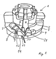
- a bearing plate 1 (FIG. 1) carries two electrical contact elements 2.
- the contact elements 2 provide the electrical connection between electrical Connections of the electrical device and contact brushes of the electric motor ago.
- This one has one Housing 3 (Fig. 3) made of sheet metal, on its inside the laminated cores of the stator receives. In the housing 3, both end shields by means of a federal 4 a Centering flange 5 pushed into and connected in a press fit with the housing 3.
- the contact element 2 is connected via a connecting wire 6, a capacitor 7 and a Lead 8 connected to the housing 3.
- the connecting wire 8 is located in one Bulge 9 of the centering 5 and protrudes between a lower edge 10 of the Centering flange 5 and an upper edge 11 of the housing 3 out, so that the end the lead wire 8 flush with the outer jacket wall of the housing 3 and the Centering flange 5 is removable.
- the collar 4 has two recesses 12, 13, by the connecting wire 8 to a projection 14 of the collar 4 on the inside pushed around.
- the housing 3 has in the region of its upper edge 11 projecting tongues 15, 16, 17th on, which is bent to fasten the bearing plate 1 to the housing 3 inwards become.
- the tongue 15 rests on a bottom 18 (FIG. 3) of the bulge 9 and clamps the connecting wire 8 against the ground 18.
- the connecting wire 6 is thereby firmly clamped against the bearing plate 1, that this is introduced into a V-shaped groove 19.
- a slot-shaped Recess 20 arranged substantially at a right angle to the direction the groove 19 extends.
- the recess 20 receives the contact element 2. This expresses when pushing into the recess 20, the connecting wire 6 down in the Well, so that it is clamped.
- the contact element 2 also has a V-shaped groove on its underside 21, so that the connection wire is clamped on both sides very precisely localized.
Landscapes
- Physics & Mathematics (AREA)
- Electromagnetism (AREA)
- Engineering & Computer Science (AREA)
- Power Engineering (AREA)
- Motor Or Generator Frames (AREA)
- Valve Device For Special Equipments (AREA)
- Transition And Organic Metals Composition Catalysts For Addition Polymerization (AREA)
- Glass Compositions (AREA)
- Dc Machiner (AREA)
Description
- Figur 1
- einen Lagerschild mit einem Kontaktelement in perspektivischer Ansicht,
- Figur 2
- den Lagerschild gemäß Figur 1 in Verbindung mit einem Motorgehäuse,
- Figur 3
- eine Draufsicht auf einen Zentrierflansch des Lagerschildes,
- Figur 4
- eine Schnittansicht entlang einer Linie A-A aus Figur 3 und
- Figur 5
- eine Schnittansicht entlang einer Linie B-B aus Figur 4.
Claims (5)
- Elektromotor mit einem hohlzylindrischen Motorgehäuse (3), in dem ein Rotor durch ein erstes und ein zweites, jeweils einen Zentrierflansch (5) aufweisendes Lagerschild (1) gelagert ist, sowie mit einem diskreten elektrischen Bauelement (7), das zu elektrischen Anschlüssen des Elektromotors parallel geschaltet ist, die von Kontaktelementen (2) gebildet werden, die auf dem ersten Lagerschild (1) angeordnet sind, wobei das Bauelement (7) über einen ersten Anschlussdraht (6) mit wenigstens einem der Kontaktelement (2) verbunden ist, dadurch gekennzeichnet, dass das Kontaktelement (2) in eine Vertiefung (20) einer sich im wesentlichen V-förmig in Einsetzrichtung verjüngenden Nut (19) hineingedrückt ist, in die der erste Anschlussdraht (6) eingelegt ist.
- Elektromotor nach Anspruch 1, dadurch gekennzeichnet, dass das Kontaktelement (2) auf seiner Unterseite eine zweite, im wesentlichen V-förmige Nut (21) aufweist, die sich entgegen der Einsetzrichtung verjüngt.
- Elektromotor nach Anspruch 1 oder 2, dadurch gekennzeichnet, dass das Kontaktelement (2) als flaches Plättchen ausgebildet ist und dass die Vertiefung (20) entsprechend dem Querschnitt des Kontaktelements (2) schlitzförmig ist.
- Elektromotor nach einem der Ansprüche 1 bis 3, dadurch gekennzeichnet, dass das Motorgehäuse (3) aus einem elektrisch leitfähigen Material besteht und dass ein zweiter Anschlussdraht (8) des Bauelements (7) zwischen dem Zentrierflansch (5) des ersten Lagerschildes (1) und dem Motorgehäuse (3) eingelegt ist.
- Elektromotor mit einem hohlzylindrischen Motorgehäuse (3), in dem ein Rotor durch ein erstes und ein zweites, jeweils einen Zentrierflansch (5) aufweisendes Lagerschild (1) gelagert ist, auf dem elektrische Anschlüsse (2) angeordnet sind, von denen einer mit dem Motorgehäuse (3) verbunden ist, das aus einem elektrisch leitfähigen Material besteht, wobei ein erster Anschlussdraht (6) eines diskreten elektrischen Bauelements (7) mit wenigstens einem Kontaktelement (2) verbunden ist und ein zweiter Anschlussdraht (8) des Bauelements (7) zwischen dem Zentrierflansch (5) des ersten Lagerschildes (1) und dem Motorgehäuse (3) eingelegt ist, wobei der Zentrierflansch (5) eine sich in radialer Richtung erstrekkende Ausbuchtung (9) aufweist, dadurch gekennzeichnet, dass auf dem Boden (18) der Ausbuchtung (9) das Ende des zweiten Anschlussdrahtes (8) aufgelegt ist, und dass das Motorgehäuse eine Zunge (16) aufweist, durch die das Ende des Anschlussdrahtes (8) auf dem Boden (18) der Ausbuchtung (9) eingeklemmt ist.
Priority Applications (1)
| Application Number | Priority Date | Filing Date | Title |
|---|---|---|---|
| SI200330193T SI1481462T1 (sl) | 2002-02-27 | 2003-02-19 | Elektromotor |
Applications Claiming Priority (3)
| Application Number | Priority Date | Filing Date | Title |
|---|---|---|---|
| DE10208367 | 2002-02-27 | ||
| DE10208367A DE10208367A1 (de) | 2002-02-27 | 2002-02-27 | Elektromotor |
| PCT/EP2003/001674 WO2003073588A2 (de) | 2002-02-27 | 2003-02-19 | Elektromotor |
Publications (2)
| Publication Number | Publication Date |
|---|---|
| EP1481462A2 EP1481462A2 (de) | 2004-12-01 |
| EP1481462B1 true EP1481462B1 (de) | 2005-12-14 |
Family
ID=27675029
Family Applications (1)
| Application Number | Title | Priority Date | Filing Date |
|---|---|---|---|
| EP03717190A Expired - Lifetime EP1481462B1 (de) | 2002-02-27 | 2003-02-19 | Elektromotor |
Country Status (12)
| Country | Link |
|---|---|
| US (1) | US7365459B2 (de) |
| EP (1) | EP1481462B1 (de) |
| AT (1) | ATE313163T1 (de) |
| AU (1) | AU2003221484A1 (de) |
| DE (2) | DE10208367A1 (de) |
| DK (1) | DK1481462T3 (de) |
| ES (1) | ES2254923T3 (de) |
| HR (1) | HRP20040770B1 (de) |
| PL (1) | PL200690B1 (de) |
| RS (1) | RS49914B (de) |
| RU (1) | RU2285996C2 (de) |
| WO (1) | WO2003073588A2 (de) |
Families Citing this family (7)
| Publication number | Priority date | Publication date | Assignee | Title |
|---|---|---|---|---|
| RU2330371C1 (ru) * | 2007-01-11 | 2008-07-27 | Открытое акционерное общество "АВТОВАЗ" | Тяговый мехатронный модуль |
| RU2345466C1 (ru) * | 2007-09-28 | 2009-01-27 | Государственное Научное Учреждение "Объединенный Институт Машиностроения Национальной Академии Наук Беларуси" | Электродвигатель |
| JP4861305B2 (ja) * | 2007-12-28 | 2012-01-25 | マブチモーター株式会社 | 有ブラシdcモータのケース蓋組立体 |
| CN101741181B (zh) * | 2008-11-26 | 2013-06-12 | 德昌电机(深圳)有限公司 | 用于暖通空调领域的电机 |
| JP5840903B2 (ja) * | 2011-09-16 | 2016-01-06 | アスモ株式会社 | モータ |
| JP5768642B2 (ja) * | 2011-10-04 | 2015-08-26 | 株式会社デンソー | スタータ |
| JP2013079599A (ja) * | 2011-10-04 | 2013-05-02 | Denso Corp | スタータ |
Family Cites Families (14)
| Publication number | Priority date | Publication date | Assignee | Title |
|---|---|---|---|---|
| GB1427417A (en) * | 1973-10-04 | 1976-03-10 | Westool Ltd | Electric motor |
| DE2810215C3 (de) * | 1978-03-09 | 1993-12-02 | Bosch Gmbh Robert | Verfahren zum Aufbringen eines zusätzlichen Rückschlusses auf das Gehäuse einer elektrischen Maschine |
| US4513214A (en) * | 1983-10-03 | 1985-04-23 | Allied Corporation | Dynamoelectric machine |
| US4673837A (en) * | 1984-05-11 | 1987-06-16 | Amp Incorporated | Motor brush assembly |
| JPS61144765U (de) * | 1985-02-25 | 1986-09-06 | ||
| US5015894A (en) * | 1990-02-13 | 1991-05-14 | Emerson Electric Co. | Unit bearing leadless motor |
| GB2248348B (en) * | 1990-09-28 | 1994-04-27 | Johnson Electric Sa | A brush holder for an electric motor |
| JP3102665B2 (ja) * | 1992-02-17 | 2000-10-23 | 三菱電機株式会社 | 電動機 |
| US6106324A (en) * | 1995-07-26 | 2000-08-22 | Dana Corporation | Programmable termination strip for electric motor |
| DE19810873B4 (de) * | 1997-04-30 | 2004-10-28 | Braun Gmbh | Elektromotor |
| DE19902433C1 (de) * | 1999-01-22 | 2000-09-28 | Buhler Motor Gmbh | Kommutatormotor |
| DE29924031U1 (de) * | 1999-05-27 | 2001-10-18 | J. Stehle + Söhne AG, 73773 Aichwald | Antriebsvorrichtung einer Jalousie, eines Rolladens o.dgl. |
| DE10014474A1 (de) * | 2000-03-23 | 2001-10-04 | Bosch Gmbh Robert | Zugentlastungsbauteil mit integriertem Kondensator |
| SI21004A (sl) * | 2001-07-23 | 2003-02-28 | Domel Elektromotorji In | Izobljšan ležajni ščit pri enosmernem kolektorskem motorju s trajnimi magneti |
-
2002
- 2002-02-27 DE DE10208367A patent/DE10208367A1/de not_active Withdrawn
-
2003
- 2003-02-19 EP EP03717190A patent/EP1481462B1/de not_active Expired - Lifetime
- 2003-02-19 RS YUP-719/04A patent/RS49914B/sr unknown
- 2003-02-19 ES ES03717190T patent/ES2254923T3/es not_active Expired - Lifetime
- 2003-02-19 AU AU2003221484A patent/AU2003221484A1/en not_active Abandoned
- 2003-02-19 RU RU2004124532/11A patent/RU2285996C2/ru not_active IP Right Cessation
- 2003-02-19 AT AT03717190T patent/ATE313163T1/de active
- 2003-02-19 WO PCT/EP2003/001674 patent/WO2003073588A2/de not_active Ceased
- 2003-02-19 PL PL371047A patent/PL200690B1/pl unknown
- 2003-02-19 DE DE50301923T patent/DE50301923D1/de not_active Expired - Lifetime
- 2003-02-19 HR HR20040770A patent/HRP20040770B1/xx not_active IP Right Cessation
- 2003-02-19 DK DK03717190T patent/DK1481462T3/da active
-
2004
- 2004-08-27 US US10/928,216 patent/US7365459B2/en not_active Expired - Fee Related
Also Published As
| Publication number | Publication date |
|---|---|
| ES2254923T3 (es) | 2006-06-16 |
| RU2004124532A (ru) | 2005-06-10 |
| PL371047A1 (en) | 2005-06-13 |
| US20050040717A1 (en) | 2005-02-24 |
| HRP20040770A2 (en) | 2004-12-31 |
| WO2003073588A2 (de) | 2003-09-04 |
| WO2003073588A3 (de) | 2004-02-05 |
| AU2003221484A1 (en) | 2003-09-09 |
| DK1481462T3 (da) | 2006-04-10 |
| EP1481462A2 (de) | 2004-12-01 |
| YU71904A (sh) | 2006-08-17 |
| RU2285996C2 (ru) | 2006-10-20 |
| PL200690B1 (pl) | 2009-01-30 |
| DE10208367A1 (de) | 2003-09-04 |
| DE50301923D1 (de) | 2006-01-19 |
| RS49914B (sr) | 2008-09-29 |
| ATE313163T1 (de) | 2005-12-15 |
| US7365459B2 (en) | 2008-04-29 |
| HRP20040770B1 (hr) | 2009-10-31 |
Similar Documents
| Publication | Publication Date | Title |
|---|---|---|
| DE202011100866U1 (de) | Bürstenanordnung und eine solche verwendender Elektromotor | |
| EP0088910B1 (de) | Drehstromgenerator mit Dreiphasengleichrichter für Fahrzeuge | |
| EP0727864B1 (de) | Verschaltungsanordnung für einen Elektromotor | |
| WO1995028029A1 (de) | Stromzuführungsanordnung für einen elektromotor mit vier bürsten | |
| DE3538940A1 (de) | Verdrahtungsanordnung fuer den motor eines elektrowerkzeugs | |
| EP1481462B1 (de) | Elektromotor | |
| DE69600844T2 (de) | Elektromotor-zusammenbau und elektrokontakt zur verwendung dafuer | |
| DE4114738A1 (de) | Elektromotor sowie verfahren zur herstellung eines solchen | |
| DE102020210692A1 (de) | Elektrische Maschine mit einer elektrisch leitenden Abschirmplatte | |
| EP1865589B1 (de) | Statoreinheit für einen Elektromotor | |
| EP1668747B1 (de) | Kommutator für eine elektrische maschine | |
| EP0504469A1 (de) | Elektrische Kontaktverbindung | |
| DE102010041037A1 (de) | Schneidklemme zur Herstellung einer elektrischen Verbindung sowie Kontaktierungsanordnung mit einer derartigen Schneidklemme | |
| DE3871606T2 (de) | Isolierende endscheibe fuer einen laeufer einer elektrischen drehmaschine. | |
| EP0960462B1 (de) | Bürstenhalteanordnung | |
| DE202020005555U1 (de) | Elektrische Maschine mit einer elektrisch leitenden Abschirmplatte | |
| DE29619139U1 (de) | Anschlußstück für Cageclamp-Anschlußtechnik | |
| DE3314412C3 (de) | Kleine Kollektormaschine, insbesondere Motor | |
| EP1206005A1 (de) | Crimpkontakt für Leiterplatten | |
| EP4354663B1 (de) | Quetschverbinder zu einem mechanischen und elektrisch leitenden verbinden eines elektrischen anschlusskontakts mit einem elektrischen leiter und quetschverbindung eines elektrischen anschlusskontakts mit einem elektrischen leiter | |
| DE3538941A1 (de) | Feldstecker fuer einen elektromotor | |
| EP1285485B1 (de) | Elektromotor, insbesondere kommutatormotor | |
| DE19523899B4 (de) | Mechanisch kommutierter Elektromotor | |
| WO2003100920A1 (de) | Bürste oder kohlebürste für einen elektromotor sowie elektromotor mit einer solchen bürste | |
| DE4440942A1 (de) | Elektrische Anschlußvorrichtung, Bürstenhalter für eine rotierende elektrische Maschine in der Ausführung mit einer solchen Anschlußvorrichtung und Wechselstromgenerator für Kraftfahrzeuge, der mit einem solchen Bürstenhalter ausgerüstet ist |
Legal Events
| Date | Code | Title | Description |
|---|---|---|---|
| PUAI | Public reference made under article 153(3) epc to a published international application that has entered the european phase |
Free format text: ORIGINAL CODE: 0009012 |
|
| 17P | Request for examination filed |
Effective date: 20040927 |
|
| AK | Designated contracting states |
Kind code of ref document: A2 Designated state(s): AT BE BG CH CY CZ DE DK EE ES FI FR GB GR HU IE IT LI LU MC NL PT SE SI SK TR |
|
| AX | Request for extension of the european patent |
Extension state: AL LT LV MK RO |
|
| GRAP | Despatch of communication of intention to grant a patent |
Free format text: ORIGINAL CODE: EPIDOSNIGR1 |
|
| GRAS | Grant fee paid |
Free format text: ORIGINAL CODE: EPIDOSNIGR3 |
|
| GRAA | (expected) grant |
Free format text: ORIGINAL CODE: 0009210 |
|
| AK | Designated contracting states |
Kind code of ref document: B1 Designated state(s): AT BE BG CH CY CZ DE DK EE ES FI FR GB GR HU IE IT LI LU MC NL PT SE SI SK TR |
|
| PG25 | Lapsed in a contracting state [announced via postgrant information from national office to epo] |
Ref country code: IE Free format text: LAPSE BECAUSE OF FAILURE TO SUBMIT A TRANSLATION OF THE DESCRIPTION OR TO PAY THE FEE WITHIN THE PRESCRIBED TIME-LIMIT Effective date: 20051214 Ref country code: IT Free format text: LAPSE BECAUSE OF FAILURE TO SUBMIT A TRANSLATION OF THE DESCRIPTION OR TO PAY THE FEE WITHIN THE PRESCRIBED TIME-LIMIT;WARNING: LAPSES OF ITALIAN PATENTS WITH EFFECTIVE DATE BEFORE 2007 MAY HAVE OCCURRED AT ANY TIME BEFORE 2007. THE CORRECT EFFECTIVE DATE MAY BE DIFFERENT FROM THE ONE RECORDED. Effective date: 20051214 Ref country code: NL Free format text: LAPSE BECAUSE OF FAILURE TO SUBMIT A TRANSLATION OF THE DESCRIPTION OR TO PAY THE FEE WITHIN THE PRESCRIBED TIME-LIMIT Effective date: 20051214 Ref country code: FI Free format text: LAPSE BECAUSE OF FAILURE TO SUBMIT A TRANSLATION OF THE DESCRIPTION OR TO PAY THE FEE WITHIN THE PRESCRIBED TIME-LIMIT Effective date: 20051214 |
|
| REG | Reference to a national code |
Ref country code: GB Ref legal event code: FG4D Free format text: NOT ENGLISH |
|
| REG | Reference to a national code |
Ref country code: CH Ref legal event code: EP |
|
| REG | Reference to a national code |
Ref country code: IE Ref legal event code: FG4D Free format text: LANGUAGE OF EP DOCUMENT: GERMAN |
|
| REF | Corresponds to: |
Ref document number: 50301923 Country of ref document: DE Date of ref document: 20060119 Kind code of ref document: P |
|
| GBT | Gb: translation of ep patent filed (gb section 77(6)(a)/1977) |
Effective date: 20060119 |
|
| PG25 | Lapsed in a contracting state [announced via postgrant information from national office to epo] |
Ref country code: LU Free format text: LAPSE BECAUSE OF NON-PAYMENT OF DUE FEES Effective date: 20060228 Ref country code: MC Free format text: LAPSE BECAUSE OF NON-PAYMENT OF DUE FEES Effective date: 20060228 Ref country code: BE Free format text: LAPSE BECAUSE OF NON-PAYMENT OF DUE FEES Effective date: 20060228 |
|
| PG25 | Lapsed in a contracting state [announced via postgrant information from national office to epo] |
Ref country code: BG Free format text: LAPSE BECAUSE OF FAILURE TO SUBMIT A TRANSLATION OF THE DESCRIPTION OR TO PAY THE FEE WITHIN THE PRESCRIBED TIME-LIMIT Effective date: 20060314 Ref country code: GR Free format text: LAPSE BECAUSE OF FAILURE TO SUBMIT A TRANSLATION OF THE DESCRIPTION OR TO PAY THE FEE WITHIN THE PRESCRIBED TIME-LIMIT Effective date: 20060314 |
|
| REG | Reference to a national code |
Ref country code: SE Ref legal event code: TRGR |
|
| REG | Reference to a national code |
Ref country code: DK Ref legal event code: T3 |
|
| PG25 | Lapsed in a contracting state [announced via postgrant information from national office to epo] |
Ref country code: PT Free format text: LAPSE BECAUSE OF FAILURE TO SUBMIT A TRANSLATION OF THE DESCRIPTION OR TO PAY THE FEE WITHIN THE PRESCRIBED TIME-LIMIT Effective date: 20060515 |
|
| NLV1 | Nl: lapsed or annulled due to failure to fulfill the requirements of art. 29p and 29m of the patents act | ||
| PG25 | Lapsed in a contracting state [announced via postgrant information from national office to epo] |
Ref country code: HU Free format text: LAPSE BECAUSE OF FAILURE TO SUBMIT A TRANSLATION OF THE DESCRIPTION OR TO PAY THE FEE WITHIN THE PRESCRIBED TIME-LIMIT Effective date: 20060615 |
|
| REG | Reference to a national code |
Ref country code: ES Ref legal event code: FG2A Ref document number: 2254923 Country of ref document: ES Kind code of ref document: T3 |
|
| ET | Fr: translation filed | ||
| REG | Reference to a national code |
Ref country code: IE Ref legal event code: FD4D |
|
| PLBE | No opposition filed within time limit |
Free format text: ORIGINAL CODE: 0009261 |
|
| STAA | Information on the status of an ep patent application or granted ep patent |
Free format text: STATUS: NO OPPOSITION FILED WITHIN TIME LIMIT |
|
| 26N | No opposition filed |
Effective date: 20060915 |
|
| PG25 | Lapsed in a contracting state [announced via postgrant information from national office to epo] |
Ref country code: CH Free format text: LAPSE BECAUSE OF NON-PAYMENT OF DUE FEES Effective date: 20070228 Ref country code: LI Free format text: LAPSE BECAUSE OF NON-PAYMENT OF DUE FEES Effective date: 20070228 |
|
| REG | Reference to a national code |
Ref country code: CH Ref legal event code: PL |
|
| BERE | Be: lapsed |
Owner name: BSH BOSCH UND SIEMENS HAUSGERATE G.M.B.H. Effective date: 20060228 |
|
| PG25 | Lapsed in a contracting state [announced via postgrant information from national office to epo] |
Ref country code: EE Free format text: LAPSE BECAUSE OF FAILURE TO SUBMIT A TRANSLATION OF THE DESCRIPTION OR TO PAY THE FEE WITHIN THE PRESCRIBED TIME-LIMIT Effective date: 20051214 |
|
| PG25 | Lapsed in a contracting state [announced via postgrant information from national office to epo] |
Ref country code: TR Free format text: LAPSE BECAUSE OF FAILURE TO SUBMIT A TRANSLATION OF THE DESCRIPTION OR TO PAY THE FEE WITHIN THE PRESCRIBED TIME-LIMIT Effective date: 20051214 |
|
| PG25 | Lapsed in a contracting state [announced via postgrant information from national office to epo] |
Ref country code: CY Free format text: LAPSE BECAUSE OF FAILURE TO SUBMIT A TRANSLATION OF THE DESCRIPTION OR TO PAY THE FEE WITHIN THE PRESCRIBED TIME-LIMIT Effective date: 20051214 |
|
| PGFP | Annual fee paid to national office [announced via postgrant information from national office to epo] |
Ref country code: CZ Payment date: 20110209 Year of fee payment: 9 Ref country code: SK Payment date: 20110215 Year of fee payment: 9 |
|
| PGFP | Annual fee paid to national office [announced via postgrant information from national office to epo] |
Ref country code: SE Payment date: 20120221 Year of fee payment: 10 Ref country code: DK Payment date: 20120216 Year of fee payment: 10 |
|
| REG | Reference to a national code |
Ref country code: DK Ref legal event code: EBP |
|
| REG | Reference to a national code |
Ref country code: SE Ref legal event code: EUG |
|
| PG25 | Lapsed in a contracting state [announced via postgrant information from national office to epo] |
Ref country code: CZ Free format text: LAPSE BECAUSE OF NON-PAYMENT OF DUE FEES Effective date: 20130219 Ref country code: SE Free format text: LAPSE BECAUSE OF NON-PAYMENT OF DUE FEES Effective date: 20130220 Ref country code: SK Free format text: LAPSE BECAUSE OF NON-PAYMENT OF DUE FEES Effective date: 20130219 |
|
| REG | Reference to a national code |
Ref country code: SK Ref legal event code: MM4A Ref document number: E 428 Country of ref document: SK Effective date: 20130219 |
|
| PG25 | Lapsed in a contracting state [announced via postgrant information from national office to epo] |
Ref country code: DK Free format text: LAPSE BECAUSE OF NON-PAYMENT OF DUE FEES Effective date: 20130228 |
|
| REG | Reference to a national code |
Ref country code: FR Ref legal event code: PLFP Year of fee payment: 13 |
|
| REG | Reference to a national code |
Ref country code: DE Ref legal event code: R081 Ref document number: 50301923 Country of ref document: DE Owner name: BSH HAUSGERAETE GMBH, DE Free format text: FORMER OWNER: BSH BOSCH UND SIEMENS HAUSGERAETE GMBH, 81739 MUENCHEN, DE Effective date: 20150407 |
|
| REG | Reference to a national code |
Ref country code: ES Ref legal event code: PC2A Owner name: BSH HAUSGERATE GMBH Effective date: 20150527 |
|
| REG | Reference to a national code |
Ref country code: SI Ref legal event code: SP73 Owner name: BSH HAUSGERAETE GMBH; DE Effective date: 20150529 |
|
| REG | Reference to a national code |
Ref country code: AT Ref legal event code: HC Ref document number: 313163 Country of ref document: AT Kind code of ref document: T Owner name: BSH HAUSGERAETE GMBH, DE Effective date: 20150528 |
|
| REG | Reference to a national code |
Ref country code: FR Ref legal event code: CD Owner name: BSH HAUSGERATE GMBH Effective date: 20151022 |
|
| REG | Reference to a national code |
Ref country code: FR Ref legal event code: PLFP Year of fee payment: 14 |
|
| REG | Reference to a national code |
Ref country code: FR Ref legal event code: PLFP Year of fee payment: 15 |
|
| REG | Reference to a national code |
Ref country code: FR Ref legal event code: PLFP Year of fee payment: 16 |
|
| PGFP | Annual fee paid to national office [announced via postgrant information from national office to epo] |
Ref country code: ES Payment date: 20180322 Year of fee payment: 16 |
|
| PGFP | Annual fee paid to national office [announced via postgrant information from national office to epo] |
Ref country code: AT Payment date: 20180220 Year of fee payment: 16 Ref country code: SI Payment date: 20180209 Year of fee payment: 16 |
|
| REG | Reference to a national code |
Ref country code: AT Ref legal event code: MM01 Ref document number: 313163 Country of ref document: AT Kind code of ref document: T Effective date: 20190219 |
|
| PG25 | Lapsed in a contracting state [announced via postgrant information from national office to epo] |
Ref country code: SI Free format text: LAPSE BECAUSE OF NON-PAYMENT OF DUE FEES Effective date: 20190220 |
|
| REG | Reference to a national code |
Ref country code: SI Ref legal event code: KO00 Effective date: 20191007 |
|
| PG25 | Lapsed in a contracting state [announced via postgrant information from national office to epo] |
Ref country code: AT Free format text: LAPSE BECAUSE OF NON-PAYMENT OF DUE FEES Effective date: 20190219 |
|
| REG | Reference to a national code |
Ref country code: ES Ref legal event code: FD2A Effective date: 20200330 |
|
| PG25 | Lapsed in a contracting state [announced via postgrant information from national office to epo] |
Ref country code: ES Free format text: LAPSE BECAUSE OF NON-PAYMENT OF DUE FEES Effective date: 20190220 |
|
| PGFP | Annual fee paid to national office [announced via postgrant information from national office to epo] |
Ref country code: GB Payment date: 20220221 Year of fee payment: 20 Ref country code: DE Payment date: 20220228 Year of fee payment: 20 |
|
| PGFP | Annual fee paid to national office [announced via postgrant information from national office to epo] |
Ref country code: FR Payment date: 20220221 Year of fee payment: 20 |
|
| REG | Reference to a national code |
Ref country code: DE Ref legal event code: R071 Ref document number: 50301923 Country of ref document: DE |
|
| REG | Reference to a national code |
Ref country code: GB Ref legal event code: PE20 Expiry date: 20230218 |
|
| PG25 | Lapsed in a contracting state [announced via postgrant information from national office to epo] |
Ref country code: GB Free format text: LAPSE BECAUSE OF EXPIRATION OF PROTECTION Effective date: 20230218 |