EP1482467A1 - Capteur d'alarme au déclenchement manuel - Google Patents
Capteur d'alarme au déclenchement manuel Download PDFInfo
- Publication number
- EP1482467A1 EP1482467A1 EP03011997A EP03011997A EP1482467A1 EP 1482467 A1 EP1482467 A1 EP 1482467A1 EP 03011997 A EP03011997 A EP 03011997A EP 03011997 A EP03011997 A EP 03011997A EP 1482467 A1 EP1482467 A1 EP 1482467A1
- Authority
- EP
- European Patent Office
- Prior art keywords
- alarm button
- shift gate
- guide
- button
- detector according
- Prior art date
- Legal status (The legal status is an assumption and is not a legal conclusion. Google has not performed a legal analysis and makes no representation as to the accuracy of the status listed.)
- Granted
Links
Images


Classifications
-
- G—PHYSICS
- G08—SIGNALLING
- G08B—SIGNALLING SYSTEMS, e.g. PERSONAL CALLING SYSTEMS; ORDER TELEGRAPHS; ALARM SYSTEMS
- G08B25/00—Alarm systems in which the location of the alarm condition is signalled to a central station, e.g. fire or police telegraphic systems
- G08B25/12—Manually actuated calamity alarm transmitting arrangements emergency non-personal manually actuated alarm, activators, e.g. details of alarm push buttons mounted on an infrastructure
Definitions
- the present invention relates to a hand hazard detector with detector housing, front panel, fragile element and a switch insert with a limit switch, a switching element and an alarm button.
- Such Hand carmelder especially in security systems for fire or police emergency call are usually used in two versions, for direct and indirect actuation, manufactured.
- the type of detector for indirect actuation is a so-called Alarm button execution.
- a glass pane the fragile element
- the trigger element is thus the alarm button.
- the Glass pane are hit, whereupon the alarm button springs out by spring pressure. So here is the trigger element formed by the disc and the alarm button.
- the Alarm message as electrical signal to an alarm center forwards. That's it extremely important that the hand hazard detectors work flawlessly and at any time are ready for a safe alarm delivery.
- the object of the invention is to develop the described hand hazard detector in such a way that the switch insert regardless of mechanical forces and manufacturing tolerances a Reliable alarm delivery ensures and optionally for the two detector variants can be used.
- the switching insert with regard to a cost-effective Be optimized production.
- This object is achieved in that the switching element by a with the alarm button connected and provided for operating the limit switch gate is formed, which is guided in a provided on the front panel guide.
- tilting the alarm button can secure Operation of the limit switch no longer adversely affect the requirements the accuracy of the leadership can be significantly reduced.
- a first preferred embodiment of the hand hazard detector according to the invention is characterized in that the shift gate worked on the alarm button and at their Longitudinal edges of a rail-like guide is included.
- a second preferred embodiment of the hand hazard detector according to the invention is characterized in that the shift gate a button in the form of a wedge or Has double wedge, which rests on her foot at the limit switch and this at Shifting the shift gate and thus the alarm button operated.
- a third preferred embodiment of the hand hazard detector according to the invention is characterized by a alarm button on the opposite of the shift gate Side attached guide bar, which provided in one on the front panel Guide rail is guided.
- the rail-like guide for the shift gate and the guide rail for the guide bar a common guide part, in which the alarm button, shift gate and guide web formed part is twisting and tilting out.
- a further preferred embodiment of the inventive hand hazard detector in which the alarm button is designed as a push button, is characterized in that the Wegkulisse has a flush with the button locking projection, and that a is provided in the operating state of the detector on the shift gate fitting locking lever.
- the basic structure of a hand hazard detector consists of a housing that after Front is covered by a front panel, arranged in front of the front panel fragile element, such as a glass pane, one guided in the front panel Alarm button and behind the front panel in the detector inside arranged switching insert.
- This structure is assumed to be known and is not described here in detail; it will be in In this connection reference is made to EP-A-0 592 925 and EP-A-1 288 881.
- FIGs 1 and 2 are only the essential parts for understanding the invention of the hand hazard detector according to the invention, namely the one designated by the reference numeral 1 Front plate, designated by the reference numeral 2 alarm button and the switch insert (without Printed circuit board).
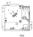
- Fig. 3 shows the front panel with a screwed circuit board.
- the front panel 1 is shown in the form of a trough and contains in the center a recess for the alarm button 2, which is pressed by a central spring 3 to the outside becomes.
- the switch insert containing part of the front panel 1 is to the rear through a printed circuit board 4 (Fig. 3) covered.
- the circuit board 4 is screwed to the front panel 1 and forms a stop for the spring 3. All current-carrying parts are on the circuit board. 4 placed, resulting in a cost savings.
- the switch insert contains substantially a arranged on the circuit board limit switch 5 and one to the alarm button. 2 engaged shift gate 6.
- the shift gate 6 has the shape of a small plate, which with the alarm button 2 is connected via a narrow web. At the of the alarm button facing away from a wedge-shaped rising button 7 is arranged at the limit switch 5 is applied and this pressed when pressing the alarm button 2.
- a sawtooth-like locking projection 8 is provided at a distance from the button 7, at a distance from the button 7, a sawtooth-like locking projection 8 is provided.
- a locking tab 9 of a locking lever 10 in space between the button 7 and the locking projection 8 on the shift gate 6 at.
- the locking projection 8 slides under the locking tab 9, whereby the locking lever 10 is swung short and after the locking projection. 8 springs back and thus locks the alarm button 2 in its depressed alarm position.
- the locking lever 10 is formed with two arms and in its center at a fixed Bearing bush 11 is pivotally mounted on the front panel 1.
- the shorter arm of the locking lever 10 carries the locking lug 9 and the longer arm serves as an actuating arm and protrudes its free end 12 laterally out of the detector.
- the actuating arm is an elastic Organ 13 associated in the manner of a leaf spring, which on the adjacent side wall of the Front plate 1 rests and the locking tab 9 presses against the shift gate 6.
- a T-shaped Guided guide web 18 On the shift gate 6 radially opposite side of the alarm button 2 is a T-shaped Guided guide web 18, which together with the alarm button 2 and the shift gate. 6 forms a common, one-piece actuating and switching member. This organ is in one guided on the inside of the front panel 1 arranged common guide member 14.
- the guide member 14 consists of the guide rail 16 for the shift gate 6, the guide rail 17 for the guide web 18 and a cylindrical central portion 15, which serves as a guide for the alarm button 2 is used.
- the length of each of these guides is greater than the length of the too leading part and is dimensioned so that the alarm button 2, the gate 6 and the Guide web 13 even when pushing the alarm button 2 in its entire length in the respective leadership are guided. Due to the fact that the shift gate 6 in the guide rail 16 is guided, the shift gate 6 moves along a well-defined path, so that the Limit switch 5 is operated under all circumstances with certainty. The exact movement plane the shift gate 6 also allows the use of a limit switch 5 with relative large switching stroke.
- the guide web 18 and the guide rail 17 provide an additional Safety for the exact guidance and against every tilting and / or jamming of the Alarm button 2.
- the guide rail 16 pierces its free end of the circuit board 4 and is in a corresponding opening of the circuit board fixed.
- hand hazard detectors are in alarm button and jumping button design known.
- the detector shown is an alarm button version for indirect Activity.
- For the triggering of an alarm is first the projecting from the windscreen 1 Press the alarm button 2 covering glass pane and then press the alarm button 2.
- the alarm button 2 is actuated via the shift gate 6, the limit switch 5 and is determined by the Locking lever 10 fixed in this position.
- To release the alarm button 2 the free end 12th of the locking lever 10 are pivoted in the direction of arrow A, whereby the locking nose 9, the shift gate 6 is free and the spring 3 the alarm button 2 back to its operating position suppressed.
- the Hand biomelder shown is with minor modifications as a detector in Spring button version can be used for direct operation.
- the locking lever 10 is removed and the alarm button 2 replaced by a button suitable for direct operation, itself from the alarm button 2 for indirect actuation essentially by a different shape the button 7 differs at the shift gate 6, because now the limit switch not when pushing in but when jumping out of the alarm button is pressed.
Landscapes
- Business, Economics & Management (AREA)
- Emergency Management (AREA)
- Physics & Mathematics (AREA)
- General Physics & Mathematics (AREA)
- Emergency Alarm Devices (AREA)
- Push-Button Switches (AREA)
- Rotary Switch, Piano Key Switch, And Lever Switch (AREA)
- Laser Surgery Devices (AREA)
- Saccharide Compounds (AREA)
- Control And Other Processes For Unpacking Of Materials (AREA)
- Alarm Systems (AREA)
- Gyroscopes (AREA)
- Measuring Pulse, Heart Rate, Blood Pressure Or Blood Flow (AREA)
- Rehabilitation Tools (AREA)
Priority Applications (10)
| Application Number | Priority Date | Filing Date | Title |
|---|---|---|---|
| ES03011997T ES2283679T3 (es) | 2003-05-28 | 2003-05-28 | Dispositivo de aviso de peligro manual. |
| EP03011997A EP1482467B1 (fr) | 2003-05-28 | 2003-05-28 | Capteur d'alarme au déclenchement manuel |
| DE50306849T DE50306849D1 (de) | 2003-05-28 | 2003-05-28 | Handgefahrenmelder |
| AT03011997T ATE357716T1 (de) | 2003-05-28 | 2003-05-28 | Handgefahrenmelder |
| AU2004202084A AU2004202084B2 (en) | 2003-05-28 | 2004-05-17 | Manually Operated Hazard-warning Alarm |
| PL04368066A PL368066A1 (en) | 2003-05-28 | 2004-05-18 | Manually operated alarm device |
| NO20042163A NO20042163L (no) | 2003-05-28 | 2004-05-25 | Hand-nodmelder |
| KR1020040037885A KR101054211B1 (ko) | 2003-05-28 | 2004-05-27 | 수동식 위험-경고 경보기 |
| CNB2004100457795A CN100430968C (zh) | 2003-05-28 | 2004-05-28 | 手动式危险警报器 |
| HK05106522.9A HK1073910B (en) | 2003-05-28 | 2005-07-29 | Manually operated hazard-warning alarm |
Applications Claiming Priority (1)
| Application Number | Priority Date | Filing Date | Title |
|---|---|---|---|
| EP03011997A EP1482467B1 (fr) | 2003-05-28 | 2003-05-28 | Capteur d'alarme au déclenchement manuel |
Publications (2)
| Publication Number | Publication Date |
|---|---|
| EP1482467A1 true EP1482467A1 (fr) | 2004-12-01 |
| EP1482467B1 EP1482467B1 (fr) | 2007-03-21 |
Family
ID=33104091
Family Applications (1)
| Application Number | Title | Priority Date | Filing Date |
|---|---|---|---|
| EP03011997A Expired - Lifetime EP1482467B1 (fr) | 2003-05-28 | 2003-05-28 | Capteur d'alarme au déclenchement manuel |
Country Status (9)
| Country | Link |
|---|---|
| EP (1) | EP1482467B1 (fr) |
| KR (1) | KR101054211B1 (fr) |
| CN (1) | CN100430968C (fr) |
| AT (1) | ATE357716T1 (fr) |
| AU (1) | AU2004202084B2 (fr) |
| DE (1) | DE50306849D1 (fr) |
| ES (1) | ES2283679T3 (fr) |
| NO (1) | NO20042163L (fr) |
| PL (1) | PL368066A1 (fr) |
Families Citing this family (1)
| Publication number | Priority date | Publication date | Assignee | Title |
|---|---|---|---|---|
| DE102007020283A1 (de) * | 2007-04-30 | 2008-11-13 | Robert Bosch Gmbh | Meldevorrichtung mit manueller Auslösung |
Citations (2)
| Publication number | Priority date | Publication date | Assignee | Title |
|---|---|---|---|---|
| DE3908885C1 (en) * | 1989-03-17 | 1990-05-03 | Siemens Ag, 1000 Berlin Und 8000 Muenchen, De | Alarm transmitter |
| DE4406428A1 (de) * | 1994-02-28 | 1995-08-31 | Merk Gmbh Telefonbau Fried | Gefahrenmelder |
Family Cites Families (5)
| Publication number | Priority date | Publication date | Assignee | Title |
|---|---|---|---|---|
| US4154189A (en) * | 1978-01-13 | 1979-05-15 | Ato, Inc. | Manual release and test apparatus for alarm system |
| US4551707A (en) * | 1982-05-27 | 1985-11-05 | Emhart Industries, Inc. | Fire alarm pull station |
| JPS6087093U (ja) | 1983-11-22 | 1985-06-15 | 奥野電器産業株式会社 | 火災報知機 |
| ATE162651T1 (de) * | 1992-10-13 | 1998-02-15 | Siemens Ag | Handgefahrenmelder |
| EP1288881B1 (fr) * | 2001-09-03 | 2005-05-18 | Siemens Building Technologies AG | Avertisseur manuel de risques |
-
2003
- 2003-05-28 ES ES03011997T patent/ES2283679T3/es not_active Expired - Lifetime
- 2003-05-28 AT AT03011997T patent/ATE357716T1/de not_active IP Right Cessation
- 2003-05-28 EP EP03011997A patent/EP1482467B1/fr not_active Expired - Lifetime
- 2003-05-28 DE DE50306849T patent/DE50306849D1/de not_active Expired - Lifetime
-
2004
- 2004-05-17 AU AU2004202084A patent/AU2004202084B2/en not_active Ceased
- 2004-05-18 PL PL04368066A patent/PL368066A1/xx unknown
- 2004-05-25 NO NO20042163A patent/NO20042163L/no not_active Application Discontinuation
- 2004-05-27 KR KR1020040037885A patent/KR101054211B1/ko not_active Expired - Fee Related
- 2004-05-28 CN CNB2004100457795A patent/CN100430968C/zh not_active Expired - Fee Related
Patent Citations (2)
| Publication number | Priority date | Publication date | Assignee | Title |
|---|---|---|---|---|
| DE3908885C1 (en) * | 1989-03-17 | 1990-05-03 | Siemens Ag, 1000 Berlin Und 8000 Muenchen, De | Alarm transmitter |
| DE4406428A1 (de) * | 1994-02-28 | 1995-08-31 | Merk Gmbh Telefonbau Fried | Gefahrenmelder |
Also Published As
| Publication number | Publication date |
|---|---|
| DE50306849D1 (de) | 2007-05-03 |
| PL368066A1 (en) | 2004-11-29 |
| ATE357716T1 (de) | 2007-04-15 |
| KR101054211B1 (ko) | 2011-08-03 |
| AU2004202084A1 (en) | 2004-12-16 |
| AU2004202084B2 (en) | 2008-09-04 |
| HK1073910A1 (zh) | 2005-10-21 |
| KR20040103371A (ko) | 2004-12-08 |
| NO20042163L (no) | 2004-11-26 |
| EP1482467B1 (fr) | 2007-03-21 |
| CN100430968C (zh) | 2008-11-05 |
| ES2283679T3 (es) | 2007-11-01 |
| CN1573832A (zh) | 2005-02-02 |
Similar Documents
| Publication | Publication Date | Title |
|---|---|---|
| DE3100862C2 (de) | Sicherheitsschalter | |
| AT412411B (de) | Elektromechanische feststellvorrichtung für türflügel mit einem türschliesser | |
| DE3302631C2 (de) | Sicherheitsschalter mit Fehlschließsicherung | |
| EP0892420A2 (fr) | Discontacteur à maximum avec cliquet pour la protection des moteurs | |
| EP0592925B1 (fr) | Avertisseur manuel de risques | |
| EP2633537A1 (fr) | Serrure à carte | |
| DE10013160B4 (de) | Schaltwelleneinheit für einen Schalter | |
| EP1288881B1 (fr) | Avertisseur manuel de risques | |
| DE2935420C2 (de) | Elektrische Ausschaltvorrichtung, insbesondere Seilzugnotschaltvorrichtung | |
| DE2833938B2 (de) | Schlüsselbetätigte Schalterschloßeinheit | |
| EP1482467B1 (fr) | Capteur d'alarme au déclenchement manuel | |
| DE3119165C2 (de) | Selbstschalter als Baueinheit aus einem Leitungsschutzschalter sowie Hilfs- und Signalschaltern | |
| EP0193017B1 (fr) | Dispositif d'actionnement du verrou de déclenchement | |
| EP0078953A1 (fr) | Bouton poussoir pour interrupteur électrique | |
| EP1245033B1 (fr) | Commutateur pour ouvre-porte | |
| EP1339932A2 (fr) | Dispositif pour actionner une serrure sur une porte, un cache-serrure ou analogue, notamment d'un vehicule | |
| DE102004018269B3 (de) | Manueller Gefahrenmelder | |
| EP2093735A1 (fr) | Commutateur d'urgence doté d'un élément de commutation bistable | |
| DE2551858C2 (de) | Endschalter | |
| EP1580363B1 (fr) | Dispositif pour protection ou surveillance des issues de secours ou similaire | |
| DE2455031C2 (de) | Sicherheitsschalter | |
| DE4406428C2 (de) | Gefahrenmelder | |
| EP0338969B1 (fr) | Armoire de commutation avec un appareil interrupteur de basse tension | |
| EP2437364A2 (fr) | Insert de profil de cadre, installation de battant en étant équipée et procédé de montage correspondant | |
| DE2501828C3 (de) | Adapter zur Auslösung eines Elektronenblitzes |
Legal Events
| Date | Code | Title | Description |
|---|---|---|---|
| PUAI | Public reference made under article 153(3) epc to a published international application that has entered the european phase |
Free format text: ORIGINAL CODE: 0009012 |
|
| AK | Designated contracting states |
Kind code of ref document: A1 Designated state(s): AT BE BG CH CY CZ DE DK EE ES FI FR GB GR HU IE IT LI LU MC NL PT RO SE SI SK TR |
|
| AX | Request for extension of the european patent |
Extension state: AL LT LV MK |
|
| 17P | Request for examination filed |
Effective date: 20050629 |
|
| RBV | Designated contracting states (corrected) |
Designated state(s): AT BE BG CH CY CZ DE DK EE ES FI FR GB GR HU IE IT LI LU MC NL PT RO SE SI SK TR |
|
| REG | Reference to a national code |
Ref country code: DE Ref legal event code: 8566 |
|
| RAP1 | Party data changed (applicant data changed or rights of an application transferred) |
Owner name: SIEMENS SCHWEIZ AG |
|
| GRAP | Despatch of communication of intention to grant a patent |
Free format text: ORIGINAL CODE: EPIDOSNIGR1 |
|
| GRAS | Grant fee paid |
Free format text: ORIGINAL CODE: EPIDOSNIGR3 |
|
| GRAA | (expected) grant |
Free format text: ORIGINAL CODE: 0009210 |
|
| AK | Designated contracting states |
Kind code of ref document: B1 Designated state(s): AT BE BG CH CY CZ DE DK EE ES FI FR GB GR HU IE IT LI LU MC NL PT RO SE SI SK TR |
|
| PG25 | Lapsed in a contracting state [announced via postgrant information from national office to epo] |
Ref country code: IE Free format text: LAPSE BECAUSE OF FAILURE TO SUBMIT A TRANSLATION OF THE DESCRIPTION OR TO PAY THE FEE WITHIN THE PRESCRIBED TIME-LIMIT Effective date: 20070321 Ref country code: SI Free format text: LAPSE BECAUSE OF FAILURE TO SUBMIT A TRANSLATION OF THE DESCRIPTION OR TO PAY THE FEE WITHIN THE PRESCRIBED TIME-LIMIT Effective date: 20070321 Ref country code: NL Free format text: LAPSE BECAUSE OF FAILURE TO SUBMIT A TRANSLATION OF THE DESCRIPTION OR TO PAY THE FEE WITHIN THE PRESCRIBED TIME-LIMIT Effective date: 20070321 Ref country code: FI Free format text: LAPSE BECAUSE OF FAILURE TO SUBMIT A TRANSLATION OF THE DESCRIPTION OR TO PAY THE FEE WITHIN THE PRESCRIBED TIME-LIMIT Effective date: 20070321 |
|
| REG | Reference to a national code |
Ref country code: GB Ref legal event code: FG4D Free format text: NOT ENGLISH |
|
| REG | Reference to a national code |
Ref country code: CH Ref legal event code: EP |
|
| REF | Corresponds to: |
Ref document number: 50306849 Country of ref document: DE Date of ref document: 20070503 Kind code of ref document: P |
|
| REG | Reference to a national code |
Ref country code: IE Ref legal event code: FG4D Free format text: LANGUAGE OF EP DOCUMENT: GERMAN |
|
| GBT | Gb: translation of ep patent filed (gb section 77(6)(a)/1977) |
Effective date: 20070530 |
|
| PG25 | Lapsed in a contracting state [announced via postgrant information from national office to epo] |
Ref country code: SE Free format text: LAPSE BECAUSE OF FAILURE TO SUBMIT A TRANSLATION OF THE DESCRIPTION OR TO PAY THE FEE WITHIN THE PRESCRIBED TIME-LIMIT Effective date: 20070621 |
|
| PG25 | Lapsed in a contracting state [announced via postgrant information from national office to epo] |
Ref country code: PT Free format text: LAPSE BECAUSE OF FAILURE TO SUBMIT A TRANSLATION OF THE DESCRIPTION OR TO PAY THE FEE WITHIN THE PRESCRIBED TIME-LIMIT Effective date: 20070821 |
|
| NLV1 | Nl: lapsed or annulled due to failure to fulfill the requirements of art. 29p and 29m of the patents act | ||
| REG | Reference to a national code |
Ref country code: IE Ref legal event code: FD4D |
|
| REG | Reference to a national code |
Ref country code: ES Ref legal event code: FG2A Ref document number: 2283679 Country of ref document: ES Kind code of ref document: T3 |
|
| PG25 | Lapsed in a contracting state [announced via postgrant information from national office to epo] |
Ref country code: SK Free format text: LAPSE BECAUSE OF FAILURE TO SUBMIT A TRANSLATION OF THE DESCRIPTION OR TO PAY THE FEE WITHIN THE PRESCRIBED TIME-LIMIT Effective date: 20070321 |
|
| BERE | Be: lapsed |
Owner name: SIEMENS SCHWEIZ A.G. Effective date: 20070531 |
|
| PG25 | Lapsed in a contracting state [announced via postgrant information from national office to epo] |
Ref country code: RO Free format text: LAPSE BECAUSE OF FAILURE TO SUBMIT A TRANSLATION OF THE DESCRIPTION OR TO PAY THE FEE WITHIN THE PRESCRIBED TIME-LIMIT Effective date: 20070321 Ref country code: CZ Free format text: LAPSE BECAUSE OF FAILURE TO SUBMIT A TRANSLATION OF THE DESCRIPTION OR TO PAY THE FEE WITHIN THE PRESCRIBED TIME-LIMIT Effective date: 20070321 |
|
| PLBE | No opposition filed within time limit |
Free format text: ORIGINAL CODE: 0009261 |
|
| STAA | Information on the status of an ep patent application or granted ep patent |
Free format text: STATUS: NO OPPOSITION FILED WITHIN TIME LIMIT |
|
| PG25 | Lapsed in a contracting state [announced via postgrant information from national office to epo] |
Ref country code: MC Free format text: LAPSE BECAUSE OF NON-PAYMENT OF DUE FEES Effective date: 20070531 Ref country code: DK Free format text: LAPSE BECAUSE OF FAILURE TO SUBMIT A TRANSLATION OF THE DESCRIPTION OR TO PAY THE FEE WITHIN THE PRESCRIBED TIME-LIMIT Effective date: 20070321 |
|
| 26N | No opposition filed |
Effective date: 20071227 |
|
| PG25 | Lapsed in a contracting state [announced via postgrant information from national office to epo] |
Ref country code: BE Free format text: LAPSE BECAUSE OF NON-PAYMENT OF DUE FEES Effective date: 20070531 |
|
| PG25 | Lapsed in a contracting state [announced via postgrant information from national office to epo] |
Ref country code: GR Free format text: LAPSE BECAUSE OF FAILURE TO SUBMIT A TRANSLATION OF THE DESCRIPTION OR TO PAY THE FEE WITHIN THE PRESCRIBED TIME-LIMIT Effective date: 20070622 |
|
| PG25 | Lapsed in a contracting state [announced via postgrant information from national office to epo] |
Ref country code: AT Free format text: LAPSE BECAUSE OF NON-PAYMENT OF DUE FEES Effective date: 20070528 |
|
| REG | Reference to a national code |
Ref country code: FR Ref legal event code: TP |
|
| REG | Reference to a national code |
Ref country code: CH Ref legal event code: PUE Owner name: SIEMENS AKTIENGESELLSCHAFT Free format text: SIEMENS SCHWEIZ AG#ALBISRIEDERSTRASSE 245#8047 ZUERICH (CH) -TRANSFER TO- SIEMENS AKTIENGESELLSCHAFT#WITTELSBACHERPLATZ 2#80333 MUENCHEN (DE) Ref country code: CH Ref legal event code: NV Representative=s name: SIEMENS SCHWEIZ AG |
|
| PG25 | Lapsed in a contracting state [announced via postgrant information from national office to epo] |
Ref country code: EE Free format text: LAPSE BECAUSE OF FAILURE TO SUBMIT A TRANSLATION OF THE DESCRIPTION OR TO PAY THE FEE WITHIN THE PRESCRIBED TIME-LIMIT Effective date: 20070321 |
|
| REG | Reference to a national code |
Ref country code: GB Ref legal event code: 732E Free format text: REGISTERED BETWEEN 20090514 AND 20090520 |
|
| PG25 | Lapsed in a contracting state [announced via postgrant information from national office to epo] |
Ref country code: CY Free format text: LAPSE BECAUSE OF FAILURE TO SUBMIT A TRANSLATION OF THE DESCRIPTION OR TO PAY THE FEE WITHIN THE PRESCRIBED TIME-LIMIT Effective date: 20070321 |
|
| PG25 | Lapsed in a contracting state [announced via postgrant information from national office to epo] |
Ref country code: BG Free format text: LAPSE BECAUSE OF FAILURE TO SUBMIT A TRANSLATION OF THE DESCRIPTION OR TO PAY THE FEE WITHIN THE PRESCRIBED TIME-LIMIT Effective date: 20070621 Ref country code: LU Free format text: LAPSE BECAUSE OF NON-PAYMENT OF DUE FEES Effective date: 20070528 |
|
| PG25 | Lapsed in a contracting state [announced via postgrant information from national office to epo] |
Ref country code: HU Free format text: LAPSE BECAUSE OF FAILURE TO SUBMIT A TRANSLATION OF THE DESCRIPTION OR TO PAY THE FEE WITHIN THE PRESCRIBED TIME-LIMIT Effective date: 20070922 Ref country code: TR Free format text: LAPSE BECAUSE OF FAILURE TO SUBMIT A TRANSLATION OF THE DESCRIPTION OR TO PAY THE FEE WITHIN THE PRESCRIBED TIME-LIMIT Effective date: 20070321 |
|
| REG | Reference to a national code |
Ref country code: CH Ref legal event code: PUE Owner name: SIEMENS SCHWEIZ AG, CH Free format text: FORMER OWNER: SIEMENS AKTIENGESELLSCHAFT, DE |
|
| REG | Reference to a national code |
Ref country code: GB Ref legal event code: 732E Free format text: REGISTERED BETWEEN 20150220 AND 20150225 |
|
| REG | Reference to a national code |
Ref country code: DE Ref legal event code: R081 Ref document number: 50306849 Country of ref document: DE Owner name: SIEMENS SCHWEIZ AG, CH Free format text: FORMER OWNER: SIEMENS AKTIENGESELLSCHAFT, 80333 MUENCHEN, DE Effective date: 20150407 Ref country code: FR Ref legal event code: PLFP Year of fee payment: 13 |
|
| REG | Reference to a national code |
Ref country code: FR Ref legal event code: TP Owner name: SIEMENS SCHWEIZ AG, CH Effective date: 20160202 |
|
| REG | Reference to a national code |
Ref country code: ES Ref legal event code: PC2A Owner name: SIEMENS SCHWEIZ AG Effective date: 20160406 |
|
| REG | Reference to a national code |
Ref country code: FR Ref legal event code: PLFP Year of fee payment: 14 |
|
| REG | Reference to a national code |
Ref country code: FR Ref legal event code: PLFP Year of fee payment: 15 |
|
| REG | Reference to a national code |
Ref country code: FR Ref legal event code: PLFP Year of fee payment: 16 |
|
| PGFP | Annual fee paid to national office [announced via postgrant information from national office to epo] |
Ref country code: IT Payment date: 20190528 Year of fee payment: 17 |
|
| PGFP | Annual fee paid to national office [announced via postgrant information from national office to epo] |
Ref country code: FR Payment date: 20190517 Year of fee payment: 17 |
|
| PGFP | Annual fee paid to national office [announced via postgrant information from national office to epo] |
Ref country code: GB Payment date: 20190509 Year of fee payment: 17 Ref country code: DE Payment date: 20190719 Year of fee payment: 17 Ref country code: ES Payment date: 20190826 Year of fee payment: 17 |
|
| PGFP | Annual fee paid to national office [announced via postgrant information from national office to epo] |
Ref country code: CH Payment date: 20190802 Year of fee payment: 17 |
|
| REG | Reference to a national code |
Ref country code: DE Ref legal event code: R119 Ref document number: 50306849 Country of ref document: DE |
|
| PG25 | Lapsed in a contracting state [announced via postgrant information from national office to epo] |
Ref country code: LI Free format text: LAPSE BECAUSE OF NON-PAYMENT OF DUE FEES Effective date: 20200531 Ref country code: CH Free format text: LAPSE BECAUSE OF NON-PAYMENT OF DUE FEES Effective date: 20200531 |
|
| GBPC | Gb: european patent ceased through non-payment of renewal fee |
Effective date: 20200528 |
|
| PG25 | Lapsed in a contracting state [announced via postgrant information from national office to epo] |
Ref country code: GB Free format text: LAPSE BECAUSE OF NON-PAYMENT OF DUE FEES Effective date: 20200528 Ref country code: FR Free format text: LAPSE BECAUSE OF NON-PAYMENT OF DUE FEES Effective date: 20200531 |
|
| PG25 | Lapsed in a contracting state [announced via postgrant information from national office to epo] |
Ref country code: DE Free format text: LAPSE BECAUSE OF NON-PAYMENT OF DUE FEES Effective date: 20201201 |
|
| REG | Reference to a national code |
Ref country code: ES Ref legal event code: FD2A Effective date: 20211006 |
|
| PG25 | Lapsed in a contracting state [announced via postgrant information from national office to epo] |
Ref country code: IT Free format text: LAPSE BECAUSE OF NON-PAYMENT OF DUE FEES Effective date: 20200528 |
|
| PG25 | Lapsed in a contracting state [announced via postgrant information from national office to epo] |
Ref country code: ES Free format text: LAPSE BECAUSE OF NON-PAYMENT OF DUE FEES Effective date: 20200529 |