EP1484818B1 - Anschlussvorrichtung zum isolationsdurchdringenden Anschluss von wenigstens zwei Leitern - Google Patents
Anschlussvorrichtung zum isolationsdurchdringenden Anschluss von wenigstens zwei Leitern Download PDFInfo
- Publication number
- EP1484818B1 EP1484818B1 EP04012730A EP04012730A EP1484818B1 EP 1484818 B1 EP1484818 B1 EP 1484818B1 EP 04012730 A EP04012730 A EP 04012730A EP 04012730 A EP04012730 A EP 04012730A EP 1484818 B1 EP1484818 B1 EP 1484818B1
- Authority
- EP
- European Patent Office
- Prior art keywords
- conductor
- contact
- cutting
- conductors
- spring
- Prior art date
- Legal status (The legal status is an assumption and is not a legal conclusion. Google has not performed a legal analysis and makes no representation as to the accuracy of the status listed.)
- Expired - Lifetime
Links
- 239000004020 conductor Substances 0.000 title claims abstract description 94
- 238000009413 insulation Methods 0.000 title claims abstract description 17
- 230000000149 penetrating effect Effects 0.000 title claims abstract description 4
- 238000003780 insertion Methods 0.000 claims abstract description 30
- 230000037431 insertion Effects 0.000 claims abstract description 30
- 239000002184 metal Substances 0.000 claims description 13
- 238000009434 installation Methods 0.000 description 4
- 238000006073 displacement reaction Methods 0.000 description 1
- 239000011810 insulating material Substances 0.000 description 1
- 230000005923 long-lasting effect Effects 0.000 description 1
Images


Classifications
-
- H—ELECTRICITY
- H01—ELECTRIC ELEMENTS
- H01R—ELECTRICALLY-CONDUCTIVE CONNECTIONS; STRUCTURAL ASSOCIATIONS OF A PLURALITY OF MUTUALLY-INSULATED ELECTRICAL CONNECTING ELEMENTS; COUPLING DEVICES; CURRENT COLLECTORS
- H01R4/00—Electrically-conductive connections between two or more conductive members in direct contact, i.e. touching one another; Means for effecting or maintaining such contact; Electrically-conductive connections having two or more spaced connecting locations for conductors and using contact members penetrating insulation
- H01R4/24—Connections using contact members penetrating or cutting insulation or cable strands
- H01R4/2416—Connections using contact members penetrating or cutting insulation or cable strands the contact members having insulation-cutting edges, e.g. of tuning fork type
- H01R4/2445—Connections using contact members penetrating or cutting insulation or cable strands the contact members having insulation-cutting edges, e.g. of tuning fork type the contact members having additional means acting on the insulation or the wire, e.g. additional insulation penetrating means, strain relief means or wire cutting knives
-
- H—ELECTRICITY
- H01—ELECTRIC ELEMENTS
- H01R—ELECTRICALLY-CONDUCTIVE CONNECTIONS; STRUCTURAL ASSOCIATIONS OF A PLURALITY OF MUTUALLY-INSULATED ELECTRICAL CONNECTING ELEMENTS; COUPLING DEVICES; CURRENT COLLECTORS
- H01R4/00—Electrically-conductive connections between two or more conductive members in direct contact, i.e. touching one another; Means for effecting or maintaining such contact; Electrically-conductive connections having two or more spaced connecting locations for conductors and using contact members penetrating insulation
- H01R4/24—Connections using contact members penetrating or cutting insulation or cable strands
- H01R4/2416—Connections using contact members penetrating or cutting insulation or cable strands the contact members having insulation-cutting edges, e.g. of tuning fork type
- H01R4/242—Connections using contact members penetrating or cutting insulation or cable strands the contact members having insulation-cutting edges, e.g. of tuning fork type the contact members being plates having a single slot
- H01R4/2425—Flat plates, e.g. multi-layered flat plates
- H01R4/2429—Flat plates, e.g. multi-layered flat plates mounted in an insulating base
- H01R4/2433—Flat plates, e.g. multi-layered flat plates mounted in an insulating base one part of the base being movable to push the cable into the slot
Definitions
- the invention relates to a connection device according to the preamble of claim 1.
- Isolation-penetrating connecting devices are known from the prior art, which have a cutting and contact spring with two resilient contact limbs which delimit a contact slot, wherein a U-shaped over or force spring surrounds the two legs.
- a cutting and contact spring with two resilient contact limbs which delimit a contact slot, wherein a U-shaped over or force spring surrounds the two legs.
- Such a solution is shown for example in DE 197 32 182 C1. It is also known to introduce the conductor in such a connection device by means of an actuating element, in particular a slide element.
- connection devices in which more than one conductor is to be contacted in the conductor insertion direction.
- Such connecting devices should, in particular for terminal blocks, but also electrical devices of other types such as contactors or the like. be suitable.
- a terminal device according to the preamble of claim 1 is shown in EP-A1-1 191 634.
- the invention achieves the object by the subject matter of claim 1.
- FIGS 4a-c, 5a and 5b, and 6a and 6b show no embodiments of the invention, but examples which are intended to facilitate the understanding of the invention.
- connection device 1 shows metal parts of a connection device 1 with here two individual terminals 1a and 1b for connecting non-insulated conductor ends of conductors 2, which have one or more conductor core (s) 3 and a conductor insulation 4 surrounding the conductor core (s) 3.
- the individual terminals 1a and 1b each have a cutting and contact spring 5, which consist of two metal legs 6, 7, between which a contact slot 8 is formed and which are either in a plane or slightly angled to each other.
- the legs 6, 7 open like a mouth. Cutting edges 9 in the mouth region 10 allow cutting the conductor insulation 4 when inserting the conductor 2 in the contact slot 8.
- the legs 6, 7 are formed here as the free ends of a common bus bar 12, which extends behind the over-spring 11 in the housing down.
- the two bus bars 12 of the individual terminals 1a, 1b can be placed anywhere, e.g. stapled under the over springs.
- a double connection for two conductors 2 is realized in that two of the connection devices 1a, 1, b are arranged directly one behind the other, in such a way that the slots 8 of the two individual connections 1a and 1b are aligned with one another so that a conductor 2 can be guided through the first individual connection 1a into the second individual connection 1b.
- the free ends of the legs 6, 7 of the rear individual connection 1 b in the direction of conductor insertion X are in their mouth region 10 on the rear ends of the legs 6, 7 of the first or front individual connection 1 a.
- the conductor insulation 4 of a conductor which was first cut through during insertion into the first connection device, further widened and / or severed once again.
- the overlap also precludes the conductor 2 from slipping out of the double connection when passing on the legs 6, 7 of the rear connection device.
- Another advantage of the arrangement with two with respect to the metal parts from each other largely separate individual terminals 1a, 1b is the ability to easily contact conductors 2 different diameters in the two individual terminals 1a, 1b, since each of the two conductors 2 independently of the other conductor. 2 is wired.
- the cutting and contact springs 5 do not overlap, the required installation space length is also particularly significantly reduced again in an advantageous manner.
- Fig. 1 The principle of Fig. 1 can theoretically be extended to three or even more individual connections.
- Fig. 1 and 3a overlap the two cutting and contact springs 5 in the conductor insertion (X) successively arranged individual terminals 1a, 1b so partially that a conductor perpendicular to the conductor insertion direction theoretically also directly from above into the mouth region 10 in the region of the rear cutting - And contact spring 5 is feasible.
- the first cutting and contact springs 5 extend through the rear over-spring 11 of the rear individual connection 1. In this case, it has - in order not to hinder the contacting of the second conductor - in the contact region of the rear in autismeintechnology X cutting and contact device 1 side recesses 19 in the legs 6, 7 of the cutting and contact spring 5.
- a actuator 14 For switching on and off is used according to Fig. 3 (or Fig. 1 and 2) preferably an actuator 14.
- the preferred actuator 14 is formed here as a slide element, which in a corresponding space of an electrical device, in particular a terminal or the like. Slidably is guided.
- It has either an elongated conductor insertion opening (not shown here) designed for receiving two conductors or two conductor insertion openings 15, 16 which are aligned with one another in the conductor insertion direction x.
- It also preferably has on one or both sides of a pin or web 21 which is designed to engage in a corresponding recess of the connecting device receiving insulating housing and which serves to secure the displaceability of the actuating element on the insulating material.
- the conductor insertion openings 15, 16 extend beyond the plane (s) of the cutting and contact springs 5, in whose height the actuating element 14 also has a corresponding slot 17, with which it can be guided via the cutting and contact springs 5.
- the conductor insertion openings 15, 16 can be adapted to the geometry of the metal parts, ie, they can either be spaced such that the individual conductors directly into the mouth areas of two individual terminals - whether they overlap each other slightly more or less (Fig. 2, 3a ) or not (Fig. 3b) - or together in front of the front single connection of two individual terminals 1a, 1b are feasible.
- the individual terminals 1a and 1b or the multiple connection form with the actuating element 14 designed as a double terminal connecting device 1.
- Fig. 4 shows an example in which a longer cutting and contact spring 5 is used, in which two conductors 2 are inserted one behind the other.
- the correspondingly longer over-spring 11 also has additional lateral slots 22 in order to separate as far as possible from each other the spring action of the over-spring on the two conductors 2 in the two areas provided for contacting the conductors 2.
- a longer over-spring 11 with slot and two shorter over springs 11 could be arranged on the cutting and contact spring (not shown here).
- the legs 6, 7 do not necessarily have to run parallel to each other in the region of the slots 8 between them. By appropriate design, however, a tapering in the insertion direction (see FIG. 4c) or u.U. widening wedge are formed, which facilitates the contacting of conductors with different diameters.
- Fig. 5 differs from the previous applications in that the metal parts of two individual terminals 1a, 1b, although aligned with each other but are arranged to each other with a significant height offset. Nevertheless, only one actuating element 14 is provided which, by virtue of its step-like design with two step-like stepped lead-in openings 15, 16, takes this changed arrangement into account. Again, there is the advantage of the possibility of a simple circuit with two conductors with only one movement of a screwdriver or the like. And a compact insertion in the design. The space requirement compared to a design with two actuators is reduced.
- the actuating elements 14 with the conductors 2 can be moved, for example, to lugs or by means supported on abutments in a parent housing tools such as screwdrivers (not shown here).
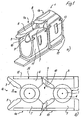
- FIG. 6 shows metal parts of a further connection device 10 for the insulation-penetrating connection of two conductors 102, which have one or more line conductors 103 and a conductor insulation 104 surrounding the line conductor (s) 103.
- the connecting device has a double cutting and contact spring 107 for connecting two conductors 102, which consists of three parallel to each other and in a plane or substantially in a plane adjacent legs 105, 106, 107.
- a contact slot 108, 109 is respectively formed on both sides of the middle leg 106, ie there is a first contact slot 108 between the left leg 105 and the middle leg 106 in FIG. 6a and a second contact slot 109 between the right leg 107 in FIG. 6a and the middle leg 106.
- the three legs 105, 106, 107 may be formed as free ends of a higher-level busbar 110, which is provided at its free end with the contact slots 108, 109.
- the busbar 110 may be bent in side view L, U (FIG. 6a) or Z-shaped.
- the legs 105, 106, 107 open like a mouth, so that on the one hand a first mouth region 111 in front of the first contact slot 108 and on the other hand, a second mouth region 112 is formed in front of the second contact slot 109.
- the legs 105, 106, 107 are provided with cutting edges 113 for penetrating the conductor insulation.
- the middle leg 106 in this case has at its free end a tapered shape, as it defines in a double function on both sides in each case one of the mouth regions 111, 102 and there severed the conductor insulation.
- the mouth areas can be arranged offset in the conductor insertion direction X, as seen in Figure 6, to each other. It is also conceivable that the conductors 102 in the inserted state are also arranged offset in relation to one another in the double cutting and contact spring 117 in order to further reduce the required installation space width in the connected state (see also FIG. 6b).
- An over-spring 115 which is here U-shaped and whose ends are attached to the outer legs 105, 107 in recesses 114 thereof, increases the contact force on both conductors. 2
- outer legs 105, 107 may also be connected to one another like a pipe-contact, although the arrangement of FIG. 1 with over-spring 115 is preferred.
- actuating element 118 For switching on and switching off Fig. 7 is preferably an actuating element 118.
- the preferred actuating element is designed as a slide element, which is guided in a corresponding free space of an electrical device, in particular a terminal or the like. Slidably. It has either an elongate conductor insertion opening (not shown here) designed for receiving two conductors or two or more conductor insertion openings 119, 120 (corresponding to FIG. 6) arranged laterally next to one another in relation to the conductor insertion direction. Lateral webs 121 serve to guide in a superordinate housing of a connection terminal (not shown here).
- the free space 122 serves to receive the legs 105, 106, 107. The free end of the ladder lays in each case against a lower stop 123.
- the actuating element 118 is preferably one or more preferably open on both sides, so that it builds very narrow.
Landscapes
- Coupling Device And Connection With Printed Circuit (AREA)
- Connections By Means Of Piercing Elements, Nuts, Or Screws (AREA)
- Connections Arranged To Contact A Plurality Of Conductors (AREA)
- Manufacturing Of Electrical Connectors (AREA)
Description
- Die Erfindung betrifft eine Anschlußvorrichtung nach dem Oberbegriff des Anspruches 1.
- Aus dem Stand der Technik sind isolationsdurchdringende Anschlussvorrichtungen bekannt, welche eine Schneid- und Kontaktfeder mit zwei federnden Kontaktschenkeln aufweisen, die einen Kontaktschlitz begrenzen, wobei eine U-förmige Über- oder Kraftfeder die beiden Schenkel einfaßt. Eine derartige Lösung zeigt beispielsweise die DE 197 32 182 C1. Bekannt ist es auch, in eine derartige Anschlußvorrichtung den Leiter mittels eines Betätigungselementes, insbesondere eines Schieberelementes einzuführen.
- Ebenfalls bekannt sind aus dem Stand der Technik Anschlußvorrichtungen, bei denen der Schneidklemmkontakt als Rohrkontakt ohne Über- oder Kraftfeder ausgebildet ist.
- Aus der gattungsgemäßen US 5 788 539 ist es zudem bekannt, das Betätigungselement mit zwei nebeneinander liegenden, d.h. senkrecht zur Leitereinführrichtung angeordneten Leitereinführöffnungen zu versehen, so daß nur mit einem Betätigungselement zwei nebeneinander angeordnete Einzelanschlüsse bzw. Einzelkontakte kontaktierbar sind.
- Aus der EP 1 152 488 A1 ist ferner bekannt, in einen längeren Schlitz eines IDC-Kontaktes zwei Leiter hintereinander einzuführen. In diesem Zusammenhang sei auch auf die DE 196 27 209 C2 verwiesen.
- Gegenüber dem gattungsgemäßen Stand der Technik ist es die Aufgabe der Erfindung, die benötigte Bauraumlänge und/oder Bauraumbreite von Anschlussvorrichtungen zu verringern, bei welchen in Leitereinführrichtung mehr als ein Leiter kontaktiert werden soll. Derartige Anschlußvorrichtungen sollen insbesondere für Reihenklemmen, aber auch elektrische Geräte sonstiger Art wie Schütze o.dgl. geeignet sein.
- Eine Anschlussvorrichtung gemäß dem Oberbegriff von Anspruch 1 ist in EP-A1-1 191 634 gezeigt.
- Die Erfindung löst die Aufgabe durch den Gegenstand des Anspruches 1.
- Durch die vorstehenden Maßnahmen wird es in besonderer Weise möglich, mit nur einem Betätigungselement gleichzeitig in Leitereinfiihrrichtung zwei Leiter gleichen oder verschiedenen Durchmessers in entweder einen Mehrfachanschluß bzw. Mehrfachkontakt oder zwei Einzelanschlüsse bzw. zwei Einzelkontakte einzuführen. Diese Maßnahme ist insbesondere bei Reihenklemmen u.dgl. von Interesse, bei denen bei geringer Bauraumbreite mehrere leitend miteinander verbundene Anschlusskontakte hintereinander (z.B. senkrecht zu einer Tragschiene) vorzusehen sind. Sie eignet sich aber auch für andere elektrische Geräte wie Schütze u.dgl., bei denen ähnliche Probleme bestehen.
- Weitere vorteilhafte Ausgestaltungen sind den übrigen Unteransprüchen zu entnehmen.
- Nachfolgend wird die Erfindung unter Bezug auf die Zeichnung anhand von Ausführungsbeispielen näher erläutert. Es zeigt:
- Figur 1a, b
- eine perspektivische Ansicht und eine Draufsicht auf Metallteile eines ersten Ausführungsbeispiels der Erfmdung;
- Figur 2a, b
- eine perspektivische Ansicht und eine Draufsicht auf Metallteile eines zweiten Ausführungsbeispiels der Erfindung;
- Figur 3a, b
- eine Seitenansicht und eine Draufsicht eines dritten Ausführungsbeispiels der Erfindung;
- Figur 3c
- eine Draufsicht auf Metallteile eines vierten Ausführungsbeispiels der Erfindung;
- Figur 4a-c
- Seitenansichten eines Beispiels in unbeschaltetem und beschaltetem Zustand und eine perspektivische Ansicht der Metallteile des vierten Ausführungsbeispiels der Erfindung; und
- Figur 5a, b
- Seitenansichten eines fünften Ausführungsbeispiels der Erfindung in unbeschaltetem (Figur 5a) und im beschalteten (Figur 5b) Zustand;
- Fig. 6 a, b
- eine perspektivische Ansicht und eine Draufsicht auf Metallteile eines Beispiels; und
- Fig. 7
- ein Betätigungselement für das Beispiel aus Fig. 6.
- Fig. 4a-c, Fig 5a und 5b und Fig. 6a und 6b zeigen keine Ausführungsbeispiele der Erfindung, sondern Beispiele, welche das Verständnis der Erfindung erleichtern sollen.
- Fig. 1 zeigt Metallteile einer Anschlussvorrichtung 1 mit hier zwei Einzelanschlüssen 1a und 1b zum Anschluss von nichtabisolierten Leiterenden von Leitern 2, welche eine oder mehrere Leitungsader(n) 3 aufweisen sowie eine die Leitungsader(n) 3 umgebende Leiterisolierung 4.
- Die Einzelanschlüsse 1a und 1b weisen jeweils eine Schneid- und Kontaktfeder 5 auf, welche aus zwei metallenen Schenkeln 6, 7 bestehen, zwischen denen ein Kontaktschlitz 8 ausgebildet ist und die entweder in einer Ebene liegen oder leicht winklig zueinander ausgerichtet sind.
- An ihren freien Enden weiten sich die Schenkel 6, 7 mündungsartig auf. Schneidkanten 9 im Mündungsbereich 10 erlauben das Durchtrennen der Leiterisolierung 4 beim Einführen des Leiters 2 in den Kontaktschlitz 8. Eine U-förmige Überfeder 11, wie sie aus der DE 197 32 182 C2 bekannt ist und die hier in Randausnehmungen 20 der Schenkel 6, 7 eingreift, erhöht die Kontaktkraft auf den im Kontaktschlitz 8 befindlichen Leiter 2 und stellt bei geringstem Bauraumbedarf einen dauerhaft guten Kontakt sicher.
- Die Schenkel 6, 7 sind hier als die freien Enden einer gemeinsamen Stromschiene 12 ausgebildet, welche hinter der Überfeder 11 im Gehäuse nach unten verläuft. Die beiden Stromschienen 12 der Einzelanschlüsse 1a, 1b können an beliebiger Stelle, z.B. unterhalb der Überfedern zusammengeheftet werden.
- Schlitze oder Aussparungen 13 in den senkrecht zu den Schenkeln 6, 7 verlaufenden Seitenwandungen der U-förmigen Überfeder 11 ermöglichen die Realisierung besonders schmaler Bauformen, da die Isolierung des Leiters seitlich in den Schlitz hineinragen kann.
- Nach Fig. 1 wird dadurch ein Doppelanschluss für zwei Leiter 2 realisiert, dass zwei der Anschlussvorrichtungen 1a, 1,b unmittelbar hintereinander angeordnet sind, und zwar derart, dass die Schlitze 8 der beiden Einzelanschlüsse 1a und 1b miteinander fluchten, so dass ein Leiter 2 durch den ersten Einzelanschluss 1a hindurch in den zweiten Einzelanschluss 1b führbar ist.
- Die freien Enden der Schenkel 6, 7 des in Leitereinfilhrrichtung X hinteren Einzelanschlusses 1b liegen nach Fig. 1 in ihrem Mündungsbereich 10 auf den hinteren Enden der Schenkel 6, 7 der ersten bzw. vorderen Einzelanschlusses 1a auf.
- Durch den hieraus resultierenden leichten Höhenversatz der beiden Schneid- und Kontaktfedern 5 beiden Einzelanschlüsse wird die Leiterisolierung 4 eines Leiters, die bereits beim Einführen in die erste Anschlussvorrichtung erstmals durchtrennt wurde, weiter aufgeweitet und/oder ein weiteres Mal durchtrennt. Durch den Überlapp wird ferner ausgeschlossen, dass der Leiter 2 beim Einführen an den Schenkeln 6, 7 der hinteren Anschlussvorrichtung vorbei aus dem Doppelanschluss herausrutscht.
- Durch die getrennte Ausgestaltung der beiden Einzelanschlüsse 1a, 1b der Anschlussvorrichtung 1 wird einerseits sicher die Isolierung beider Leiter 2 durchtrennt. Darüber hinaus wird aber auch eine besonders gute Kontaktierung beider Leiter 2 sichergestellt. Würde anstelle zwei getrennter Einzelanschlüsse 1a und b ein einziger, längerer Einzelanschluss mit entsprechend längerer Schneid- und Kontaktfeder 5 eingesetzt, die gleichzeitig zwei Leiter 2 kontaktiert, bestünde die theoretische Möglichkeit, dass einer der beiden Leiter 2 nur ungenügend kontaktiert wird, da der hintere Leiter 2 die beiden Schenkel 6, 7 auseinander drücken würde, so dass der Kontaktschlitz 8 im Bereich des vorderen Leiters möglicherweise breiter wäre als der Durchmesser des dort zu kontaktierenden Leiters.
- Ein weiterer Vorteil der Anordnung mit zwei hinsichtlich der Metallteile voneinander weitgehend getrennter Einzelanschlüsse 1a, 1b besteht in der Möglichkeit, problemlos Leiter 2 verschiedensten Durchmessers in den beiden Einzelanschlüssen 1a, 1b kontaktieren zu können, da jeder der beiden Leiter 2 unabhängig vom jeweils anderen Leiter 2 beschaltet wird.
- Gegenüber einer Anordnung aus zwei getrennten Einzelanschlüssen, deren Schneid- und Kontaktfedern 5 sich nicht überlappen, wird darüber hinaus in vorteilhafter Weise die benötigte Bauraumlänge besonders deutlich nochmals verringert.
- Das Prinzip der Fig. 1 lässt sich theoretisch auch auf drei oder gar mehr Einzelanschlüsse erweitern.
- Nach Fig. 1 und 3a überlappen sich die zwei Schneid- und Kontaktfedern 5 der in Leitereinführrichtung (X) hintereinander angeordneten Einzelanschlüsse 1a, 1b so teilweise, dass ein Leiter senkrecht zur Leitereinführrichtung theoretisch auch direkt von oben in den Mündungsbereich 10 im Bereich der hinteren Schneid- und Kontaktfeder 5 führbar ist.
- Nach Fig. 2 erstreckt sich dagegen die erste Schneid- und Kontaktfedern 5 durch die hintere Überfeder 11 des hinteren Einzelanschlusses 1 hindurch. Dabei weist sie - um die Kontaktierung des zweiten Leiters nicht zu behindern - im Kontaktbereich der in Leitereinführrichtung X hinteren Schneid- und Kontaktvorrichtung 1a seitliche Aussparungen 19 in den Schenkeln 6, 7 der Schneid- und Kontaktfeder 5 auf.
- Zum Be- und Entschalten dient nach Fig. 3 (oder auch Fig. 1 und 2) vorzugsweise ein Betätigungselement 14. Das bevorzugte Betätigungselement 14 ist hier als Schieberelement ausgebildet, welches in einem entsprechenden Freiraum eines elektrischen Gerätes, insbesondere einer Reihenklemme oder dgl. verschieblich geführt ist.
- Es weist entweder eine längliche und für die Aufnahme von zwei Leitern ausgelegte Leitereinfiihröffnung (hier nicht dargestellt) oder zwei miteinander in der Leitereinfiihrrichtung x miteinander fluchtende Leitereinführöffnungen 15, 16 auf.
- Bevorzugt weist es ferner einseitig oder beidseitig einen Zapfen oder Steg 21 auf, der zum Eingriff in eine korrespondierende Ausnehmung eines die Anschlussvorrichtung aufnehmenden Isolierstoffgehäuses ausgelegt ist und der dazu dient, die Verschieblichkeit des Betätigungselementes am Isolierstoffgehäuse zu sichern.
- Die Leitereinführöffnungen 15, 16 erstrecken sich über die Ebene(n) der Schneid- und Kontaktfedern 5 hinaus, in deren Höhe das Betätigungselement 14 zudem einen korrespondierenden Schlitz 17 aufweist, mit dem es über die Schneid- und Kontaktfedern 5 führbar ist. Derart wird nicht nur die benötigte Baulänge gegenüber einer Ausgestaltung mit zwei getrennten Betätigungselementen klar verringert sondern auch der eigentliche Be- und Entschaltvorgang für zwei Leiter 2 vereinfacht, indem gleichzeitig mit nur einer Bewegung zwei (oder entsprechend mehr) Leiter 2 schaltbar sind.
- Die Leitereinführöffnungen 15, 16 können an die Geometrie der Metallteile angepasst werden, d.h., sie können entweder derart beabstandet werden, dass die einzelnen Leiter direkt in die Mündungsbereiche von zwei Einzelanschlüssen - egal ob diese einander etwas mehr oder weniger überlappen (Fig. 2, 3a) oder nicht (Fig. 3b) - oder gemeinsam vor den vorderen Einzelanschluss von zwei Einzelanschlüssen 1a, 1b führbar sind.
- Die Einzelanschlüsse 1a und 1b oder der Mehrfachanschluss bilden mit dem Betätigungselement 14 die als Doppelanschluss ausgebildete Anschlußvorrichtung 1 aus.
- Fig. 4 zeigt ein Beispiel, bei welchem eine längere Schneid- und Kontaktfeder 5 eingesetzt wird, in welche hintereinander zwei Leiter 2 einführbar sind. Die entsprechend ebenfalls längere Überfeder 11 weist zusätzlichen seitliche Schlitze 22 auf, um die Federwirkung der Überfeder auf die beiden Leiter 2 in den beiden zur Kontaktierung der Leiter 2 vorgesehenen Bereichen soweit wie möglich voneinander zu trennen. Anstelle einer längeren Überfeder 11 mit Schlitz könnten auch zwei kürzere Überfedern 11 an der Schneid- und Kontaktfeder angeordnet sein (hier nicht dargestellt).
- Die Schenkel 6, 7 müssen im Bereich des Schlitze 8 zwischen ihnen nicht unbedingt parallel zueinander verlaufen sondern durch entsprechende Auslegung könnte auch ein sich in Einführrichtung verjüngender (siehe Fig. 4c) oder u.U. aufweitender Keil ausgebildet werden, was die Kontaktierung von Leitern mit verschiedenen Durchmessern erleichtert.
- Fig. 5 unterscheidet sich von den vorhergehenden Anwendungen dadurch, dass die Metallteile zweier Einzelanschlüsse 1a, 1b zwar miteinander fluchten aber zueinander mit deutlichem Höhenversatz angeordnet sind. Dennoch ist nur ein Betätigungselement 14 vorgesehen, welches durch seine stufenartige Auslegung mit zwei stufenartig zueinander versetzten Leitereinfiihröffnungen 15, 16 dieser veränderten Anordnung Rechnung trägt. Auch hier besteht der Vorteil der Möglichkeit zu einer einfachen Beschaltung mit zwei Leitern mit nur einer Bewegung eines Schraubendrehers oder dgl. und einer in Einführrichtung kompakten Auslegung. Der Bauraumbedarf gegenüber einer Ausgestaltung mit zwei Betätigungselementen wird verringert.
- Die Betätigungselemente 14 mit den Leitern 2 können beispielsweise an Ansätzen oder mittels an Widerlagern in einem übergeordneten Gehäuse abgestützten Werkzeugen wie Schraubendrehen bewegt werden (hier nicht dargestellt).
- Fig. 6 zeigt Metallteile einer weiteren Anschlussvorrichtung 10 zum isolationsdurchdringenden Anschluss von zwei Leitern 102, welche eine oder mehrere Leitungsader(n) 103 aufweisen sowie eine die Leitungsader(n) 103 umgebende Leiterisolierung 104.
- Die Anschlußvorrichtung weist eine Doppel-Schneid- und Kontaktfeder 107 zum Anschluss von zwei Leitern 102 auf, welche aus drei parallel zueinander und in einer Ebene oder im wesentlichen in einer Ebene nebeneinander angeordneten Schenkeln 105, 106, 107 besteht. Beidseits des mittleren Schenkels 106 ist jeweils ein Kontaktschlitz 108, 109 ausgebildet, d.h., es besteht ein erster Kontaktschlitz 108 zwischen dem in Fig. 6a linken Schenkel 105 und dem mittleren Schenkel 106 und ein zweiter Kontaktschlitz 109 zwisehen dem in Fig. 6a rechten Schenkel 107 und dem mittleren Schenkel 106.
- Die drei Schenkel 105, 106, 107 können als freie Enden einer übergeordneten Stromschiene 110 ausgebildet sein, welche an ihrem freien Ende mit den Kontaktschlitzen 108, 109 versehen ist. Die Stromschiene 110 kann in Seitenansicht L-, U- (Fig. 6a) oder Z-förmig gebogen sein.
- An ihren freien Enden weiten sich die Schenkel 105, 106, 107 mündungsartig auf, so dass einerseits ein erster Mündungsbereich 111 vor dem ersten Kontaktschlitz 108 und andererseits ein zweiter Mündungsbereich 112 vor dem zweiten Kontaktschlitz 109 ausgebildet ist.
- In den Mündungsbereichen 111, 112 sind die Schenkel 105, 106, 107 mit Schneidkanten 113 zum Durchdringen der Leiterisolierung versehen. Der mittlere Schenkel 106 weist dabei an seinem freien Ende eine spitz zulaufende Form auf, da er in Doppelfunktion zu beiden Seiten hin jeweils einen der Mündungsbereiche 111, 102 begrenzt und dort die Leiterisolierung durchtrennt.
- Die Mündungsbereiche können in Leitereinführrichtung X, wie in Figur 6 erkennbar, versetzt zueinander angeordnet sein. Es ist ferner denkbar, dass die Leiter 102 im eingeführten Zustand ebenfalls in der Doppel-Schneid- und Kontaktfeder 117 versetzt zueinander angeordnet sind, um die benötigte Bauraumbreite im beschalteten Zustand noch weiter zu verringern (siehe auch Fig. 6b).
- Eine Überfeder 115, welche hier U-förmig ausgebildet ist und deren Enden an den äußeren Schenkel 105, 107 in Aussparungen 114 desselben befestigt sind, erhöht die Kontaktkraft auf beide Leiter 2.
- Alternativ könnten die äußeren Schenkel 105, 107 auch rohrkontaktartig miteinander verbunden sein, obwohl die Anordnung der Fig. 1 mit Überfeder 115 bevorzugt wird.
- Schlitze oder Aussparungen in den senkrecht zu den Schenkeln 106, 107 verlaufenden Seitenwandungen der U-förmigen Überfeder 115 ermöglichen die Realisierung besonders schmaler Bauformen, da die Isolierung des Leiters seitlich in den Schlitz hineinragen kann (hier nicht dargestellt).
- Zum Be- und Entschalten dient nach Fig. 7 vorzugsweise ein Betätigungselement 118. Das bevorzugte Betätigungselement ist als Schieberelement ausgebildet, welches in einem entsprechenden Freiraum eines elektrischen Gerätes, insbesondere einer Reihenklemme oder dgl. verschieblich geführt ist. Es weist entweder eine längliche und für die Aufnahme von zwei Leitern ausgelegte Leitereinführöffnung (hier nicht dargestellt) oder zwei oder mehr relativ zur Leitereinführrichtung seitlich nebeneinander angeordnete Leitereinführöffnungen 119, 120 (entsprechend zu Fig. 6) auf. Seitliche Stege 121 dienen der Führung in einem übergeordneten Gehäuse einer Anschlussklemme (hier nicht dargestellt). Der Freiraum 122 dient der Aufnahme der Schenkel 105, 106, 107. Das freie Ende der Leiter legt sich jeweils gegen einen unteren Anschlag 123. Das Betätigungselement 118 steht bevorzugt ein- oder besonders bevorzugt beidseitig offen, so dass es sehr schmal baut.
-
- Anschlussvorrichtung
- 1
- Einzelanschlüsse
- 1a und 1b
- Leiter
- 2
- Leitungsader(n)
- 3
- Leiterisolierung
- 4
- Schneid- und Kontaktfeder
- 5
- Schenkel
- 6, 7
- Schlitz
- 8
- Schneidkanten
- 9
- Mündungsbereich
- 10
- Überfeder
- 11
- Stromschiene
- 12
- Aussparungen
- 13
- Betätigungselement
- 14
- Leitereinführöffnungen
- 15, 16
- Schlitz
- 17
- Ausnehmung
- 19
- Randausnehmungen
- 20
- Steg
- 21
- Schlitze
- 22
- Anschlussvorrichtung
- 101
- Leiter
- 102
- Leitungsader(n)
- 103
- Leiterisolierung
- 104
- Schenkel
- 105, 106, 107
- Kontaktschlitz
- 108, 109
- Stromschiene
- 110
- Mündungsbereich
- 111
- Mündungsbereich
- 112
- Schneidkanten
- 113
- Aussparungen
- 114
- Überfeder
- 115
- Schneid- und Kontaktfeder
- 116
- Schneid- und Kontaktfeder
- 117
- Betätigungselement
- 118
- Leitereinfiihröffnungen
- 119, 120
- Stege
- 121
- Freiraum
- 122
- Anschlag
- 123
Claims (6)
- Anschlussvorrichtung (1) mita) wenigstens einem Mehrfachanschluss bzw. -kontakt oder mehreren Einzelanschlüssen bzw. -kontakten (1a) und (1b) zum isolationsdurchdringenden Anschluss von nichtabisolierten Leiterenden von wenigstens zwei Leitern (2), welche jeweils eine oder mehrere Leitungsader(n) (3) sowie eine die Leitungsader(n)(3)umgebende Leiterisolierung (4) aufweisen,b) wobei jeder Mehrfach- oder Einzelanschluss (1a und 1b) eine Schneid- und Kontaktfeder (5) aufweist, welche aus zwei metallenen Schenkeln (6, 7) besteht, zwischen denen ein Kontaktschlitz (8) ausgebildet ist,c) wobei jeder Leiter mit einem Betätigungselement (14) in den Kontaktschlitz (8) und aus diesem heraus bewegbar ist,e) wobei in Leitereinführrichtung die Metallteile von zwei Einzelanschlüssen (1a, 1b), d.h. zumindest zwei Schneid- und Kontaktfedern (5), miteinander fluchtend hintereinander angeordnet sind,f) wobei die Schneid- und Kontaktfedern (5) jeweils mit einer Überfeder (11) versehen sind, undg) wobei die wenigstens eine Überfeder (11) Aussparungen (13) aufweist und/oder seitlich geschlitzt ausgelegt ist,dadurch gekennzeichnet, dass das Betätigungselement (14) wenigstens zwei miteinander in Leitereinführrichtung fluchtende Leitereinführöffnungen (15, 16) aufweist, d) wobei das Betätigungselement (14) als Schieberelement ausgebildet ist.
- Anschlussvorrichtung nach einem der vorstehenden Ansprüche, dadurch gekennzeichnet, dass sich die zwei Schneid- und Kontaktfedern (5) der in Leitereinführrichtung (X) hintereinander angeordneten Einzelanschlüsse (1a, 1b) teilweise überlappen.
- Anschlussvorrichtung nach einem der vorstehenden Ansprüche, dadurch gekennzeichnet, dass sich die zwei Schneid- und Kontaktfedern (5) der in Leitereinführrichtung (X) hintereinander angeordneten Einzelanschlüsse (1a, 1b) so teilweise überlappen, dass beide Leiter durch die vordere Schneid- und Kontaktfeder (5) hindurch in die hintere Schneid- und Kontaktfeder (5) führbar sind.
- Anschlussvorrichtung nach einem der vorstehenden Ansprüche, dadurch gekennzeichnet, dass sich die zwei Schneid- und Kontaktfedern (5) der in Leitereinfiihrrichtung (X) hintereinander angeordneten Einzelanschlüsse (1a, 1b) so teilweise überlappen, dass ein Leiter senkrecht zur Leitereinführrichtung auch direkt von oben in den Mündungsbereich (10) der hinteren Schneid- und Kontaktfeder (5) führbar ist.
- Anschlussvorrichtung nach einem der vorstehenden Ansprüche, dadurch gekennzeichnet, dass die zwei Einzelanschlüsse (1a, 1b) mit einem Höhenversatz angeordnet sind und dass die zwei Leitereinführöffnungen (15, 16) des Betätigungselements (14) einen korrespondierenden Höhenversatz aufweisen.
- Anschlußvorrichtung nach einem der vorstehenden Ansprüche, dadurch gekennzeichnet, daß sich der Kontaktschlitz in oder gegen die Leitereinführrichtung verjüngt.
Applications Claiming Priority (4)
| Application Number | Priority Date | Filing Date | Title |
|---|---|---|---|
| DE20308629U DE20308629U1 (de) | 2003-06-03 | 2003-06-03 | Anschlußvorrichtung zum isolationsdurchdringenden Anschluß von mehreren Leitern |
| DE20308630U DE20308630U1 (de) | 2003-06-03 | 2003-06-03 | Anschlußvorrichtung mit isolationsdurchdringendem Anschluß von wenigsten zwei Leitern |
| DE20308630U | 2003-06-03 | ||
| DE20308629U | 2003-06-03 |
Publications (3)
| Publication Number | Publication Date |
|---|---|
| EP1484818A2 EP1484818A2 (de) | 2004-12-08 |
| EP1484818A3 EP1484818A3 (de) | 2005-01-12 |
| EP1484818B1 true EP1484818B1 (de) | 2006-12-27 |
Family
ID=33160877
Family Applications (1)
| Application Number | Title | Priority Date | Filing Date |
|---|---|---|---|
| EP04012730A Expired - Lifetime EP1484818B1 (de) | 2003-06-03 | 2004-05-28 | Anschlussvorrichtung zum isolationsdurchdringenden Anschluss von wenigstens zwei Leitern |
Country Status (3)
| Country | Link |
|---|---|
| EP (1) | EP1484818B1 (de) |
| AT (1) | ATE349783T1 (de) |
| DE (1) | DE502004002415D1 (de) |
Families Citing this family (3)
| Publication number | Priority date | Publication date | Assignee | Title |
|---|---|---|---|---|
| DE102008026470A1 (de) * | 2008-06-03 | 2010-02-04 | Bticino S.P.A. | Druckstück für eine Anschlussklemme |
| FR3029698B1 (fr) | 2014-12-05 | 2018-03-02 | Legrand France | Element de connexion electrique a percage de gaine isolante d'un fil electrique |
| FR3113544B1 (fr) | 2020-08-20 | 2022-09-02 | Berker Gmbh & Co Kg | Borne de connexion auto-dénudante d’un conducteur électrique isolé |
Family Cites Families (14)
| Publication number | Priority date | Publication date | Assignee | Title |
|---|---|---|---|---|
| US3897128A (en) * | 1974-03-25 | 1975-07-29 | Amp Inc | Pre-insulated connecting device for a plurality of wires having insulation displacing features |
| US4223971A (en) * | 1979-01-05 | 1980-09-23 | Amp Incorporated | Electrical wiring assembly and method |
| FR2455370A1 (fr) * | 1979-04-26 | 1980-11-21 | Bunker Ramo | Element de contact pour raccordement sans denudage de fils electriques |
| GB2075279B (en) * | 1980-05-02 | 1984-02-08 | Egerton A C Ltd | Terminal connector |
| DE3627333A1 (de) * | 1986-08-12 | 1988-02-18 | Baer Elektrowerke Gmbh & Co Kg | Elektrischer schalter |
| FR2725836A1 (fr) * | 1994-10-17 | 1996-04-19 | Lacroix Jacques | Dispositif de connexion de fils conducteurs gaines |
| DE29603585U1 (de) * | 1996-02-28 | 1997-06-26 | Lumberg Karl Gmbh & Co | Steckverbinder |
| US5860829A (en) * | 1996-05-31 | 1999-01-19 | The Whitaker Corporation | Cross connect terminal block |
| DE19627209C1 (de) * | 1996-07-05 | 1997-10-23 | Siemens Ag | Anschlußvorrichtung für nichtabisolierte Leiter |
| US6074240A (en) * | 1996-10-16 | 2000-06-13 | Marconi Communications Inc. | Terminal block |
| DE19732182C1 (de) * | 1997-07-25 | 1999-03-25 | Quante Ag | Schneidklemm-Kontakt sowie Anschlußleiste oder -modul und Reihenklemme mit einem Schneidklemm-Kontakt |
| DE69927662T2 (de) * | 1999-01-15 | 2006-07-20 | The Whitaker Corp., Wilmington | Verbinder zum Abschliessen von Fernmeldekabeln |
| US6080006A (en) * | 1999-05-26 | 2000-06-27 | Broder; Eric S. | Insulated connector for electrical conductors |
| ATE286628T1 (de) * | 2000-09-25 | 2005-01-15 | Weidmueller Interface | Reihenklemme mit schneidkontakten und anschlussvorrichtung |
-
2004
- 2004-05-28 DE DE502004002415T patent/DE502004002415D1/de not_active Expired - Lifetime
- 2004-05-28 EP EP04012730A patent/EP1484818B1/de not_active Expired - Lifetime
- 2004-05-28 AT AT04012730T patent/ATE349783T1/de not_active IP Right Cessation
Also Published As
| Publication number | Publication date |
|---|---|
| EP1484818A3 (de) | 2005-01-12 |
| DE502004002415D1 (de) | 2007-02-08 |
| ATE349783T1 (de) | 2007-01-15 |
| EP1484818A2 (de) | 2004-12-08 |
Similar Documents
| Publication | Publication Date | Title |
|---|---|---|
| EP3507866B1 (de) | Leiteranschlussklemme | |
| EP1253670B1 (de) | Federklemme und Federklemmenreihung | |
| EP1515397B1 (de) | Anschlussvorrichtung zum Direktsteckanschluss von Leiterenden | |
| DE10351289B4 (de) | Steckbrücke für elektrische Anschluß- und/oder Verbindungsklemmen | |
| DE4433983A1 (de) | Anschlußklemme für elektrische Installationen | |
| DE102011056043B4 (de) | Stromschienenabgriffelement | |
| DE20114612U1 (de) | Reihenklemme mit Schneidkontakten und Anschlußvorrichtung | |
| DE4102784C2 (de) | Anschlußklemme | |
| DE102009030645B4 (de) | Brückerelement und Set aus zumindest einem Klemmelement und Brückerelement | |
| DE112008004167B4 (de) | Verbindervorrichtung und Steuerungszentrum mit einer Funktionseinheit mit einer solchen Verbindervorrichtung | |
| DE29719177U1 (de) | Reihenklemmenanordnung | |
| DE10134417C1 (de) | Elektrische Anschluß- oder Verbindungseinrichtung | |
| EP0090317A2 (de) | Vorrichtung zum Anschluss von draht- oder litzenförmigen elektrischen Leitern an Kontaktorgane | |
| DE20305313U1 (de) | Anschlußeinrichtung | |
| EP1331693B1 (de) | Anschlussklemmenleitse | |
| DE20211513U1 (de) | Anschlußvorrichtung mit Klemmfeder | |
| EP1020954B1 (de) | Elektrische Anschlussklemme | |
| EP1484818B1 (de) | Anschlussvorrichtung zum isolationsdurchdringenden Anschluss von wenigstens zwei Leitern | |
| EP1432076B1 (de) | Elektrische Verbindungsklemme, insbesondere Reihenklemme | |
| EP1472766A1 (de) | Anschluss- oder verteilvorrichtung für elektrische installationsgeräte | |
| DE10238852B3 (de) | Schaltgerät | |
| EP1587166B1 (de) | Verteilerleiste | |
| DE19607381C2 (de) | Steckverbinder | |
| EP4109684B1 (de) | Kontaktanordnung | |
| DE20308630U1 (de) | Anschlußvorrichtung mit isolationsdurchdringendem Anschluß von wenigsten zwei Leitern |
Legal Events
| Date | Code | Title | Description |
|---|---|---|---|
| PUAI | Public reference made under article 153(3) epc to a published international application that has entered the european phase |
Free format text: ORIGINAL CODE: 0009012 |
|
| PUAL | Search report despatched |
Free format text: ORIGINAL CODE: 0009013 |
|
| AK | Designated contracting states |
Kind code of ref document: A2 Designated state(s): AT BE BG CH CY CZ DE DK EE ES FI FR GB GR HU IE IT LI LU MC NL PL PT RO SE SI SK TR |
|
| AX | Request for extension of the european patent |
Extension state: AL HR LT LV MK |
|
| AK | Designated contracting states |
Kind code of ref document: A3 Designated state(s): AT BE BG CH CY CZ DE DK EE ES FI FR GB GR HU IE IT LI LU MC NL PL PT RO SE SI SK TR |
|
| AX | Request for extension of the european patent |
Extension state: AL HR LT LV MK |
|
| 17P | Request for examination filed |
Effective date: 20050125 |
|
| 17Q | First examination report despatched |
Effective date: 20050329 |
|
| AKX | Designation fees paid |
Designated state(s): AT BE BG CH CY CZ DE DK EE ES FI FR GB GR HU IE IT LI LU MC NL PL PT RO SE SI SK TR |
|
| GRAP | Despatch of communication of intention to grant a patent |
Free format text: ORIGINAL CODE: EPIDOSNIGR1 |
|
| GRAS | Grant fee paid |
Free format text: ORIGINAL CODE: EPIDOSNIGR3 |
|
| GRAA | (expected) grant |
Free format text: ORIGINAL CODE: 0009210 |
|
| AK | Designated contracting states |
Kind code of ref document: B1 Designated state(s): AT BE BG CH CY CZ DE DK EE ES FI FR GB GR HU IE IT LI LU MC NL PL PT RO SE SI SK TR |
|
| PG25 | Lapsed in a contracting state [announced via postgrant information from national office to epo] |
Ref country code: IT Free format text: LAPSE BECAUSE OF FAILURE TO SUBMIT A TRANSLATION OF THE DESCRIPTION OR TO PAY THE FEE WITHIN THE PRESCRIBED TIME-LIMIT;WARNING: LAPSES OF ITALIAN PATENTS WITH EFFECTIVE DATE BEFORE 2007 MAY HAVE OCCURRED AT ANY TIME BEFORE 2007. THE CORRECT EFFECTIVE DATE MAY BE DIFFERENT FROM THE ONE RECORDED. Effective date: 20061227 Ref country code: RO Free format text: LAPSE BECAUSE OF FAILURE TO SUBMIT A TRANSLATION OF THE DESCRIPTION OR TO PAY THE FEE WITHIN THE PRESCRIBED TIME-LIMIT Effective date: 20061227 Ref country code: CZ Free format text: LAPSE BECAUSE OF FAILURE TO SUBMIT A TRANSLATION OF THE DESCRIPTION OR TO PAY THE FEE WITHIN THE PRESCRIBED TIME-LIMIT Effective date: 20061227 Ref country code: DK Free format text: LAPSE BECAUSE OF FAILURE TO SUBMIT A TRANSLATION OF THE DESCRIPTION OR TO PAY THE FEE WITHIN THE PRESCRIBED TIME-LIMIT Effective date: 20061227 Ref country code: SI Free format text: LAPSE BECAUSE OF FAILURE TO SUBMIT A TRANSLATION OF THE DESCRIPTION OR TO PAY THE FEE WITHIN THE PRESCRIBED TIME-LIMIT Effective date: 20061227 Ref country code: NL Free format text: LAPSE BECAUSE OF FAILURE TO SUBMIT A TRANSLATION OF THE DESCRIPTION OR TO PAY THE FEE WITHIN THE PRESCRIBED TIME-LIMIT Effective date: 20061227 Ref country code: SK Free format text: LAPSE BECAUSE OF FAILURE TO SUBMIT A TRANSLATION OF THE DESCRIPTION OR TO PAY THE FEE WITHIN THE PRESCRIBED TIME-LIMIT Effective date: 20061227 Ref country code: IE Free format text: LAPSE BECAUSE OF FAILURE TO SUBMIT A TRANSLATION OF THE DESCRIPTION OR TO PAY THE FEE WITHIN THE PRESCRIBED TIME-LIMIT Effective date: 20061227 Ref country code: FI Free format text: LAPSE BECAUSE OF FAILURE TO SUBMIT A TRANSLATION OF THE DESCRIPTION OR TO PAY THE FEE WITHIN THE PRESCRIBED TIME-LIMIT Effective date: 20061227 Ref country code: PL Free format text: LAPSE BECAUSE OF FAILURE TO SUBMIT A TRANSLATION OF THE DESCRIPTION OR TO PAY THE FEE WITHIN THE PRESCRIBED TIME-LIMIT Effective date: 20061227 |
|
| REG | Reference to a national code |
Ref country code: GB Ref legal event code: FG4D Free format text: NOT ENGLISH |
|
| RIN1 | Information on inventor provided before grant (corrected) |
Inventor name: DIEKMANN, TORSTEN Inventor name: DIEKMANN, JOERG Inventor name: HANNING, WALTER Inventor name: HOEING, MICHAEL |
|
| REG | Reference to a national code |
Ref country code: IE Ref legal event code: FG4D Free format text: LANGUAGE OF EP DOCUMENT: GERMAN |
|
| REF | Corresponds to: |
Ref document number: 502004002415 Country of ref document: DE Date of ref document: 20070208 Kind code of ref document: P |
|
| PG25 | Lapsed in a contracting state [announced via postgrant information from national office to epo] |
Ref country code: BG Free format text: LAPSE BECAUSE OF FAILURE TO SUBMIT A TRANSLATION OF THE DESCRIPTION OR TO PAY THE FEE WITHIN THE PRESCRIBED TIME-LIMIT Effective date: 20070327 Ref country code: SE Free format text: LAPSE BECAUSE OF FAILURE TO SUBMIT A TRANSLATION OF THE DESCRIPTION OR TO PAY THE FEE WITHIN THE PRESCRIBED TIME-LIMIT Effective date: 20070327 |
|
| PG25 | Lapsed in a contracting state [announced via postgrant information from national office to epo] |
Ref country code: ES Free format text: LAPSE BECAUSE OF FAILURE TO SUBMIT A TRANSLATION OF THE DESCRIPTION OR TO PAY THE FEE WITHIN THE PRESCRIBED TIME-LIMIT Effective date: 20070407 |
|
| PG25 | Lapsed in a contracting state [announced via postgrant information from national office to epo] |
Ref country code: PT Free format text: LAPSE BECAUSE OF FAILURE TO SUBMIT A TRANSLATION OF THE DESCRIPTION OR TO PAY THE FEE WITHIN THE PRESCRIBED TIME-LIMIT Effective date: 20070528 |
|
| NLV1 | Nl: lapsed or annulled due to failure to fulfill the requirements of art. 29p and 29m of the patents act | ||
| GBV | Gb: ep patent (uk) treated as always having been void in accordance with gb section 77(7)/1977 [no translation filed] |
Effective date: 20061227 |
|
| EN | Fr: translation not filed | ||
| PLBE | No opposition filed within time limit |
Free format text: ORIGINAL CODE: 0009261 |
|
| STAA | Information on the status of an ep patent application or granted ep patent |
Free format text: STATUS: NO OPPOSITION FILED WITHIN TIME LIMIT |
|
| PG25 | Lapsed in a contracting state [announced via postgrant information from national office to epo] |
Ref country code: GB Free format text: LAPSE BECAUSE OF FAILURE TO SUBMIT A TRANSLATION OF THE DESCRIPTION OR TO PAY THE FEE WITHIN THE PRESCRIBED TIME-LIMIT Effective date: 20061227 |
|
| 26N | No opposition filed |
Effective date: 20070928 |
|
| BERE | Be: lapsed |
Owner name: WEIDMULLER INTERFACE G.M.B.H. & CO. KG Effective date: 20070531 |
|
| PG25 | Lapsed in a contracting state [announced via postgrant information from national office to epo] |
Ref country code: MC Free format text: LAPSE BECAUSE OF NON-PAYMENT OF DUE FEES Effective date: 20070531 |
|
| PG25 | Lapsed in a contracting state [announced via postgrant information from national office to epo] |
Ref country code: BE Free format text: LAPSE BECAUSE OF NON-PAYMENT OF DUE FEES Effective date: 20070531 |
|
| PG25 | Lapsed in a contracting state [announced via postgrant information from national office to epo] |
Ref country code: GR Free format text: LAPSE BECAUSE OF FAILURE TO SUBMIT A TRANSLATION OF THE DESCRIPTION OR TO PAY THE FEE WITHIN THE PRESCRIBED TIME-LIMIT Effective date: 20070328 Ref country code: FR Free format text: LAPSE BECAUSE OF FAILURE TO SUBMIT A TRANSLATION OF THE DESCRIPTION OR TO PAY THE FEE WITHIN THE PRESCRIBED TIME-LIMIT Effective date: 20070817 |
|
| PG25 | Lapsed in a contracting state [announced via postgrant information from national office to epo] |
Ref country code: AT Free format text: LAPSE BECAUSE OF NON-PAYMENT OF DUE FEES Effective date: 20070528 |
|
| PG25 | Lapsed in a contracting state [announced via postgrant information from national office to epo] |
Ref country code: FR Free format text: LAPSE BECAUSE OF FAILURE TO SUBMIT A TRANSLATION OF THE DESCRIPTION OR TO PAY THE FEE WITHIN THE PRESCRIBED TIME-LIMIT Effective date: 20061227 |
|
| REG | Reference to a national code |
Ref country code: CH Ref legal event code: PL |
|
| PG25 | Lapsed in a contracting state [announced via postgrant information from national office to epo] |
Ref country code: LI Free format text: LAPSE BECAUSE OF NON-PAYMENT OF DUE FEES Effective date: 20080531 Ref country code: CH Free format text: LAPSE BECAUSE OF NON-PAYMENT OF DUE FEES Effective date: 20080531 Ref country code: EE Free format text: LAPSE BECAUSE OF FAILURE TO SUBMIT A TRANSLATION OF THE DESCRIPTION OR TO PAY THE FEE WITHIN THE PRESCRIBED TIME-LIMIT Effective date: 20061227 |
|
| PG25 | Lapsed in a contracting state [announced via postgrant information from national office to epo] |
Ref country code: LU Free format text: LAPSE BECAUSE OF NON-PAYMENT OF DUE FEES Effective date: 20070528 Ref country code: CY Free format text: LAPSE BECAUSE OF FAILURE TO SUBMIT A TRANSLATION OF THE DESCRIPTION OR TO PAY THE FEE WITHIN THE PRESCRIBED TIME-LIMIT Effective date: 20061227 |
|
| PG25 | Lapsed in a contracting state [announced via postgrant information from national office to epo] |
Ref country code: TR Free format text: LAPSE BECAUSE OF FAILURE TO SUBMIT A TRANSLATION OF THE DESCRIPTION OR TO PAY THE FEE WITHIN THE PRESCRIBED TIME-LIMIT Effective date: 20061227 Ref country code: HU Free format text: LAPSE BECAUSE OF FAILURE TO SUBMIT A TRANSLATION OF THE DESCRIPTION OR TO PAY THE FEE WITHIN THE PRESCRIBED TIME-LIMIT Effective date: 20070628 |
|
| PGFP | Annual fee paid to national office [announced via postgrant information from national office to epo] |
Ref country code: DE Payment date: 20120523 Year of fee payment: 9 |
|
| PG25 | Lapsed in a contracting state [announced via postgrant information from national office to epo] |
Ref country code: DE Free format text: LAPSE BECAUSE OF NON-PAYMENT OF DUE FEES Effective date: 20131203 |
|
| REG | Reference to a national code |
Ref country code: DE Ref legal event code: R119 Ref document number: 502004002415 Country of ref document: DE Effective date: 20131203 |