EP1484818B1 - Dispositif de connexion pour le raccordement par perforation d'isolant d'ou moins deux conducteurs - Google Patents
Dispositif de connexion pour le raccordement par perforation d'isolant d'ou moins deux conducteurs Download PDFInfo
- Publication number
- EP1484818B1 EP1484818B1 EP04012730A EP04012730A EP1484818B1 EP 1484818 B1 EP1484818 B1 EP 1484818B1 EP 04012730 A EP04012730 A EP 04012730A EP 04012730 A EP04012730 A EP 04012730A EP 1484818 B1 EP1484818 B1 EP 1484818B1
- Authority
- EP
- European Patent Office
- Prior art keywords
- conductor
- contact
- cutting
- conductors
- spring
- Prior art date
- Legal status (The legal status is an assumption and is not a legal conclusion. Google has not performed a legal analysis and makes no representation as to the accuracy of the status listed.)
- Expired - Lifetime
Links
- 239000004020 conductor Substances 0.000 title claims abstract description 94
- 238000009413 insulation Methods 0.000 title claims abstract description 17
- 230000000149 penetrating effect Effects 0.000 title claims abstract description 4
- 238000003780 insertion Methods 0.000 claims abstract description 30
- 230000037431 insertion Effects 0.000 claims abstract description 30
- 239000002184 metal Substances 0.000 claims description 13
- 238000009434 installation Methods 0.000 description 4
- 238000006073 displacement reaction Methods 0.000 description 1
- 239000011810 insulating material Substances 0.000 description 1
- 230000005923 long-lasting effect Effects 0.000 description 1
Images


Classifications
-
- H—ELECTRICITY
- H01—ELECTRIC ELEMENTS
- H01R—ELECTRICALLY-CONDUCTIVE CONNECTIONS; STRUCTURAL ASSOCIATIONS OF A PLURALITY OF MUTUALLY-INSULATED ELECTRICAL CONNECTING ELEMENTS; COUPLING DEVICES; CURRENT COLLECTORS
- H01R4/00—Electrically-conductive connections between two or more conductive members in direct contact, i.e. touching one another; Means for effecting or maintaining such contact; Electrically-conductive connections having two or more spaced connecting locations for conductors and using contact members penetrating insulation
- H01R4/24—Connections using contact members penetrating or cutting insulation or cable strands
- H01R4/2416—Connections using contact members penetrating or cutting insulation or cable strands the contact members having insulation-cutting edges, e.g. of tuning fork type
- H01R4/2445—Connections using contact members penetrating or cutting insulation or cable strands the contact members having insulation-cutting edges, e.g. of tuning fork type the contact members having additional means acting on the insulation or the wire, e.g. additional insulation penetrating means, strain relief means or wire cutting knives
-
- H—ELECTRICITY
- H01—ELECTRIC ELEMENTS
- H01R—ELECTRICALLY-CONDUCTIVE CONNECTIONS; STRUCTURAL ASSOCIATIONS OF A PLURALITY OF MUTUALLY-INSULATED ELECTRICAL CONNECTING ELEMENTS; COUPLING DEVICES; CURRENT COLLECTORS
- H01R4/00—Electrically-conductive connections between two or more conductive members in direct contact, i.e. touching one another; Means for effecting or maintaining such contact; Electrically-conductive connections having two or more spaced connecting locations for conductors and using contact members penetrating insulation
- H01R4/24—Connections using contact members penetrating or cutting insulation or cable strands
- H01R4/2416—Connections using contact members penetrating or cutting insulation or cable strands the contact members having insulation-cutting edges, e.g. of tuning fork type
- H01R4/242—Connections using contact members penetrating or cutting insulation or cable strands the contact members having insulation-cutting edges, e.g. of tuning fork type the contact members being plates having a single slot
- H01R4/2425—Flat plates, e.g. multi-layered flat plates
- H01R4/2429—Flat plates, e.g. multi-layered flat plates mounted in an insulating base
- H01R4/2433—Flat plates, e.g. multi-layered flat plates mounted in an insulating base one part of the base being movable to push the cable into the slot
Definitions
- the invention relates to a connection device according to the preamble of claim 1.
- Isolation-penetrating connecting devices are known from the prior art, which have a cutting and contact spring with two resilient contact limbs which delimit a contact slot, wherein a U-shaped over or force spring surrounds the two legs.
- a cutting and contact spring with two resilient contact limbs which delimit a contact slot, wherein a U-shaped over or force spring surrounds the two legs.
- Such a solution is shown for example in DE 197 32 182 C1. It is also known to introduce the conductor in such a connection device by means of an actuating element, in particular a slide element.
- connection devices in which more than one conductor is to be contacted in the conductor insertion direction.
- Such connecting devices should, in particular for terminal blocks, but also electrical devices of other types such as contactors or the like. be suitable.
- a terminal device according to the preamble of claim 1 is shown in EP-A1-1 191 634.
- the invention achieves the object by the subject matter of claim 1.
- FIGS 4a-c, 5a and 5b, and 6a and 6b show no embodiments of the invention, but examples which are intended to facilitate the understanding of the invention.
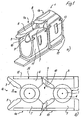
- connection device 1 shows metal parts of a connection device 1 with here two individual terminals 1a and 1b for connecting non-insulated conductor ends of conductors 2, which have one or more conductor core (s) 3 and a conductor insulation 4 surrounding the conductor core (s) 3.
- the individual terminals 1a and 1b each have a cutting and contact spring 5, which consist of two metal legs 6, 7, between which a contact slot 8 is formed and which are either in a plane or slightly angled to each other.
- the legs 6, 7 open like a mouth. Cutting edges 9 in the mouth region 10 allow cutting the conductor insulation 4 when inserting the conductor 2 in the contact slot 8.
- the legs 6, 7 are formed here as the free ends of a common bus bar 12, which extends behind the over-spring 11 in the housing down.
- the two bus bars 12 of the individual terminals 1a, 1b can be placed anywhere, e.g. stapled under the over springs.
- a double connection for two conductors 2 is realized in that two of the connection devices 1a, 1, b are arranged directly one behind the other, in such a way that the slots 8 of the two individual connections 1a and 1b are aligned with one another so that a conductor 2 can be guided through the first individual connection 1a into the second individual connection 1b.
- the free ends of the legs 6, 7 of the rear individual connection 1 b in the direction of conductor insertion X are in their mouth region 10 on the rear ends of the legs 6, 7 of the first or front individual connection 1 a.
- the conductor insulation 4 of a conductor which was first cut through during insertion into the first connection device, further widened and / or severed once again.
- the overlap also precludes the conductor 2 from slipping out of the double connection when passing on the legs 6, 7 of the rear connection device.
- Another advantage of the arrangement with two with respect to the metal parts from each other largely separate individual terminals 1a, 1b is the ability to easily contact conductors 2 different diameters in the two individual terminals 1a, 1b, since each of the two conductors 2 independently of the other conductor. 2 is wired.
- the cutting and contact springs 5 do not overlap, the required installation space length is also particularly significantly reduced again in an advantageous manner.
- Fig. 1 The principle of Fig. 1 can theoretically be extended to three or even more individual connections.
- Fig. 1 and 3a overlap the two cutting and contact springs 5 in the conductor insertion (X) successively arranged individual terminals 1a, 1b so partially that a conductor perpendicular to the conductor insertion direction theoretically also directly from above into the mouth region 10 in the region of the rear cutting - And contact spring 5 is feasible.
- the first cutting and contact springs 5 extend through the rear over-spring 11 of the rear individual connection 1. In this case, it has - in order not to hinder the contacting of the second conductor - in the contact region of the rear in autismeintechnology X cutting and contact device 1 side recesses 19 in the legs 6, 7 of the cutting and contact spring 5.
- a actuator 14 For switching on and off is used according to Fig. 3 (or Fig. 1 and 2) preferably an actuator 14.
- the preferred actuator 14 is formed here as a slide element, which in a corresponding space of an electrical device, in particular a terminal or the like. Slidably is guided.
- It has either an elongated conductor insertion opening (not shown here) designed for receiving two conductors or two conductor insertion openings 15, 16 which are aligned with one another in the conductor insertion direction x.
- It also preferably has on one or both sides of a pin or web 21 which is designed to engage in a corresponding recess of the connecting device receiving insulating housing and which serves to secure the displaceability of the actuating element on the insulating material.
- the conductor insertion openings 15, 16 extend beyond the plane (s) of the cutting and contact springs 5, in whose height the actuating element 14 also has a corresponding slot 17, with which it can be guided via the cutting and contact springs 5.
- the conductor insertion openings 15, 16 can be adapted to the geometry of the metal parts, ie, they can either be spaced such that the individual conductors directly into the mouth areas of two individual terminals - whether they overlap each other slightly more or less (Fig. 2, 3a ) or not (Fig. 3b) - or together in front of the front single connection of two individual terminals 1a, 1b are feasible.
- the individual terminals 1a and 1b or the multiple connection form with the actuating element 14 designed as a double terminal connecting device 1.
- Fig. 4 shows an example in which a longer cutting and contact spring 5 is used, in which two conductors 2 are inserted one behind the other.
- the correspondingly longer over-spring 11 also has additional lateral slots 22 in order to separate as far as possible from each other the spring action of the over-spring on the two conductors 2 in the two areas provided for contacting the conductors 2.
- a longer over-spring 11 with slot and two shorter over springs 11 could be arranged on the cutting and contact spring (not shown here).
- the legs 6, 7 do not necessarily have to run parallel to each other in the region of the slots 8 between them. By appropriate design, however, a tapering in the insertion direction (see FIG. 4c) or u.U. widening wedge are formed, which facilitates the contacting of conductors with different diameters.
- Fig. 5 differs from the previous applications in that the metal parts of two individual terminals 1a, 1b, although aligned with each other but are arranged to each other with a significant height offset. Nevertheless, only one actuating element 14 is provided which, by virtue of its step-like design with two step-like stepped lead-in openings 15, 16, takes this changed arrangement into account. Again, there is the advantage of the possibility of a simple circuit with two conductors with only one movement of a screwdriver or the like. And a compact insertion in the design. The space requirement compared to a design with two actuators is reduced.
- the actuating elements 14 with the conductors 2 can be moved, for example, to lugs or by means supported on abutments in a parent housing tools such as screwdrivers (not shown here).
- FIG. 6 shows metal parts of a further connection device 10 for the insulation-penetrating connection of two conductors 102, which have one or more line conductors 103 and a conductor insulation 104 surrounding the line conductor (s) 103.
- the connecting device has a double cutting and contact spring 107 for connecting two conductors 102, which consists of three parallel to each other and in a plane or substantially in a plane adjacent legs 105, 106, 107.
- a contact slot 108, 109 is respectively formed on both sides of the middle leg 106, ie there is a first contact slot 108 between the left leg 105 and the middle leg 106 in FIG. 6a and a second contact slot 109 between the right leg 107 in FIG. 6a and the middle leg 106.
- the three legs 105, 106, 107 may be formed as free ends of a higher-level busbar 110, which is provided at its free end with the contact slots 108, 109.
- the busbar 110 may be bent in side view L, U (FIG. 6a) or Z-shaped.
- the legs 105, 106, 107 open like a mouth, so that on the one hand a first mouth region 111 in front of the first contact slot 108 and on the other hand, a second mouth region 112 is formed in front of the second contact slot 109.
- the legs 105, 106, 107 are provided with cutting edges 113 for penetrating the conductor insulation.
- the middle leg 106 in this case has at its free end a tapered shape, as it defines in a double function on both sides in each case one of the mouth regions 111, 102 and there severed the conductor insulation.
- the mouth areas can be arranged offset in the conductor insertion direction X, as seen in Figure 6, to each other. It is also conceivable that the conductors 102 in the inserted state are also arranged offset in relation to one another in the double cutting and contact spring 117 in order to further reduce the required installation space width in the connected state (see also FIG. 6b).
- An over-spring 115 which is here U-shaped and whose ends are attached to the outer legs 105, 107 in recesses 114 thereof, increases the contact force on both conductors. 2
- outer legs 105, 107 may also be connected to one another like a pipe-contact, although the arrangement of FIG. 1 with over-spring 115 is preferred.
- actuating element 118 For switching on and switching off Fig. 7 is preferably an actuating element 118.
- the preferred actuating element is designed as a slide element, which is guided in a corresponding free space of an electrical device, in particular a terminal or the like. Slidably. It has either an elongate conductor insertion opening (not shown here) designed for receiving two conductors or two or more conductor insertion openings 119, 120 (corresponding to FIG. 6) arranged laterally next to one another in relation to the conductor insertion direction. Lateral webs 121 serve to guide in a superordinate housing of a connection terminal (not shown here).
- the free space 122 serves to receive the legs 105, 106, 107. The free end of the ladder lays in each case against a lower stop 123.
- the actuating element 118 is preferably one or more preferably open on both sides, so that it builds very narrow.
Landscapes
- Coupling Device And Connection With Printed Circuit (AREA)
- Connections By Means Of Piercing Elements, Nuts, Or Screws (AREA)
- Connections Arranged To Contact A Plurality Of Conductors (AREA)
- Manufacturing Of Electrical Connectors (AREA)
Claims (6)
- Dispositif de raccordement (1) aveca) au moins un raccord multiple ou un contact multiple ou plusieurs raccords ou contacts individuels (1a) et (1 b) pour le raccordement par perforation d'isolant d'extrémités de conducteurs non isolées d'au moins deux conducteurs (2) qui comportent chacun un ou plusieurs fils conducteurs (3) ainsi qu'une isolation de conducteur (4) entourant les fils conducteurs (3),b) chaque raccord multiple ou raccord individuel (1a et 1b) comportant un ressort coupant et de contact (5) qui est constitué de deux branches métalliques (6, 7) entre lesquels est formée une fente de contact (8),c) chacun des conducteurs étant déplaçable à l'aide d'un élément d'actionnement (14) dans la fente de contact (8) et hors de celle-ci,d) l'élément d'actionnement (14) étant réalisé sous forme d'un élément à coulisse,e) les parties métalliques de deux raccords individuels (1a, 1b), c'est-à-dire au moins deux ressorts coupants et de contact (5), étant disposées l'une derrière l'autre en alignement l'une par rapport à l'autre dans le sens d'entrée des conducteurs,f) les ressorts coupants et de contact (5) étant munis chacun d'un sur-ressort (11), etg) le au moins un sur-ressort (11) comportant des évidements (13) et/ou étant configuré avec des fentes latérales,caractérisé en ce que
l'élément d'actionnement (14) comporte au moins deux ouvertures d'entrée de conducteurs (15, 16) en alignement l'une par rapport l'autre dans le sens d'entrée des conducteurs. - Dispositif de raccordement selon l'une quelconque des revendications précédentes, caractérisé en ce que les deux ressorts coupants et de contact (5) des raccords individuels (1a, 1b) disposés l'un derrière l'autre dans le sens d'entrée des conducteurs (X) se chevauchent partiellement.
- Dispositif de raccordement selon l'une quelconque des revendications précédentes, caractérisé en ce que les deux ressorts coupants et de contact (5) des raccords individuels (1a, 1b) disposés l'un derrière l'autre dans le sens d'entrée des conducteurs (X) se chevauchent partiellement de telle manière que les deux conducteurs peuvent être guidés dans le ressort coupant et de contact arrière (5) à travers le ressort coupant et de contact, avant (5).
- Dispositif de raccordement selon l'une quelconque des revendications précédentes, caractérisé en ce que les deux ressorts coupants et de contact (5) des raccords individuels (1a, 1b) disposés l'un derrière l'autre dans le sens d'entrée des conducteurs (X) se chevauchent partiellement de telle manière qu'un conducteur peut être guidé dans la zone d'embouchure (10) du ressort coupant et de contact arrière (5) perpendiculairement au sens d'entrée des conducteurs également directement par le haut.
- Dispositif de raccordement selon l'une quelconque des revendications précédentes, caractérisé en ce que les deux raccords individuels (1a, 1b) sont disposés avec un décalage en hauteur et en ce que les deux ouvertures d'entrée de conducteurs (15, 16) de l'élément d'actionnement (14) présentent un décalage en hauteur correspondant.
- Dispositif de raccordement selon l'une quelconque des revendications précédentes, caractérisé en ce que la fente de contact s'amincit dans le ou à l'inverse du sens d'entrée des conducteurs.
Applications Claiming Priority (4)
| Application Number | Priority Date | Filing Date | Title |
|---|---|---|---|
| DE20308629U | 2003-06-03 | ||
| DE20308630U | 2003-06-03 | ||
| DE20308629U DE20308629U1 (de) | 2003-06-03 | 2003-06-03 | Anschlußvorrichtung zum isolationsdurchdringenden Anschluß von mehreren Leitern |
| DE20308630U DE20308630U1 (de) | 2003-06-03 | 2003-06-03 | Anschlußvorrichtung mit isolationsdurchdringendem Anschluß von wenigsten zwei Leitern |
Publications (3)
| Publication Number | Publication Date |
|---|---|
| EP1484818A2 EP1484818A2 (fr) | 2004-12-08 |
| EP1484818A3 EP1484818A3 (fr) | 2005-01-12 |
| EP1484818B1 true EP1484818B1 (fr) | 2006-12-27 |
Family
ID=33160877
Family Applications (1)
| Application Number | Title | Priority Date | Filing Date |
|---|---|---|---|
| EP04012730A Expired - Lifetime EP1484818B1 (fr) | 2003-06-03 | 2004-05-28 | Dispositif de connexion pour le raccordement par perforation d'isolant d'ou moins deux conducteurs |
Country Status (3)
| Country | Link |
|---|---|
| EP (1) | EP1484818B1 (fr) |
| AT (1) | ATE349783T1 (fr) |
| DE (1) | DE502004002415D1 (fr) |
Families Citing this family (3)
| Publication number | Priority date | Publication date | Assignee | Title |
|---|---|---|---|---|
| DE102008026470A1 (de) * | 2008-06-03 | 2010-02-04 | Bticino S.P.A. | Druckstück für eine Anschlussklemme |
| FR3029698B1 (fr) | 2014-12-05 | 2018-03-02 | Legrand France | Element de connexion electrique a percage de gaine isolante d'un fil electrique |
| FR3113544B1 (fr) | 2020-08-20 | 2022-09-02 | Berker Gmbh & Co Kg | Borne de connexion auto-dénudante d’un conducteur électrique isolé |
Family Cites Families (14)
| Publication number | Priority date | Publication date | Assignee | Title |
|---|---|---|---|---|
| US3897128A (en) * | 1974-03-25 | 1975-07-29 | Amp Inc | Pre-insulated connecting device for a plurality of wires having insulation displacing features |
| US4223971A (en) * | 1979-01-05 | 1980-09-23 | Amp Incorporated | Electrical wiring assembly and method |
| FR2455370A1 (fr) * | 1979-04-26 | 1980-11-21 | Bunker Ramo | Element de contact pour raccordement sans denudage de fils electriques |
| GB2075279B (en) * | 1980-05-02 | 1984-02-08 | Egerton A C Ltd | Terminal connector |
| DE3627333A1 (de) * | 1986-08-12 | 1988-02-18 | Baer Elektrowerke Gmbh & Co Kg | Elektrischer schalter |
| FR2725836A1 (fr) * | 1994-10-17 | 1996-04-19 | Lacroix Jacques | Dispositif de connexion de fils conducteurs gaines |
| DE29603585U1 (de) * | 1996-02-28 | 1997-06-26 | Lumberg Karl Gmbh & Co | Steckverbinder |
| US5860829A (en) * | 1996-05-31 | 1999-01-19 | The Whitaker Corporation | Cross connect terminal block |
| DE19627209C1 (de) * | 1996-07-05 | 1997-10-23 | Siemens Ag | Anschlußvorrichtung für nichtabisolierte Leiter |
| US6074240A (en) * | 1996-10-16 | 2000-06-13 | Marconi Communications Inc. | Terminal block |
| DE19732182C1 (de) * | 1997-07-25 | 1999-03-25 | Quante Ag | Schneidklemm-Kontakt sowie Anschlußleiste oder -modul und Reihenklemme mit einem Schneidklemm-Kontakt |
| EP1020964B1 (fr) * | 1999-01-15 | 2005-10-12 | The Whitaker Corporation | Connecteur pour terminer des câbles de communication |
| US6080006A (en) * | 1999-05-26 | 2000-06-27 | Broder; Eric S. | Insulated connector for electrical conductors |
| ES2231360T3 (es) * | 2000-09-25 | 2005-05-16 | WEIDMULLER INTERFACE GMBH & CO. | Borne de terminal con contactos de corte y dispositivo de conexion. |
-
2004
- 2004-05-28 AT AT04012730T patent/ATE349783T1/de not_active IP Right Cessation
- 2004-05-28 EP EP04012730A patent/EP1484818B1/fr not_active Expired - Lifetime
- 2004-05-28 DE DE502004002415T patent/DE502004002415D1/de not_active Expired - Lifetime
Also Published As
| Publication number | Publication date |
|---|---|
| ATE349783T1 (de) | 2007-01-15 |
| EP1484818A2 (fr) | 2004-12-08 |
| EP1484818A3 (fr) | 2005-01-12 |
| DE502004002415D1 (de) | 2007-02-08 |
Similar Documents
| Publication | Publication Date | Title |
|---|---|---|
| EP3507866B1 (fr) | Borne de raccordement d'un conducteur | |
| EP1253670B1 (fr) | Borne à ressort et barette à bornes | |
| EP1515397B1 (fr) | Borne de connexion électrique à raccordement enfichable directe de conducteur électrique | |
| DE10351289B4 (de) | Steckbrücke für elektrische Anschluß- und/oder Verbindungsklemmen | |
| DE4433983A1 (de) | Anschlußklemme für elektrische Installationen | |
| DE102011056043B4 (de) | Stromschienenabgriffelement | |
| DE20114612U1 (de) | Reihenklemme mit Schneidkontakten und Anschlußvorrichtung | |
| DE4102784C2 (de) | Anschlußklemme | |
| DE102009030645B4 (de) | Brückerelement und Set aus zumindest einem Klemmelement und Brückerelement | |
| DE112008004167B4 (de) | Verbindervorrichtung und Steuerungszentrum mit einer Funktionseinheit mit einer solchen Verbindervorrichtung | |
| DE29719177U1 (de) | Reihenklemmenanordnung | |
| DE10134417C1 (de) | Elektrische Anschluß- oder Verbindungseinrichtung | |
| EP0090317A2 (fr) | Dispositif pour connecter des conducteurs électriques en forme de fil ou de brin | |
| DE20305313U1 (de) | Anschlußeinrichtung | |
| EP1331693B1 (fr) | Plaque à bornes | |
| DE20211513U1 (de) | Anschlußvorrichtung mit Klemmfeder | |
| EP1020954B1 (fr) | Borne de connexion électrique | |
| EP1484818B1 (fr) | Dispositif de connexion pour le raccordement par perforation d'isolant d'ou moins deux conducteurs | |
| EP1432076B1 (fr) | Barette à bornes électrique | |
| WO2003067725A1 (fr) | Dispositif de raccordement ou de distribution pour appareils electriques d'installation | |
| DE10238852B3 (de) | Schaltgerät | |
| EP1587166B1 (fr) | Bloc de répartition | |
| DE19607381C2 (de) | Steckverbinder | |
| EP4109684B1 (fr) | Agencement de contact | |
| DE20308630U1 (de) | Anschlußvorrichtung mit isolationsdurchdringendem Anschluß von wenigsten zwei Leitern |
Legal Events
| Date | Code | Title | Description |
|---|---|---|---|
| PUAI | Public reference made under article 153(3) epc to a published international application that has entered the european phase |
Free format text: ORIGINAL CODE: 0009012 |
|
| PUAL | Search report despatched |
Free format text: ORIGINAL CODE: 0009013 |
|
| AK | Designated contracting states |
Kind code of ref document: A2 Designated state(s): AT BE BG CH CY CZ DE DK EE ES FI FR GB GR HU IE IT LI LU MC NL PL PT RO SE SI SK TR |
|
| AX | Request for extension of the european patent |
Extension state: AL HR LT LV MK |
|
| AK | Designated contracting states |
Kind code of ref document: A3 Designated state(s): AT BE BG CH CY CZ DE DK EE ES FI FR GB GR HU IE IT LI LU MC NL PL PT RO SE SI SK TR |
|
| AX | Request for extension of the european patent |
Extension state: AL HR LT LV MK |
|
| 17P | Request for examination filed |
Effective date: 20050125 |
|
| 17Q | First examination report despatched |
Effective date: 20050329 |
|
| AKX | Designation fees paid |
Designated state(s): AT BE BG CH CY CZ DE DK EE ES FI FR GB GR HU IE IT LI LU MC NL PL PT RO SE SI SK TR |
|
| GRAP | Despatch of communication of intention to grant a patent |
Free format text: ORIGINAL CODE: EPIDOSNIGR1 |
|
| GRAS | Grant fee paid |
Free format text: ORIGINAL CODE: EPIDOSNIGR3 |
|
| GRAA | (expected) grant |
Free format text: ORIGINAL CODE: 0009210 |
|
| AK | Designated contracting states |
Kind code of ref document: B1 Designated state(s): AT BE BG CH CY CZ DE DK EE ES FI FR GB GR HU IE IT LI LU MC NL PL PT RO SE SI SK TR |
|
| PG25 | Lapsed in a contracting state [announced via postgrant information from national office to epo] |
Ref country code: IT Free format text: LAPSE BECAUSE OF FAILURE TO SUBMIT A TRANSLATION OF THE DESCRIPTION OR TO PAY THE FEE WITHIN THE PRESCRIBED TIME-LIMIT;WARNING: LAPSES OF ITALIAN PATENTS WITH EFFECTIVE DATE BEFORE 2007 MAY HAVE OCCURRED AT ANY TIME BEFORE 2007. THE CORRECT EFFECTIVE DATE MAY BE DIFFERENT FROM THE ONE RECORDED. Effective date: 20061227 Ref country code: RO Free format text: LAPSE BECAUSE OF FAILURE TO SUBMIT A TRANSLATION OF THE DESCRIPTION OR TO PAY THE FEE WITHIN THE PRESCRIBED TIME-LIMIT Effective date: 20061227 Ref country code: CZ Free format text: LAPSE BECAUSE OF FAILURE TO SUBMIT A TRANSLATION OF THE DESCRIPTION OR TO PAY THE FEE WITHIN THE PRESCRIBED TIME-LIMIT Effective date: 20061227 Ref country code: DK Free format text: LAPSE BECAUSE OF FAILURE TO SUBMIT A TRANSLATION OF THE DESCRIPTION OR TO PAY THE FEE WITHIN THE PRESCRIBED TIME-LIMIT Effective date: 20061227 Ref country code: SI Free format text: LAPSE BECAUSE OF FAILURE TO SUBMIT A TRANSLATION OF THE DESCRIPTION OR TO PAY THE FEE WITHIN THE PRESCRIBED TIME-LIMIT Effective date: 20061227 Ref country code: NL Free format text: LAPSE BECAUSE OF FAILURE TO SUBMIT A TRANSLATION OF THE DESCRIPTION OR TO PAY THE FEE WITHIN THE PRESCRIBED TIME-LIMIT Effective date: 20061227 Ref country code: SK Free format text: LAPSE BECAUSE OF FAILURE TO SUBMIT A TRANSLATION OF THE DESCRIPTION OR TO PAY THE FEE WITHIN THE PRESCRIBED TIME-LIMIT Effective date: 20061227 Ref country code: IE Free format text: LAPSE BECAUSE OF FAILURE TO SUBMIT A TRANSLATION OF THE DESCRIPTION OR TO PAY THE FEE WITHIN THE PRESCRIBED TIME-LIMIT Effective date: 20061227 Ref country code: FI Free format text: LAPSE BECAUSE OF FAILURE TO SUBMIT A TRANSLATION OF THE DESCRIPTION OR TO PAY THE FEE WITHIN THE PRESCRIBED TIME-LIMIT Effective date: 20061227 Ref country code: PL Free format text: LAPSE BECAUSE OF FAILURE TO SUBMIT A TRANSLATION OF THE DESCRIPTION OR TO PAY THE FEE WITHIN THE PRESCRIBED TIME-LIMIT Effective date: 20061227 |
|
| REG | Reference to a national code |
Ref country code: GB Ref legal event code: FG4D Free format text: NOT ENGLISH |
|
| RIN1 | Information on inventor provided before grant (corrected) |
Inventor name: DIEKMANN, TORSTEN Inventor name: DIEKMANN, JOERG Inventor name: HANNING, WALTER Inventor name: HOEING, MICHAEL |
|
| REG | Reference to a national code |
Ref country code: IE Ref legal event code: FG4D Free format text: LANGUAGE OF EP DOCUMENT: GERMAN |
|
| REF | Corresponds to: |
Ref document number: 502004002415 Country of ref document: DE Date of ref document: 20070208 Kind code of ref document: P |
|
| PG25 | Lapsed in a contracting state [announced via postgrant information from national office to epo] |
Ref country code: BG Free format text: LAPSE BECAUSE OF FAILURE TO SUBMIT A TRANSLATION OF THE DESCRIPTION OR TO PAY THE FEE WITHIN THE PRESCRIBED TIME-LIMIT Effective date: 20070327 Ref country code: SE Free format text: LAPSE BECAUSE OF FAILURE TO SUBMIT A TRANSLATION OF THE DESCRIPTION OR TO PAY THE FEE WITHIN THE PRESCRIBED TIME-LIMIT Effective date: 20070327 |
|
| PG25 | Lapsed in a contracting state [announced via postgrant information from national office to epo] |
Ref country code: ES Free format text: LAPSE BECAUSE OF FAILURE TO SUBMIT A TRANSLATION OF THE DESCRIPTION OR TO PAY THE FEE WITHIN THE PRESCRIBED TIME-LIMIT Effective date: 20070407 |
|
| PG25 | Lapsed in a contracting state [announced via postgrant information from national office to epo] |
Ref country code: PT Free format text: LAPSE BECAUSE OF FAILURE TO SUBMIT A TRANSLATION OF THE DESCRIPTION OR TO PAY THE FEE WITHIN THE PRESCRIBED TIME-LIMIT Effective date: 20070528 |
|
| NLV1 | Nl: lapsed or annulled due to failure to fulfill the requirements of art. 29p and 29m of the patents act | ||
| GBV | Gb: ep patent (uk) treated as always having been void in accordance with gb section 77(7)/1977 [no translation filed] |
Effective date: 20061227 |
|
| EN | Fr: translation not filed | ||
| PLBE | No opposition filed within time limit |
Free format text: ORIGINAL CODE: 0009261 |
|
| STAA | Information on the status of an ep patent application or granted ep patent |
Free format text: STATUS: NO OPPOSITION FILED WITHIN TIME LIMIT |
|
| PG25 | Lapsed in a contracting state [announced via postgrant information from national office to epo] |
Ref country code: GB Free format text: LAPSE BECAUSE OF FAILURE TO SUBMIT A TRANSLATION OF THE DESCRIPTION OR TO PAY THE FEE WITHIN THE PRESCRIBED TIME-LIMIT Effective date: 20061227 |
|
| 26N | No opposition filed |
Effective date: 20070928 |
|
| BERE | Be: lapsed |
Owner name: WEIDMULLER INTERFACE G.M.B.H. & CO. KG Effective date: 20070531 |
|
| PG25 | Lapsed in a contracting state [announced via postgrant information from national office to epo] |
Ref country code: MC Free format text: LAPSE BECAUSE OF NON-PAYMENT OF DUE FEES Effective date: 20070531 |
|
| PG25 | Lapsed in a contracting state [announced via postgrant information from national office to epo] |
Ref country code: BE Free format text: LAPSE BECAUSE OF NON-PAYMENT OF DUE FEES Effective date: 20070531 |
|
| PG25 | Lapsed in a contracting state [announced via postgrant information from national office to epo] |
Ref country code: GR Free format text: LAPSE BECAUSE OF FAILURE TO SUBMIT A TRANSLATION OF THE DESCRIPTION OR TO PAY THE FEE WITHIN THE PRESCRIBED TIME-LIMIT Effective date: 20070328 Ref country code: FR Free format text: LAPSE BECAUSE OF FAILURE TO SUBMIT A TRANSLATION OF THE DESCRIPTION OR TO PAY THE FEE WITHIN THE PRESCRIBED TIME-LIMIT Effective date: 20070817 |
|
| PG25 | Lapsed in a contracting state [announced via postgrant information from national office to epo] |
Ref country code: AT Free format text: LAPSE BECAUSE OF NON-PAYMENT OF DUE FEES Effective date: 20070528 |
|
| PG25 | Lapsed in a contracting state [announced via postgrant information from national office to epo] |
Ref country code: FR Free format text: LAPSE BECAUSE OF FAILURE TO SUBMIT A TRANSLATION OF THE DESCRIPTION OR TO PAY THE FEE WITHIN THE PRESCRIBED TIME-LIMIT Effective date: 20061227 |
|
| REG | Reference to a national code |
Ref country code: CH Ref legal event code: PL |
|
| PG25 | Lapsed in a contracting state [announced via postgrant information from national office to epo] |
Ref country code: LI Free format text: LAPSE BECAUSE OF NON-PAYMENT OF DUE FEES Effective date: 20080531 Ref country code: CH Free format text: LAPSE BECAUSE OF NON-PAYMENT OF DUE FEES Effective date: 20080531 Ref country code: EE Free format text: LAPSE BECAUSE OF FAILURE TO SUBMIT A TRANSLATION OF THE DESCRIPTION OR TO PAY THE FEE WITHIN THE PRESCRIBED TIME-LIMIT Effective date: 20061227 |
|
| PG25 | Lapsed in a contracting state [announced via postgrant information from national office to epo] |
Ref country code: LU Free format text: LAPSE BECAUSE OF NON-PAYMENT OF DUE FEES Effective date: 20070528 Ref country code: CY Free format text: LAPSE BECAUSE OF FAILURE TO SUBMIT A TRANSLATION OF THE DESCRIPTION OR TO PAY THE FEE WITHIN THE PRESCRIBED TIME-LIMIT Effective date: 20061227 |
|
| PG25 | Lapsed in a contracting state [announced via postgrant information from national office to epo] |
Ref country code: TR Free format text: LAPSE BECAUSE OF FAILURE TO SUBMIT A TRANSLATION OF THE DESCRIPTION OR TO PAY THE FEE WITHIN THE PRESCRIBED TIME-LIMIT Effective date: 20061227 Ref country code: HU Free format text: LAPSE BECAUSE OF FAILURE TO SUBMIT A TRANSLATION OF THE DESCRIPTION OR TO PAY THE FEE WITHIN THE PRESCRIBED TIME-LIMIT Effective date: 20070628 |
|
| PGFP | Annual fee paid to national office [announced via postgrant information from national office to epo] |
Ref country code: DE Payment date: 20120523 Year of fee payment: 9 |
|
| PG25 | Lapsed in a contracting state [announced via postgrant information from national office to epo] |
Ref country code: DE Free format text: LAPSE BECAUSE OF NON-PAYMENT OF DUE FEES Effective date: 20131203 |
|
| REG | Reference to a national code |
Ref country code: DE Ref legal event code: R119 Ref document number: 502004002415 Country of ref document: DE Effective date: 20131203 |