EP1486808A2 - Réceptacle pour connexion à fibre optique et sa méthode de fabrication - Google Patents
Réceptacle pour connexion à fibre optique et sa méthode de fabrication Download PDFInfo
- Publication number
- EP1486808A2 EP1486808A2 EP04077203A EP04077203A EP1486808A2 EP 1486808 A2 EP1486808 A2 EP 1486808A2 EP 04077203 A EP04077203 A EP 04077203A EP 04077203 A EP04077203 A EP 04077203A EP 1486808 A2 EP1486808 A2 EP 1486808A2
- Authority
- EP
- European Patent Office
- Prior art keywords
- ferrule
- inner part
- housing
- optical fiber
- optical
- Prior art date
- Legal status (The legal status is an assumption and is not a legal conclusion. Google has not performed a legal analysis and makes no representation as to the accuracy of the status listed.)
- Granted
Links
Images


Classifications
-
- G—PHYSICS
- G02—OPTICS
- G02B—OPTICAL ELEMENTS, SYSTEMS OR APPARATUS
- G02B6/00—Light guides; Structural details of arrangements comprising light guides and other optical elements, e.g. couplings
- G02B6/24—Coupling light guides
- G02B6/36—Mechanical coupling means
- G02B6/38—Mechanical coupling means having fibre to fibre mating means
- G02B6/3807—Dismountable connectors, i.e. comprising plugs
- G02B6/389—Dismountable connectors, i.e. comprising plugs characterised by the method of fastening connecting plugs and sockets, e.g. screw- or nut-lock, snap-in, bayonet type
- G02B6/3893—Push-pull type, e.g. snap-in, push-on
-
- G—PHYSICS
- G02—OPTICS
- G02B—OPTICAL ELEMENTS, SYSTEMS OR APPARATUS
- G02B6/00—Light guides; Structural details of arrangements comprising light guides and other optical elements, e.g. couplings
- G02B6/24—Coupling light guides
- G02B6/36—Mechanical coupling means
- G02B6/38—Mechanical coupling means having fibre to fibre mating means
- G02B6/3807—Dismountable connectors, i.e. comprising plugs
- G02B6/381—Dismountable connectors, i.e. comprising plugs of the ferrule type, e.g. fibre ends embedded in ferrules, connecting a pair of fibres
- G02B6/3825—Dismountable connectors, i.e. comprising plugs of the ferrule type, e.g. fibre ends embedded in ferrules, connecting a pair of fibres with an intermediate part, e.g. adapter, receptacle, linking two plugs
-
- G—PHYSICS
- G02—OPTICS
- G02B—OPTICAL ELEMENTS, SYSTEMS OR APPARATUS
- G02B6/00—Light guides; Structural details of arrangements comprising light guides and other optical elements, e.g. couplings
- G02B6/24—Coupling light guides
- G02B6/36—Mechanical coupling means
- G02B6/38—Mechanical coupling means having fibre to fibre mating means
- G02B6/3807—Dismountable connectors, i.e. comprising plugs
- G02B6/3873—Connectors using guide surfaces for aligning ferrule ends, e.g. tubes, sleeves, V-grooves, rods, pins, balls
- G02B6/3874—Connectors using guide surfaces for aligning ferrule ends, e.g. tubes, sleeves, V-grooves, rods, pins, balls using tubes, sleeves to align ferrules
- G02B6/3877—Split sleeves
-
- G—PHYSICS
- G02—OPTICS
- G02B—OPTICAL ELEMENTS, SYSTEMS OR APPARATUS
- G02B6/00—Light guides; Structural details of arrangements comprising light guides and other optical elements, e.g. couplings
- G02B6/24—Coupling light guides
- G02B6/36—Mechanical coupling means
- G02B6/38—Mechanical coupling means having fibre to fibre mating means
- G02B6/3807—Dismountable connectors, i.e. comprising plugs
- G02B6/3897—Connectors fixed to housings, casing, frames or circuit boards
Definitions
- the present invention relates to an optical receptacle and a method for manufacturing the same. More. particularly, the present invention relates to an optical receptacle which is applied advantageously to connecting parts between a device having incorporated therein an input or output circuit, such as an ONU (optical network unit) module, and an optical fiber connector plug fitted to an outer optical cord as well as to a method for manufacturing the same.
- an input or output circuit such as an ONU (optical network unit) module
- an optical fiber connector plug fitted to an outer optical cord
- Optical connectors which are used for connecting optical fibers include IEC 1754-4 "Type SC Connector Family" prescribed in "JIS C-5973” (1990). This connector is generally called “SC-type optical fiber connector” and used widely in optical transmission systems.
- SC type optical fiber connectors couples detachably optical devices such as photo diodes (hereafter, sometimes referred to as "PD") or laser diodes (hereafter, sometimes referred to as "LD”) with optical fibers.
- Optical receptacles are optical components which connect the optical connectors with optical fiber connector plugs that are fitted on one hand to a device having input and output circuits for optical signals and on the other hand to an optical fiber connector plug.
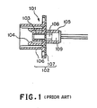
- FIG. 1 shows schematically a conventional "SC-type optical receptacle".
- a conventional optical receptacle 101 has an interface equivalent to an adapter in SC-type optical connectors.
- a housing 102 includes a substrate 107, to which a precision sleeve 103 is fixed, and a hook portion 104 and an outer shell 106. From a terminal end of the housing 102 are inserted a lens 108 and an optical element 109 such as PD or LD.
- the lens 108 and the optical element 109 are arranged coaxially with the center axis of the precision sleeve 103 so that the optical axis of an optical fiber is aligned to that of the element to which the optical fiber is to be connected.
- the precision sleeve 103 not only high precision alignment with the precision sleeve 103, the optical element 109 and so on is required but also the precision sleeve 103 itself must be fabricated with high precision, thus increasing the manufacturing cost of the optical receptacle.
- optical elements can be coupled with satisfactory working efficiency through fibers fitted to the optical elements in advance.
- an optical fiber is to be connected to an optical waveguide instead of an optical element itself, it is difficult to attach an optical receptacle directly to an end surface of the optical waveguide.
- optical connector there can be used widely the above-described SC-type optical fiber connectors.
- Fig. 2 is a partial cross sectional view showing a conventional SC-type optical fiber connector.
- Fig. 3 is an exploded view of a conventional SC-type optical fiber connector adapter and a conventional SC-type optical fiber connector plug, corresponding to the part A shown in Fig. 2.
- input and output portions of an optical module can be fabricated, for example, by attaching, to a tip portion of an optical fiber pigtail, an SC-type optical fiber connector 202 and connecting the SC-type optical fiber connector 208 to an SC-type optical fiber adapter 203 which is fitted to a panel portion of the optical module (not shown).
- the SC-type optical fiber adapter 203 has two housings 204 within each of which a sleeve 205 and hooks 206 are provided. In the sleeve 205 which is fitted in the housing 204 is held a split sleeve 211 as shown in Fig. 3.
- the optical fiber connector 208 includes the coupling device 202 one end of which can be fitted in the SC-type optical fiber adapter 203 and the other end thereof is inserted an outer shell 212.
- a ferrule 209 is pressed into the outer shell by a spring 213 which is supported by an inner shell 214 over which a crimp ring 215 covers.
- the crimp ring 215 together with an intervening ring 216 are contained in a boot 217, which is connected to the tension member and coating of an optical fiber cord 201.
- the outer shell 212, the ferrule 209, the spring 213, the inner shell 214, the crimp ring 215, the ring 216 are coaxially aligned and contained within the inner cavity of the coupling device 202..
- Connection to an optical fiber cable outside the optical module can be achieved by engaging the optical fiber connector plug 208 in the housing 204 such that the ferrule 209 is inserted in a split sleeve 211 and the housing 210 of the plug 208 to is clamped by the hooks 206 so that the plug 208 is prevented from rearward movement and thus does not come out of the housing 204.
- the SC-type optical fiber connector shown in Fig. 2 is of a dual engagement structure. More particularly, the ferrule 209 floats within the cavity of the plug housing 210. The plug housing 210 and the sleeve 205 engage with each other. On the other hand, the ferrule 209 and the split sleeve 211 engage with each other. The sleeve 205 and the split sleeve 211 engage with the respective counterparts independently of each other. Due to this dual engagement, the SC-type optical fiber connector is resistant to tension or bending urged to the optical cord from outside. If such an outer force is applied to the connector, the connector is given substantially no adverse effect on its connecting characteristics. As shown in Fig. 3, the conventional SC-type optical fiber adapter and the SC-type optical fiber connector plug together comprise thirteen (13) components. The SC-type optical fiber connector plug is prescribed
- SC-type optical fiber connectors are used under various conditions.
- the optical cord receives no outer force inside the optical module to which it is connected. Therefore, in such an environment where no outer force is urged, it is wasteful to use the above-described SC-type optical fiber connector.
- the use of SC-type optical fiber connectors is disadvantageous in view of production costs, space required for fitting it.
- An object of the present invention is to solve the above-described problems and provide an optical receptacle which is of a simple structure and less expensive as well as a method for manufacturing such an optical receptacle.
- the present invention provides an optical receptacle which comprises:
- the housing may comprise a fixing mechanism which fixes the inner part in position when the inner part is inlayed in the outer part.
- the housing may comprise a fixing mechanism which fixes the inner part in position when the inner part is inlayed in the outer part from a side where the first ferrule is positioned.
- the first ferrule may comprise a flange having an octagonal prism portion coaxial with the first ferrule and a tetragonal prism portion coaxial with the first ferrule continuing to the octagonal prism portion.
- the octagonal prism portion may engage with the first hook portions.
- the first hook portions may have respective claws; wherein the octagonal prism may have two parallel surfaces arranged along a longitudinal axis of the ferrule at a distance larger than a gap defined between inner surfaces of the claws of the first hook portions; and wherein the tetragonal prism portion may have two parallel surfaces at a distance is smaller than the gap between the inner surfaces of the claws of the first hook portions and a diagonal line of the tetragonal prism portion has a length which is equal to or larger than the distance between the two parallel surfaces of the octagonal prism portion.
- the diagonal line of the octagonal prism portion may have a length such that the first ferrule is allowed to rotate in the inner part of the housing.
- the present invention provides a method for manufacturing an optical receptacle as claimed in claim 1, which comprises the steps of:
- the inner part may be inserted in the outer part until a fixing mechanism provided in the housing fixes the inner part in position in the outer part.
- the present invention provides a housing for an optical receptacle, having a base end adapted for fitting a first ferrule and a nose end adapted for fitting an optical fiber connector plug, the housing comprising:
- the housing may comprise a fixing mechanism which fixes the inner part in position when the inner part is inlayed in the outer part.
- the housing may comprise a fixing mechanism which fixes the inner part in position when the inner part is inlayed in the outer part from a side where the first ferrule is positioned.
- the fixing mechanism may fix the inner part in position when the inner part is inlayed in the outer part from a side where the first ferrule is positioned.
- the present invention provides a method for manufacturing a housing for an optical receptacle as claimed in claim 1, comprising the steps of:
- the inner part may be inserted in the outer part until a fixing mechanism provided in the housing fixes the inner part in position in the outer part.
- the housing inlays the inner and outer parts therein to give a fixed structure so that no additional operation such as ultrasonic welding or the like is needed upon assembling the housing. This simplifies assembling operation greatly.
- the inner part can be inserted into the outer part from the side where a terminal or base end of the first ferrule is positioned in the outer part (cf. Figs. 8A and 8B) and inlayed and fixed in the outer part. As a result, even if undesirable tensile force is urged onto the optical fiber cable to which the first ferrule is attached, the inlayed portion of the inner part will not disengage from and come out of the outer part.
- the first ferrule has a flange of an octagonal prism in shape coaxial with the axis of the first ferrule.
- the octagonal prism continues to a tetragonal prism coaxial with the axis of the first ferrule.
- the first hooks engage with the octagonal prism, two opposite parallel side surfaces of the octagonal prism are spaced apart from each other at a distance which is larger than the gap between the inner surfaces of the claws of the first hooks.
- the two opposite parallel side surfaces of the tetragonal prism are spaced apart from each other at a distance is smaller than the gap between the inner surfaces of the claws of the first hooks.
- the diagonal line has a length equal to or slightly greater than the distance between the parallel side surfaces of the octagonal prism.
- the first ferrule held at the base portion of the housing by the first hooks is fitted in a split sleeve while in the optical fiber connector plug connected to the housing at its nose end, the second ferrule is fitted in the split sleeve so that it is aligned and held at the position of fitting by the second hooks.
- the first hooks for engaging with the first ferrule and the second hooks for engaging with the optical fiber connector plug are molded integrally (i.e., solidly or as one-piece) as an inner part so that the relationship between the positions of the first and second ferrules at the time of coupling can readily be maintained with high precision without high precision assembling operations.
- a spring which has been conventionally required to press the first ferrule may be eliminated. Without springs, the first and second ferrules to be connected can firmly be pressed against each other so that the reliability in connecting characteristics can be increased.
- the split sleeve can reach to the foot of the flange of the first ferrule so that a shorter ferrule can be used, with the result that when ferrules are manufactured less grinding of the outer surfaces of the ferrule is required. Therefore, the optical receptacle can be manufactured at low cost.
- the split sleeve is drawn out simultaneously so that less friction occurs between the first ferrule and the split sleeve. Therefore, inexpensive materials with low friction resistance,such as glass and plastics can be put in practical use for the ferrule.
- optical receptacle is designed to connect optical transmission components and for this purpose is attached to one of the components.
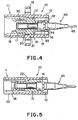
- an optical receptacle 10 includes a housing 11, a split sleeve 30 and a ferrule 40 to one end of which the split sleeve 30 is connected.
- the housing 11 is capable of containing the split sleeve 30 and a part of the ferrule 40.
- the housing 11 is in form and includes an outer part 12 and an inner part 13 which is inserted into the outer part 12. At a terminal of the inner part 13 is provided a fitting portion 14 on whose inner surface a flange 42 of the first ferrule 40 fitted (Fig. 5). Above and below the fitting part 14 are arranged a pair of first hooks 15 having respective first claws 16 on the tips thereof. The first hooks 15 with the first claws 16 hold the flange 42 of the first ferrule 40 in position (Fig. 4).
- a key way 23 for holding the optical fiber connector 51 having a key 54 and receives the key 54 (Figs. 5 and 6).
- a fitting flange 19 formed of fitting holes 24 through which screws or the like fitting means are inserted to fix the housing to an optical module (not shown) in position (Figs. 4 and 6).
- split sleeve 30 On the inner surface of the inner part 13 a split sleeve 30 is fitted. In the split sleeve 30 are fitted on one hand the first ferrule 41 which is fitted from the side of the bottom end of the inner part 13, or from right to left in Fig. 4, and on the other hand the second ferrule 52 of the optical fiber connector plug 51 to be connected (Fig. 12). Thus, the split sleeve 30 allow the first and second ferrules 40 and 52 to align in the axial direction (Fig. 12).
- the housing 11 is constructed.
- the inner part 13 has first protrusions 20 on its upper and lower surfaces while the outer part 12 has on its inner surface a second protrusion 21 and a step 22.
- the inner part 13 is inserted into the outer part 12 from the side of the base end of the housing 11 until the first protrusions 20 pass by the second protrusion 21 against an inward force urged to the inner part 13 by a slightly constricted inner diameter of the cavity. As soon as the first protrusions pass by the second protrusion 21, a portion of the inner part 13 abuts the step 22 provided on the inner surface of the outer part 12 and thus is fixed.
- the inner part 13 and the outer part 12 contact each other along a sufficient are so that the inner part 13 will not come out of the outer part 12 if an excess or otherwise intolerable external force such as a tensile force is urged to the inner part 13. Therefore, there is no danger that the optical fiber connector plug 51 together with the inner part 13 and the first ferrule 40 is drawn out of the optical module to thereby break the device.
- the first hooks 15 and second hooks 17 are molded integrally as the inner part 13. This construction is advantageous in that the relative positions of the first and second hooks can be set with higher precision and assembling operation is more simple as compared with the conventional method in which the both first and second hooks are fabricated separately and subsequently assembled as by ultrasonic welding.
- the flange 42 of the first ferrule 40 is configured to a shape of a combination of an octagonal prism 43 coaxially connected to a tetragonal prism 44.
- the distance between two opposing parallel surfaces of the tetragonal prism 44 is made smaller than the distance between the second claws 16 themselves.
- the diagonal line of the tetragonal prism 44 has a length of L 1 while the distance between the parallel two surfaces of the octagonal prism is L 2 .
- the length, L 1 , of the diagonal line of the tetragonal prism 44 is the same as or slightly larger than the distance, L 2 , the opposite end points 45 and 46 of the diagonal line contact the inner surface of the first claws 16 when the ferrule 40 is rotated about its longitudinal axis at angles of 45° so that the distance between the opposing first claws 16 is made greater than the two parallel surfaces of the octagonal prism.
- the first ferrule 40 is released and can be readily put out of the inner part 13 of the optical receptacle 10.
- the first ferrule 40 is rotated under the conditions that the second ferrule 52 still contacts on its end surface the end surface of the first ferrule 40, the end surface of the optical fiber in the ferrule tends to be damaged. Accordingly, when the second ferrule 52 is to be taken out of the inner part 13, care must be taken to check to see if the optical fiber connector plug is disconnected from the optical receptacle of the present invention.
- Connection of optical transmission components to each other through the optical receptacle 10 according to the first embodiment of the present invention can be achieved by inserting the optical fiber connector plug 51 into the optical receptacle 10 from its left hand side as seen in Fig. 12 so. that the optical fiber 45 fitted to the first ferrule 40 and the optical fiber cable 53 fitted to the second ferrule 52 are aligned.
- This embodiment is the second embodiment of the optical receptacle of the present invention.
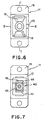
- Fig. 14 is an right end view showing an optical receptacle according to the second embodiment of the present invention.
- Fig. 15 is the first ferrule according to the first embodiment of the present invention.
- Fig. 16 is a right end view showing the first ferrule shown in Fig. 15.
- the optical receptacle according to this embodiment differ from that of the first embodiment of the present invention in the configuration of the flange.
- the first ferrule 40 in the present embodiment has a flange 43a which engages with the first claws 16 and is of a tetragonal prism instead of the octagonal prism that is used in the first ferrule according to the first embodiment of the present invention as shown in Fig. 9.
- the ferrule according to this embodiment of the present invention cannot rotate unlike the first ferrule according to the first embodiment of the present invention described above and, hence, the first ferrule with the tetragonal flange 43a cannot be taken out of the housing 11 by a mere operation, such as rotation about its longitudinal axis, of the first ferrule 40 itself.
- the flange 43a must be disengaged from the first claws 16 of the first hooks 15. This can be achieved by broadening the gap between the first claws 16 by a suitable means.
- a jig in the form of a plate for example can be inserted in the gap between one of the claws 16 and the tetragonal prism 44.
- the jig may be of any desired shape as far as it has two plate-like members such as the plates described above.
- commonly available tools such as tweezers may also be used for the disengagement of the ferrule from the inner part 13 of the optical receptacle according to this embodiment of the present invention.
- the first ferrule 40 never rotates around its longitudinal axis so that no erroneous or harmful operation can occur such that the end face of the optical fiber is damaged by rotation of the first ferrule 40 which contacts the end face of the optical fiber.
- FIG. 17 is a schematic perspective view showing an eight-component-array optical receptacle comprising eight receptacles according to the first embodiment of the present invention integrally assembled side by side.
- the configurations of the first and second ferrules are the same as those of the first and second ferrules in the optical receptacle according to the first or second embodiment of the present invention.
- the array housing 70 is an integrally molded article comprising eight single housings integrally combined arranged in parallel side by side.
- the inner part 13 may be the same as that used in the optical receptacle 10 according to the first embodiment of the present invention. Accordingly, it is sufficient to change the configuration of only the outer part that is simple in structure and inexpensive. Therefore, the optical receptacle according to this embodiment can be realized at low costs as compared with the case where the entire structure has to be newly produced.
- eight-component-array optical receptacle may be realized as a compact article using as an optical fiber connector plug to be connected a high density type SC connector plug 208a having a structure in which the plug is removed with a jig or removing tool after the coupling device is detached from the SC-type optical fiber connector plug.
- This embodiment relates to the manufacture of the housing of the optical receptacle according to any one of EMBODIMENT 1 TO 3 above.
- Fig. 18 is a cross sectional view showing inner and outer parts of an optical receptacle to be assembled, illustrating the step of manufacturing the housing of an optical receptacle according to any one of the foregoing embodiments of the present invention.
- the outer part 12 and the inner part 13 which are components of the housing 11 are separately prepared as integral molded articles, respectively.
- the inner part 13 is inserted in the outer part 12 until the protrusions 21 provided in the inner surface of the outer part 12 engage with the protrusions 20 of the inner part 13 so that the inner part 13 is held fixedly in the outer part 12.
- the housing thus formed requires no further operation such as ultrasonic welding for bonding these components before it is assembled with the same first ferrule used in the optical receptacle according to any one of the foregoing embodiments.
Landscapes
- Physics & Mathematics (AREA)
- General Physics & Mathematics (AREA)
- Optics & Photonics (AREA)
- Mechanical Coupling Of Light Guides (AREA)
- Optical Couplings Of Light Guides (AREA)
Applications Claiming Priority (3)
| Application Number | Priority Date | Filing Date | Title |
|---|---|---|---|
| JP4806195 | 1995-03-08 | ||
| JP04806195A JP3212063B2 (ja) | 1995-03-08 | 1995-03-08 | 光レセプタクル |
| EP96200612A EP0731369B1 (fr) | 1995-03-08 | 1996-03-06 | Réceptacle pour connexion à fibre optique et sa méthode de fabrication |
Related Parent Applications (2)
| Application Number | Title | Priority Date | Filing Date |
|---|---|---|---|
| EP96200612A Division EP0731369B1 (fr) | 1995-03-08 | 1996-03-06 | Réceptacle pour connexion à fibre optique et sa méthode de fabrication |
| EP96200612.8 Division | 1996-03-06 |
Publications (3)
| Publication Number | Publication Date |
|---|---|
| EP1486808A2 true EP1486808A2 (fr) | 2004-12-15 |
| EP1486808A3 EP1486808A3 (fr) | 2004-12-29 |
| EP1486808B1 EP1486808B1 (fr) | 2012-01-25 |
Family
ID=12792841
Family Applications (2)
| Application Number | Title | Priority Date | Filing Date |
|---|---|---|---|
| EP96200612A Expired - Lifetime EP0731369B1 (fr) | 1995-03-08 | 1996-03-06 | Réceptacle pour connexion à fibre optique et sa méthode de fabrication |
| EP04077203A Expired - Lifetime EP1486808B1 (fr) | 1995-03-08 | 1996-03-06 | Réceptacle pour connexion à fibre optique et sa méthode de fabrication |
Family Applications Before (1)
| Application Number | Title | Priority Date | Filing Date |
|---|---|---|---|
| EP96200612A Expired - Lifetime EP0731369B1 (fr) | 1995-03-08 | 1996-03-06 | Réceptacle pour connexion à fibre optique et sa méthode de fabrication |
Country Status (3)
| Country | Link |
|---|---|
| US (2) | US5774611A (fr) |
| EP (2) | EP0731369B1 (fr) |
| JP (1) | JP3212063B2 (fr) |
Cited By (8)
| Publication number | Priority date | Publication date | Assignee | Title |
|---|---|---|---|---|
| WO2006022840A1 (fr) | 2004-08-24 | 2006-03-02 | Corning Cable Systems Llc | Ensemble prise et fiche de fibre optique avec caractéristiques d’alignement et de clavetage |
| WO2008116164A3 (fr) * | 2007-03-22 | 2009-04-09 | Edwards Lifesciences Corp | Connecteur de fibre optique, auto-alignant, à verrouillage amovible |
| WO2010025180A1 (fr) * | 2008-08-27 | 2010-03-04 | Adc Telecommunications, Inc. | Adaptateur pour fibre optique ayant une structure d'alignement de virole moulée en une seule pièce |
| CN102789029A (zh) * | 2011-05-18 | 2012-11-21 | 深圳市博特光通讯设备有限公司 | 一种m型塑料光纤固定装置及固定方法 |
| US8317408B2 (en) | 2009-10-05 | 2012-11-27 | Suncall Corporation | Optical-fiber connection unit, and optical connector and optical adapter used therein |
| US9880357B2 (en) | 2013-03-01 | 2018-01-30 | Harting Electric Gmbh & Co. Kg | Optical module for industrial plug-in connectors of modular design |
| US9915793B2 (en) | 2012-09-21 | 2018-03-13 | Commscope Technologies Llc | Removal tool for a fiber optic ferrule alignment sleeve |
| US10302874B2 (en) | 2015-05-15 | 2019-05-28 | Commscope Telecommunications (Shanghai) Co., Ltd. | Alignment sleeve assembly and fiber optic adapter |
Families Citing this family (126)
| Publication number | Priority date | Publication date | Assignee | Title |
|---|---|---|---|---|
| JP3212063B2 (ja) * | 1995-03-08 | 2001-09-25 | 日本電信電話株式会社 | 光レセプタクル |
| US5815618A (en) * | 1996-06-07 | 1998-09-29 | Molex Incorporated | Adaptor for interconnecting optical fibers |
| JP3066739B2 (ja) | 1996-07-15 | 2000-07-17 | セイコーインスツルメンツ株式会社 | 汎用光コネクタ及びベーシックプラグ |
| JP3535952B2 (ja) * | 1997-05-08 | 2004-06-07 | 古河電気工業株式会社 | バックパネルコネクタ |
| JP3934234B2 (ja) * | 1998-01-21 | 2007-06-20 | 富士通株式会社 | レセプタクルモジュール |
| US6435730B1 (en) * | 1998-05-06 | 2002-08-20 | The Whitaker Corporation | Optical fiber connector with improved ferrule float feature |
| US6812718B1 (en) | 1999-05-27 | 2004-11-02 | Nanonexus, Inc. | Massively parallel interface for electronic circuits |
| US7382142B2 (en) | 2000-05-23 | 2008-06-03 | Nanonexus, Inc. | High density interconnect system having rapid fabrication cycle |
| US6791171B2 (en) | 2000-06-20 | 2004-09-14 | Nanonexus, Inc. | Systems for testing and packaging integrated circuits |
| US7349223B2 (en) | 2000-05-23 | 2008-03-25 | Nanonexus, Inc. | Enhanced compliant probe card systems having improved planarity |
| US7247035B2 (en) | 2000-06-20 | 2007-07-24 | Nanonexus, Inc. | Enhanced stress metal spring contactor |
| US6799976B1 (en) | 1999-07-28 | 2004-10-05 | Nanonexus, Inc. | Construction structures and manufacturing processes for integrated circuit wafer probe card assemblies |
| US6367984B1 (en) * | 1999-11-10 | 2002-04-09 | Lucent Technologies, Inc. | Optical fiber adapter |
| US7579848B2 (en) | 2000-05-23 | 2009-08-25 | Nanonexus, Inc. | High density interconnect system for IC packages and interconnect assemblies |
| US7952373B2 (en) * | 2000-05-23 | 2011-05-31 | Verigy (Singapore) Pte. Ltd. | Construction structures and manufacturing processes for integrated circuit wafer probe card assemblies |
| US9625649B2 (en) * | 2000-07-17 | 2017-04-18 | Commscope Technologies Llc | Connector system with physical security feature |
| US8807843B2 (en) * | 2000-07-17 | 2014-08-19 | Tyco Electronics Corporation | Connector system with physical security feature |
| JP3786581B2 (ja) * | 2001-03-02 | 2006-06-14 | ヒロセ電機株式会社 | 光コネクタ部品 |
| US6609837B2 (en) * | 2001-04-27 | 2003-08-26 | Fitel Usa Corp. | Optical fiber adapter for dissimilar size ferrules |
| US6485189B1 (en) * | 2001-05-09 | 2002-11-26 | Stratos Lightwave, Inc. | High density multiple fiber optic connector |
| US6579014B2 (en) * | 2001-09-28 | 2003-06-17 | Corning Cable Systems Llc | Fiber optic receptacle |
| US6682228B2 (en) | 2002-02-19 | 2004-01-27 | Emcore Corporation | Connector housing for fiber-optic module |
| US6863446B2 (en) | 2002-03-05 | 2005-03-08 | Fci Americas Technology, Inc. | Optical connector adapter with latch inserts |
| AUPS120702A0 (en) | 2002-03-18 | 2002-04-18 | Kingfisher International Pty. Ltd. | An optical fibre connector system |
| DE10219935A1 (de) | 2002-05-03 | 2003-11-27 | Krone Gmbh | Vorrichtung für eine Glasfaserverbindung |
| US6702477B1 (en) * | 2002-09-23 | 2004-03-09 | Fci Americas Technology, Inc. | Adapter with cap for fiber optic connector |
| US6785460B2 (en) * | 2002-11-27 | 2004-08-31 | Corning Cable Systems Llc | Tool to remove a ferrule from a receptacle |
| GB2397895B (en) * | 2003-01-29 | 2006-05-03 | Agilent Technologies Inc | Opticle fibre connector |
| US6866425B2 (en) * | 2003-02-14 | 2005-03-15 | Adc Telecommunications, Inc. | In-line optical device with removable housing and method |
| US6962445B2 (en) | 2003-09-08 | 2005-11-08 | Adc Telecommunications, Inc. | Ruggedized fiber optic connection |
| DE102004013905B4 (de) | 2004-03-17 | 2006-01-26 | Adc Gmbh | Glasfaser-Steckverbindung |
| DE202004020043U1 (de) * | 2004-12-22 | 2006-02-09 | CCS Technology, Inc., Wilmington | Lichtwellenleiteranschlusseinrichtung, Stecker und Steckverbindung für Lichtwellenleiter |
| US7416349B2 (en) * | 2005-07-27 | 2008-08-26 | Adc Telecommunications, Inc. | Fiber optic adapter module |
| US7461980B2 (en) * | 2005-09-13 | 2008-12-09 | Avago Technologies Fiber Ip (Singapore) Pte. Ltd. | Transmitter optical sub-assembly receptacle with thicker split sleeve |
| US7568844B2 (en) * | 2006-08-15 | 2009-08-04 | Corning Cable Systems Llc | Ruggedized fiber optic connector assembly |
| US7985027B2 (en) * | 2006-11-14 | 2011-07-26 | Corning Cable Systems Llc | Adapter assembly for coupling dissimilar fiber optic connectors |
| US7572065B2 (en) * | 2007-01-24 | 2009-08-11 | Adc Telecommunications, Inc. | Hardened fiber optic connector |
| US7614797B2 (en) * | 2007-01-24 | 2009-11-10 | Adc Telecommunications, Inc. | Fiber optic connector mechanical interface converter |
| US7591595B2 (en) | 2007-01-24 | 2009-09-22 | Adc Telelcommunications, Inc. | Hardened fiber optic adapter |
| US7785016B2 (en) | 2007-03-12 | 2010-08-31 | Corning Cable Systems Llc | Fiber optic adapter and connector assemblies |
| WO2008137893A1 (fr) * | 2007-05-06 | 2008-11-13 | Adc Telecommunications, Inc. | Convertisseur d'interface pour des connecteurs de fibres optiques sc |
| WO2008137897A1 (fr) * | 2007-05-06 | 2008-11-13 | Adc Telecommunications, Inc. | Convertisseur servant d'interface mécanique destiné à fabriquer des connecteurs de fibres optiques qui ne sont pas tout-terrain compatibles avec un adaptateur pour fibre optique tout-terrain |
| US7686519B2 (en) * | 2007-06-18 | 2010-03-30 | Adc Telecommunications, Inc. | Hardened fiber optic housing and cable assembly |
| US7744286B2 (en) * | 2007-12-11 | 2010-06-29 | Adc Telecommunications, Inc. | Hardened fiber optic connection system with multiple configurations |
| JP2009170108A (ja) * | 2008-01-10 | 2009-07-30 | Tokai Rika Co Ltd | ダミーコネクタ |
| KR100850925B1 (ko) * | 2008-03-14 | 2008-08-07 | 장종호 | 광섬유 일체형 광어탭터 |
| US7787740B2 (en) * | 2008-06-12 | 2010-08-31 | Corning Cable Systems Llc | Universal cable bracket |
| US8452148B2 (en) | 2008-08-29 | 2013-05-28 | Corning Cable Systems Llc | Independently translatable modules and fiber optic equipment trays in fiber optic equipment |
| US11294136B2 (en) | 2008-08-29 | 2022-04-05 | Corning Optical Communications LLC | High density and bandwidth fiber optic apparatuses and related equipment and methods |
| US8285096B2 (en) | 2008-09-30 | 2012-10-09 | Corning Cable Systems Llc | Fiber optic cable assemblies and securing methods |
| US8272792B2 (en) * | 2008-09-30 | 2012-09-25 | Corning Cable Systems Llc | Retention bodies for fiber optic cable assemblies |
| US8303193B2 (en) * | 2008-09-30 | 2012-11-06 | Corning Cable Systems Llc | Retention bodies for fiber optic cable assemblies |
| WO2010059623A1 (fr) | 2008-11-21 | 2010-05-27 | Adc Telecommunications, Inc. | Module de télécommunications à fibre optique |
| EP2221932B1 (fr) | 2009-02-24 | 2011-11-16 | CCS Technology Inc. | Dispositif de maintien pour câble ou ensemble à utiliser avec un câble |
| US8699838B2 (en) | 2009-05-14 | 2014-04-15 | Ccs Technology, Inc. | Fiber optic furcation module |
| JP4863319B2 (ja) | 2009-05-19 | 2012-01-25 | 日本航空電子工業株式会社 | 光コネクタ |
| US9075216B2 (en) | 2009-05-21 | 2015-07-07 | Corning Cable Systems Llc | Fiber optic housings configured to accommodate fiber optic modules/cassettes and fiber optic panels, and related components and methods |
| US8538226B2 (en) | 2009-05-21 | 2013-09-17 | Corning Cable Systems Llc | Fiber optic equipment guides and rails configured with stopping position(s), and related equipment and methods |
| JP2012530943A (ja) | 2009-06-19 | 2012-12-06 | コーニング ケーブル システムズ リミテッド ライアビリティ カンパニー | 高い光ファイバケーブル実装密度の装置 |
| DE20160489T1 (de) | 2009-06-19 | 2024-06-20 | Corning Optical Communications LLC | Glasfaservorrichtungen mit hoher dichte und bandbreite und zugehörige ausrüstung und verfahren |
| US8712206B2 (en) | 2009-06-19 | 2014-04-29 | Corning Cable Systems Llc | High-density fiber optic modules and module housings and related equipment |
| US8625950B2 (en) | 2009-12-18 | 2014-01-07 | Corning Cable Systems Llc | Rotary locking apparatus for fiber optic equipment trays and related methods |
| JP4925372B2 (ja) * | 2009-12-28 | 2012-04-25 | 日本航空電子工業株式会社 | 光コネクタアダプタ |
| JP5411006B2 (ja) * | 2010-01-21 | 2014-02-12 | 三和電気工業株式会社 | 光コネクタ用簡易プラグ |
| US8992099B2 (en) | 2010-02-04 | 2015-03-31 | Corning Cable Systems Llc | Optical interface cards, assemblies, and related methods, suited for installation and use in antenna system equipment |
| CN102870021B (zh) | 2010-03-02 | 2015-03-11 | 蒂安电子服务有限责任公司 | 光纤通信模块 |
| US8913866B2 (en) | 2010-03-26 | 2014-12-16 | Corning Cable Systems Llc | Movable adapter panel |
| WO2011159387A1 (fr) | 2010-04-16 | 2011-12-22 | Ccs Technology, Inc. | Dispositif d'étanchéité et de serrage pour câbles de données |
| EP2381284B1 (fr) | 2010-04-23 | 2014-12-31 | CCS Technology Inc. | Dispositif de distribution à fibre optique encastré dans le sol |
| US9720195B2 (en) | 2010-04-30 | 2017-08-01 | Corning Optical Communications LLC | Apparatuses and related components and methods for attachment and release of fiber optic housings to and from an equipment rack |
| US9075217B2 (en) | 2010-04-30 | 2015-07-07 | Corning Cable Systems Llc | Apparatuses and related components and methods for expanding capacity of fiber optic housings |
| US8879881B2 (en) | 2010-04-30 | 2014-11-04 | Corning Cable Systems Llc | Rotatable routing guide and assembly |
| US9632270B2 (en) | 2010-04-30 | 2017-04-25 | Corning Optical Communications LLC | Fiber optic housings configured for tool-less assembly, and related components and methods |
| US9519118B2 (en) | 2010-04-30 | 2016-12-13 | Corning Optical Communications LLC | Removable fiber management sections for fiber optic housings, and related components and methods |
| US8660397B2 (en) | 2010-04-30 | 2014-02-25 | Corning Cable Systems Llc | Multi-layer module |
| US8705926B2 (en) | 2010-04-30 | 2014-04-22 | Corning Optical Communications LLC | Fiber optic housings having a removable top, and related components and methods |
| WO2011163266A2 (fr) * | 2010-06-21 | 2011-12-29 | Finisar Corporation | Connecteurs de fibres optiques |
| US8718436B2 (en) | 2010-08-30 | 2014-05-06 | Corning Cable Systems Llc | Methods, apparatuses for providing secure fiber optic connections |
| US9279951B2 (en) | 2010-10-27 | 2016-03-08 | Corning Cable Systems Llc | Fiber optic module for limited space applications having a partially sealed module sub-assembly |
| US8662760B2 (en) | 2010-10-29 | 2014-03-04 | Corning Cable Systems Llc | Fiber optic connector employing optical fiber guide member |
| AU2011336747A1 (en) | 2010-11-30 | 2013-06-20 | Corning Cable Systems Llc | Fiber device holder and strain relief device |
| CN102565957B (zh) * | 2010-12-31 | 2014-03-26 | 深圳日海通讯技术股份有限公司 | 一种光纤连接器 |
| CN103403594B (zh) | 2011-02-02 | 2016-11-23 | 康宁光缆系统有限责任公司 | 适用于为设备机架中的光学底板建立光学连接的稠密的光阀遮蔽的光纤连接器及总成 |
| US9008485B2 (en) | 2011-05-09 | 2015-04-14 | Corning Cable Systems Llc | Attachment mechanisms employed to attach a rear housing section to a fiber optic housing, and related assemblies and methods |
| JP5627009B2 (ja) * | 2011-06-13 | 2014-11-19 | 日本電信電話株式会社 | プラグ及びアダプタを備えた光コネクタ並びに光コネクタの接続方法 |
| CN103649805B (zh) | 2011-06-30 | 2017-03-15 | 康宁光电通信有限责任公司 | 使用非u宽度大小的外壳的光纤设备总成以及相关方法 |
| US8953924B2 (en) | 2011-09-02 | 2015-02-10 | Corning Cable Systems Llc | Removable strain relief brackets for securing fiber optic cables and/or optical fibers to fiber optic equipment, and related assemblies and methods |
| US9417418B2 (en) | 2011-09-12 | 2016-08-16 | Commscope Technologies Llc | Flexible lensed optical interconnect device for signal distribution |
| CN108594384B (zh) | 2011-10-07 | 2022-03-08 | Adc电信公司 | 光纤盒、系统和方法 |
| US9038832B2 (en) | 2011-11-30 | 2015-05-26 | Corning Cable Systems Llc | Adapter panel support assembly |
| CN104272153A (zh) | 2012-03-01 | 2015-01-07 | 蒂科电子公司 | 用于mpo系统的键控 |
| US9250409B2 (en) | 2012-07-02 | 2016-02-02 | Corning Cable Systems Llc | Fiber-optic-module trays and drawers for fiber-optic equipment |
| US9081152B2 (en) | 2012-08-30 | 2015-07-14 | Adc Telecommunications, Inc. | Adapter pack with removable sleeves |
| US9042702B2 (en) | 2012-09-18 | 2015-05-26 | Corning Cable Systems Llc | Platforms and systems for fiber optic cable attachment |
| US9146374B2 (en) | 2012-09-28 | 2015-09-29 | Adc Telecommunications, Inc. | Rapid deployment packaging for optical fiber |
| IN2015DN02869A (fr) | 2012-09-28 | 2015-09-11 | Tyco Electronics Ltd Uk | |
| US9223094B2 (en) | 2012-10-05 | 2015-12-29 | Tyco Electronics Nederland Bv | Flexible optical circuit, cassettes, and methods |
| ES2551077T3 (es) | 2012-10-26 | 2015-11-16 | Ccs Technology, Inc. | Unidad de gestión de fibra óptica y dispositivo de distribución de fibra óptica |
| US9268100B2 (en) * | 2012-11-12 | 2016-02-23 | Commscope, Inc. Of North Carolina | Fiber optic connector adapter |
| US9069141B2 (en) * | 2012-12-10 | 2015-06-30 | Baker Hughes Incorporated | Fiber optic termination arrangement and method of making the same |
| US8985862B2 (en) | 2013-02-28 | 2015-03-24 | Corning Cable Systems Llc | High-density multi-fiber adapter housings |
| US9435975B2 (en) | 2013-03-15 | 2016-09-06 | Commscope Technologies Llc | Modular high density telecommunications frame and chassis system |
| US10444443B2 (en) | 2013-06-27 | 2019-10-15 | CommScope Connectivity Belgium BVBA | Fiber optic cable anchoring device for use with fiber optic connectors and methods of using the same |
| CN104777560B (zh) * | 2014-01-14 | 2017-09-26 | 华为技术有限公司 | 光纤连接器及光纤连接器组件系统 |
| EP3100090A4 (fr) | 2014-01-28 | 2017-09-06 | ADC Telecommunications Inc. | Module de connexion de fibres optiques coulissant avec gestion de mou de câble |
| US9494758B2 (en) | 2014-04-03 | 2016-11-15 | Commscope Technologies Llc | Fiber optic distribution system |
| US9551598B2 (en) | 2014-05-12 | 2017-01-24 | Siemens Energy, Inc. | Fiber optic sensing apparatus with an improved fiber-affixing device |
| JP6318008B2 (ja) * | 2014-05-30 | 2018-04-25 | 株式会社フジクラ | 光コネクタ |
| FR3024244B1 (fr) * | 2014-07-25 | 2018-01-05 | Bbright | Module de couplage du matrice de diodes lasers |
| JP2016109816A (ja) * | 2014-12-04 | 2016-06-20 | 株式会社フジクラ | 光コネクタ用固定部材、光コネクタ及び光コネクタ装置 |
| CN205374820U (zh) * | 2016-02-01 | 2016-07-06 | 上海光联通讯技术有限公司 | 光纤适配器 |
| US10725248B2 (en) | 2017-01-30 | 2020-07-28 | Senko Advanced Components, Inc. | Fiber optic receptacle with integrated device therein incorporating a behind-the-wall fiber optic receptacle |
| US10871619B2 (en) * | 2017-01-30 | 2020-12-22 | Senko Advanced Components, Inc. | Cassette assembly for a plural of fiber optic receptacles |
| CN206479676U (zh) * | 2017-02-16 | 2017-09-08 | 光联通讯有限公司 | 光纤插座、光纤连接装置及光纤插座模块 |
| JP7115739B2 (ja) * | 2017-08-09 | 2022-08-09 | 株式会社精工技研 | 光コネクタアダプタ |
| EP3692404A4 (fr) | 2017-10-02 | 2021-06-16 | Commscope Technologies LLC | Circuit optique et procédé de préparation |
| JP7079924B2 (ja) * | 2017-10-30 | 2022-06-03 | アダマンド並木精密宝石株式会社 | 光レセプタクル |
| TW201928429A (zh) * | 2017-12-27 | 2019-07-16 | 和碩聯合科技股份有限公司 | 光纖連接器 |
| WO2020146500A1 (fr) | 2019-01-09 | 2020-07-16 | Commscope Technologies Llc | Adaptateur de fibre optique à structures moulées d'un seul tenant |
| CN114600018B (zh) * | 2019-07-23 | 2024-04-09 | 扇港元器件有限公司 | 用于接收与插芯组件相对的光纤连接器的超小型插座 |
| CN110927892B (zh) * | 2019-12-19 | 2021-12-07 | 武汉邮埃服光电科技有限公司 | 一种光纤连接器组件 |
| TWI781413B (zh) * | 2020-02-26 | 2022-10-21 | 立佳興業股份有限公司 | 卡扣結構及其光學連接器插座 |
| TWI722902B (zh) * | 2020-02-26 | 2021-03-21 | 立佳興業股份有限公司 | 卡扣結構及其光學連接器插座 |
| US12339511B2 (en) | 2020-03-31 | 2025-06-24 | Commscope Technologies Llc | Fiber optic cable management systems and methods |
| WO2022059645A1 (fr) | 2020-09-16 | 2022-03-24 | 住友電気工業株式会社 | Câblage optique et procédé de connexion optique |
| CN113625397B (zh) * | 2021-06-29 | 2023-07-21 | 武汉联特科技股份有限公司 | 一种可拆卸的光纤适配器及光器件 |
Family Cites Families (11)
| Publication number | Priority date | Publication date | Assignee | Title |
|---|---|---|---|---|
| DE7612933U1 (de) * | 1976-04-24 | 1976-09-09 | Cannon Electric Gmbh, 7056 Beutelsbach | Kupplungsgehaeuse fuer lichtleitkabel |
| JPS5689709A (en) * | 1979-12-21 | 1981-07-21 | Nec Corp | Plastic plug for optical fiber and connector using it |
| US4418983A (en) * | 1981-03-16 | 1983-12-06 | Amp Incorporated | Optical waveguide connector |
| US4415232A (en) * | 1981-03-16 | 1983-11-15 | Amp Incorporated | Optical waveguide splice |
| US4477146A (en) * | 1981-03-16 | 1984-10-16 | Amp Incorporated | Optical waveguide connector |
| DE59302988D1 (de) * | 1992-05-20 | 1996-07-25 | Diamond Sa | Stecker für einen Lichtwellenleiter |
| JP3301791B2 (ja) * | 1992-11-30 | 2002-07-15 | アジレント・テクノロジーズ・インク | 光コネクタ |
| GB9307488D0 (en) * | 1993-04-08 | 1993-06-02 | Amp Holland | Optical fibre connector latching mechanism |
| JP3212063B2 (ja) * | 1995-03-08 | 2001-09-25 | 日本電信電話株式会社 | 光レセプタクル |
| US5748818A (en) * | 1995-12-22 | 1998-05-05 | Weiss; Roger E. | Massive parallel optical interconnect system |
| US5737463A (en) * | 1995-12-22 | 1998-04-07 | Weiss; Roger E. | Massive parallel optical interconnect system |
-
1995
- 1995-03-08 JP JP04806195A patent/JP3212063B2/ja not_active Expired - Lifetime
-
1996
- 1996-03-06 EP EP96200612A patent/EP0731369B1/fr not_active Expired - Lifetime
- 1996-03-06 EP EP04077203A patent/EP1486808B1/fr not_active Expired - Lifetime
- 1996-03-06 US US08/611,779 patent/US5774611A/en not_active Expired - Lifetime
-
1998
- 1998-03-26 US US09/048,778 patent/US5887095A/en not_active Expired - Lifetime
Cited By (25)
| Publication number | Priority date | Publication date | Assignee | Title |
|---|---|---|---|---|
| AU2005278173B2 (en) * | 2004-08-24 | 2011-08-25 | Corning Cable Systems Llc | Fiber optic receptacle and plug assemblies with alignment and keying features |
| WO2006022840A1 (fr) | 2004-08-24 | 2006-03-02 | Corning Cable Systems Llc | Ensemble prise et fiche de fibre optique avec caractéristiques d’alignement et de clavetage |
| EP1782114B1 (fr) * | 2004-08-24 | 2010-08-04 | Corning Cable Systems LLC | Ensemble prise et fiche de fibre optique avec caractéristiques d'alignement et de clavetage |
| WO2008116164A3 (fr) * | 2007-03-22 | 2009-04-09 | Edwards Lifesciences Corp | Connecteur de fibre optique, auto-alignant, à verrouillage amovible |
| US7654849B2 (en) | 2007-03-22 | 2010-02-02 | Edwards Lifesciences Corporation | Releasably locking auto-aligning fiber optic connector |
| US7901235B2 (en) | 2007-03-22 | 2011-03-08 | Edwards Lifesciences Corporation | Releasably locking auto-aligning fiber optic connector |
| US8992095B2 (en) | 2008-08-27 | 2015-03-31 | Adc Telecommunications, Inc. | Fiber optic adapter with integrally molded ferrule alignment structure |
| US9354402B2 (en) | 2008-08-27 | 2016-05-31 | Commscope Technologies Llc | Fiber optic adapter with integrally molded ferrule alignment structure |
| US11262507B2 (en) | 2008-08-27 | 2022-03-01 | Commscope Technologies Llc | Fiber optic adapter with integrally molded ferrule alignment structure |
| US8382382B2 (en) | 2008-08-27 | 2013-02-26 | Adc Telecommunications, Inc. | Fiber optic adapter with integrally molded ferrule alignment structure |
| CN102132182B (zh) * | 2008-08-27 | 2013-10-02 | Adc电信公司 | 具有整体成型的箍圈对准结构的光纤适配器 |
| US8845205B2 (en) | 2008-08-27 | 2014-09-30 | Adc Telecommunications, Inc. | Fiber optic adapter with integrally molded ferrule alignment structure |
| WO2010025180A1 (fr) * | 2008-08-27 | 2010-03-04 | Adc Telecommunications, Inc. | Adaptateur pour fibre optique ayant une structure d'alignement de virole moulée en une seule pièce |
| US11567267B2 (en) | 2008-08-27 | 2023-01-31 | Commscope Technologies Llc | Fiber optic adapter with integrally molded ferrule alignment structure |
| US9778422B2 (en) | 2008-08-27 | 2017-10-03 | Commscope Technologies Llc | Fiber optic adapter with integrally molded ferrule alignment structure |
| US10795090B2 (en) | 2008-08-27 | 2020-10-06 | Commscope Technologies Llc | Fiber optic adapter with integrally molded ferrule alignment structure |
| US12001061B2 (en) | 2008-08-27 | 2024-06-04 | Commscope Technologies Llc | Fiber optic adapter with integrally molded ferrule alignment structure |
| US12468094B2 (en) | 2008-08-27 | 2025-11-11 | Commscope Technologies Llc | Fiber optic adapter with integrally molded ferrule alignment structure |
| US10197741B2 (en) | 2008-08-27 | 2019-02-05 | Commscope Technologies Llc | Fiber optic adapter with integrally molded ferrule alignment structure |
| US8317408B2 (en) | 2009-10-05 | 2012-11-27 | Suncall Corporation | Optical-fiber connection unit, and optical connector and optical adapter used therein |
| CN102789029A (zh) * | 2011-05-18 | 2012-11-21 | 深圳市博特光通讯设备有限公司 | 一种m型塑料光纤固定装置及固定方法 |
| US9915793B2 (en) | 2012-09-21 | 2018-03-13 | Commscope Technologies Llc | Removal tool for a fiber optic ferrule alignment sleeve |
| US9880357B2 (en) | 2013-03-01 | 2018-01-30 | Harting Electric Gmbh & Co. Kg | Optical module for industrial plug-in connectors of modular design |
| RU2653561C2 (ru) * | 2013-03-01 | 2018-05-11 | Хартинг Электрик Гмбх Унд Ко. Кг | Оптический модуль для модульно выполненных промышленных штекерных соединителей |
| US10302874B2 (en) | 2015-05-15 | 2019-05-28 | Commscope Telecommunications (Shanghai) Co., Ltd. | Alignment sleeve assembly and fiber optic adapter |
Also Published As
| Publication number | Publication date |
|---|---|
| EP0731369A3 (fr) | 1997-03-05 |
| EP0731369B1 (fr) | 2004-11-17 |
| US5774611A (en) | 1998-06-30 |
| EP1486808B1 (fr) | 2012-01-25 |
| JPH08248263A (ja) | 1996-09-27 |
| EP1486808A3 (fr) | 2004-12-29 |
| JP3212063B2 (ja) | 2001-09-25 |
| US5887095A (en) | 1999-03-23 |
| EP0731369A2 (fr) | 1996-09-11 |
Similar Documents
| Publication | Publication Date | Title |
|---|---|---|
| US5887095A (en) | Optical receptacle and housing therefor | |
| US11573386B2 (en) | Fiber optic connector assembly, apparatus for forming a transceiver interface, and ferrule | |
| US20250076605A1 (en) | Low cost hardened fiber optic connection system | |
| US5666449A (en) | Optical waveguide device | |
| JP3545957B2 (ja) | コネクタ | |
| US6454464B1 (en) | Fiber optic connectors and transceiver test devices | |
| US5577146A (en) | Optical connectors | |
| US5862282A (en) | Optical connector plug and optical connector | |
| EP0768547B1 (fr) | Raccord femelle pour un connecteur optique | |
| EP2548062B1 (fr) | Dispositifs d'interface à fibre optique pour dispositifs électroniques | |
| CA2751329C (fr) | Prise et connecteur a fibres optiques | |
| CA3068514A1 (fr) | Connecteurs a fibres optiques multifibres, ensembles cables et leur procede de fabrication | |
| EP1133709A1 (fr) | Adaptateur a fibre optique dote d'un systeme de connecteur hybride | |
| WO2013039766A1 (fr) | Porte-lentilles à gradient d'indice (grin) utilisant un logement encastré, et connecteurs de fibres optiques et procédés impliquant ces porte-lentilles | |
| US5727102A (en) | Multifiber optical connector for optical ribbon cable | |
| US10025038B2 (en) | Optical adaptor for mounting to a receptacle to optically couple connectorized optical cables | |
| EP1193516A2 (fr) | Adaptateur de couplage pour usage avec connecteurs à fibres optiques | |
| US20040247250A1 (en) | Integrated sleeve pluggable package | |
| JPH0435845Y2 (fr) | ||
| WO2021216179A1 (fr) | Ensembles connecteurs pour connexions hybrides par fibre/fil | |
| JPH01248111A (ja) | 光レセプタクル | |
| JPH0713042A (ja) | 光ケーブルの接続装置 |
Legal Events
| Date | Code | Title | Description |
|---|---|---|---|
| PUAI | Public reference made under article 153(3) epc to a published international application that has entered the european phase |
Free format text: ORIGINAL CODE: 0009012 |
|
| PUAL | Search report despatched |
Free format text: ORIGINAL CODE: 0009013 |
|
| AC | Divisional application: reference to earlier application |
Ref document number: 0731369 Country of ref document: EP Kind code of ref document: P |
|
| AK | Designated contracting states |
Kind code of ref document: A2 Designated state(s): IT SE |
|
| AK | Designated contracting states |
Kind code of ref document: A3 Designated state(s): IT SE |
|
| RIN1 | Information on inventor provided before grant (corrected) |
Inventor name: NAGASE, RYO Inventor name: IWANO, SHIN-ICHI |
|
| 17P | Request for examination filed |
Effective date: 20050614 |
|
| RTI1 | Title (correction) |
Free format text: RECEPTACLE FOR OPTICAL FIBRE CONNECTION AND METHOD FOR ITS MANUFACTURE |
|
| AKX | Designation fees paid |
Designated state(s): IT SE |
|
| GRAP | Despatch of communication of intention to grant a patent |
Free format text: ORIGINAL CODE: EPIDOSNIGR1 |
|
| GRAS | Grant fee paid |
Free format text: ORIGINAL CODE: EPIDOSNIGR3 |
|
| GRAA | (expected) grant |
Free format text: ORIGINAL CODE: 0009210 |
|
| AC | Divisional application: reference to earlier application |
Ref document number: 0731369 Country of ref document: EP Kind code of ref document: P |
|
| AK | Designated contracting states |
Kind code of ref document: B1 Designated state(s): IT SE |
|
| REG | Reference to a national code |
Ref country code: SE Ref legal event code: TRGR |
|
| PLBE | No opposition filed within time limit |
Free format text: ORIGINAL CODE: 0009261 |
|
| STAA | Information on the status of an ep patent application or granted ep patent |
Free format text: STATUS: NO OPPOSITION FILED WITHIN TIME LIMIT |
|
| 26N | No opposition filed |
Effective date: 20121026 |
|
| PGFP | Annual fee paid to national office [announced via postgrant information from national office to epo] |
Ref country code: SE Payment date: 20140327 Year of fee payment: 19 |
|
| PGFP | Annual fee paid to national office [announced via postgrant information from national office to epo] |
Ref country code: IT Payment date: 20140327 Year of fee payment: 19 |
|
| PG25 | Lapsed in a contracting state [announced via postgrant information from national office to epo] |
Ref country code: SE Free format text: LAPSE BECAUSE OF NON-PAYMENT OF DUE FEES Effective date: 20150307 |
|
| REG | Reference to a national code |
Ref country code: SE Ref legal event code: EUG |
|
| PG25 | Lapsed in a contracting state [announced via postgrant information from national office to epo] |
Ref country code: IT Free format text: LAPSE BECAUSE OF NON-PAYMENT OF DUE FEES Effective date: 20150306 |