EP1489029A2 - Aufwickelvorrichtung - Google Patents
Aufwickelvorrichtung Download PDFInfo
- Publication number
- EP1489029A2 EP1489029A2 EP04102677A EP04102677A EP1489029A2 EP 1489029 A2 EP1489029 A2 EP 1489029A2 EP 04102677 A EP04102677 A EP 04102677A EP 04102677 A EP04102677 A EP 04102677A EP 1489029 A2 EP1489029 A2 EP 1489029A2
- Authority
- EP
- European Patent Office
- Prior art keywords
- force
- pressure
- winding
- winding device
- pressure limiting
- Prior art date
- Legal status (The legal status is an assumption and is not a legal conclusion. Google has not performed a legal analysis and makes no representation as to the accuracy of the status listed.)
- Granted
Links
- 238000004804 winding Methods 0.000 title claims abstract description 49
- 238000007789 sealing Methods 0.000 claims abstract description 6
- 239000000463 material Substances 0.000 claims description 9
- 230000036316 preload Effects 0.000 claims description 4
- 239000011111 cardboard Substances 0.000 claims description 3
- 239000011087 paperboard Substances 0.000 claims description 3
- 230000001105 regulatory effect Effects 0.000 claims description 3
- 241001417494 Sciaenidae Species 0.000 abstract 2
- 230000004044 response Effects 0.000 description 8
- 230000007704 transition Effects 0.000 description 4
- 238000012546 transfer Methods 0.000 description 3
- 238000013459 approach Methods 0.000 description 2
- 230000008901 benefit Effects 0.000 description 2
- 238000005259 measurement Methods 0.000 description 2
- 230000035484 reaction time Effects 0.000 description 2
- 238000012360 testing method Methods 0.000 description 2
- 230000008859 change Effects 0.000 description 1
- 238000010276 construction Methods 0.000 description 1
- 230000001934 delay Effects 0.000 description 1
- 238000010586 diagram Methods 0.000 description 1
- 210000003746 feather Anatomy 0.000 description 1
- 238000000034 method Methods 0.000 description 1
- 239000000123 paper Substances 0.000 description 1
- 230000008569 process Effects 0.000 description 1
- 238000004886 process control Methods 0.000 description 1
- 238000013024 troubleshooting Methods 0.000 description 1
Images
Classifications
-
- B—PERFORMING OPERATIONS; TRANSPORTING
- B65—CONVEYING; PACKING; STORING; HANDLING THIN OR FILAMENTARY MATERIAL
- B65H—HANDLING THIN OR FILAMENTARY MATERIAL, e.g. SHEETS, WEBS, CABLES
- B65H19/00—Changing the web roll
- B65H19/22—Changing the web roll in winding mechanisms or in connection with winding operations
- B65H19/2238—The web roll being driven by a winding mechanism of the nip or tangential drive type
- B65H19/2253—The web roll being driven by a winding mechanism of the nip or tangential drive type and the roll being displaced during the winding operation
-
- B—PERFORMING OPERATIONS; TRANSPORTING
- B65—CONVEYING; PACKING; STORING; HANDLING THIN OR FILAMENTARY MATERIAL
- B65H—HANDLING THIN OR FILAMENTARY MATERIAL, e.g. SHEETS, WEBS, CABLES
- B65H18/00—Winding webs
- B65H18/08—Web-winding mechanisms
- B65H18/26—Mechanisms for controlling contact pressure on winding-web package, e.g. for regulating the quantity of air between web layers
-
- B—PERFORMING OPERATIONS; TRANSPORTING
- B65—CONVEYING; PACKING; STORING; HANDLING THIN OR FILAMENTARY MATERIAL
- B65H—HANDLING THIN OR FILAMENTARY MATERIAL, e.g. SHEETS, WEBS, CABLES
- B65H2408/00—Specific machines
- B65H2408/20—Specific machines for handling web(s)
- B65H2408/23—Winding machines
- B65H2408/236—Pope-winders with first winding on an arc of circle and secondary winding along rails
Definitions
- the invention relates to a device for winding a material web, in particular Paper or cardboard web, on a reel that is in a primary winding phase is guided by the primary lever and then from the primary lever Secondary lever is passed to further wound in a secondary winding phase to be, whereby the material web is guided over a carrying drum, between the drum or the roll to be formed on it and the carrier drum a winding gap is formed and the drum to generate a line force in the winding gap via a drum holder assigned to the primary levers or the like or can be pressed against the support drum via the secondary lever.
- Winding devices of this type are for example from the publications DE 101 39 340 A1, DE 35 39 980 C2 and US 3,614,011.
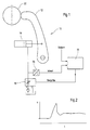
- Fig. 1 shows a schematic partial representation of a conventional winding device 10, in which the secondary lever 12 by a respective hydraulic cylinder 14th can be acted upon by means of a control device 16 via an actuator 18 can be controlled, which is designed as a proportional directional control valve or control valve.
- an actuator 18 can be simplified as an electrically adjustable throttle being represented.
- the pressure actually prevailing in the hydraulic cylinder 14 is detected by a pressure sensor 20 and fed to the control device 16.
- the actual pressure value obtained is stored in this higher-level control device 16 from the pressure sensor 20 with one supplied to the control device 16 external setpoint value compared, whereupon the control device 16 a corresponding Control signal for the proportional directional valve or control valve Actuator 18 calculates and outputs.
- 1 also shows the drum 22 of the winding device in question 10 recognizable.
- the invention has for its object an improved winding device to create of the type mentioned, in which the risk of occurrence of too high linear forces during the transition from the primary winding phase to the secondary winding phase is reduced or eliminated.
- Control device controllable secondary lever at least in the phase in which they are applied to the newly wound drum, over at least one provided between the control device and the secondary levers Pressure limiting element can be controlled.
- the force or pressure limitation thus takes place in a separate limiting element, that is provided between the control device and the secondary levers can be and leads to a correspondingly shorter reaction time.
- the Secondary levers can therefore without the risk of a large line force overshoot practically unrestrained on the newly wound drum become. It is not an elaborate, slow approach to the transfer point more needed. Commissioning, handover and possible troubleshooting is significantly simplified, with time being saved in particular.
- the force or pressure limiting element preferably comprises a pressure limiting valve.
- a pressure relief valve over a valve influencing the flow, such as a proportional directional control valve again consists in the fact that the actual pressure control or Limitation takes place directly in the valve itself and accordingly short Response times can be achieved.
- the force or pressure limiting valve can in particular be a directly controlled one Pressure relief valve include, in which the sealing cone when reaching the Set or set pressure against a spring force from the seat. there can the spring preload, for example mechanically and / or electrically be generated.
- the winding device is the force or pressure limiting element as an actuator for at least one hydraulic or pneumatic cylinder provided.
- the control device can be inactive in the application phase or a constant one Deliver the manipulated variable to the force or pressure limiting element.
- the manipulated variable is preferably selected so that the setting force or the setting pressure just above the force or the pressure for the process of Secondary lever is required.
- the line or Contact pressure controlled again, for example, according to external setpoints or be regulated.
- the force or pressure limiting element can be of the set pressure can be variably adjustable.
- This force or pressure limiting element can for example manually, electrically and / or electronically be adjustable.
- the pressure relief valve is activated expediently used as an actuator. Then no longer with constant setpoint, but in the classic pressure control loop with setpoint specification according to the selected line force and pressure feedback Pressure transducer.
- control device is used to control the Movement of the secondary levers each require minimal force or pressure in particular on the basis of determined actual values of the force or the pressure and based on determined changes in the angle of the secondary lever per unit of time can be specified.
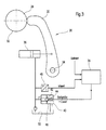
- Fig. 3 shows a schematic partial representation of an exemplary embodiment a device 26 according to the invention for winding a material web a reel 28.
- the material web can in particular be a Trade paper or cardboard web.
- the drum 28 guided by the primary lever in a primary winding phase becomes then passed from the primary levers to secondary levers 30 in order to Secondary winding phase to be wound further.
- the material web is guided over a carrier drum (not shown), which with the drum 28 or the winding 32 to be formed thereon a winding gap forms.
- the drum 28 is used to generate a line force in this winding gap via a drum holder, load lever or assigned to the primary levers the like or can be pressed against the carrying drum via the secondary lever 30.
- the secondary levers 30 pivotably mounted about an axis 34 are, for example actuated or pivoted via hydraulic cylinder 36.
- the secondary levers 30 that can be controlled by means of a control device 38 or Hydraulic cylinders 36 are at least in the phase in which they are on the newly wound Drum 28 can be created via at least one between the control device 38 and the secondary lever 30 or hydraulic cylinder 36 switchable Force or pressure limiting element controllable, that in the present case is formed for example by a pressure relief valve 40.
- a directly controlled pressure relief valve 40 provided, in which the sealing cone 42 when reaching the setting or Response pressure against the force of at least one spring 44 from the seat 46 takes off.
- the spring preload can be mechanical and / or electrical, for example be generated.
- the pressure relief valve 40 thus serves as an actuator for at least one the hydraulic cylinders 36 acting on the secondary levers 30. Via a pressure sensor 48, the actual pressure in the hydraulic cylinder 36 is detected and on the control device 38 passed on.
- the higher-level control device 38 compares that from the pressure sensor 48 actual pressure value obtained with an external, that is to say externally specified Setpoint to a corresponding control signal for the pressure relief valve 40 calculate and output.
- control device 38 is preferably inactive in the application phase, that is to say it can in particular supply a constant manipulated variable to the pressure limiting valve 40 in this application phase.
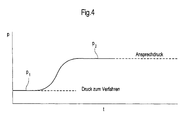
- the manipulated variable can in particular be selected such that the setting or response pressure is just above the pressure p 1 (cf. FIG. 4) that is required for moving the secondary lever 30.
- the setting or response pressure forming the limiting pressure is designated “p 2 " in FIG. 4.
- the line or contact pressure can be controlled using the control device 38 controlled, for example, according to the external setpoints be managed.
- the pressure relief valve is activated expediently used as an actuator. Then no longer with constant setpoint, but in the classic pressure control loop with setpoint specification according to the selected line force and pressure feedback Pressure transducer.
- the control device 38 can be used to move the secondary lever 30
- the minimum pressure required in each case, in particular on the basis of the actual pressure values determined and based on determined changes in the angle of the pivotable Secondary lever 38 can be specified per unit of time.
- there can be one secondary lever on the driver side and one on the drive side 30 each with an associated hydraulic cylinder 36 and pressure relief valve 40 may be provided.
- the directly controlled pressure relief valve 40 serves as a seat already mentioned, as an actuator for a respective associated hydraulic cylinder 36. It works as a force comparator. So is the one exerted by the hydraulic pressure Force (actual value) with the spring force, i.e. the force of at least one Spring 44 compared. The spring force in question results from the mechanical or electrically generated spring preload (setpoint). Exceeds the hydraulic Force the spring force, the sealing cone 42 lifts off the seat 46, whereby the Hydraulic cylinder 36 to the tank 50 is relieved.
- the higher-level control device is inactive during the entire application phase, so the output manipulated variable is constant. It is preferably chosen so that the setting or response pressure p 2 is just above the pressure p 1 that is required for moving the secondary arms 30 (cf. FIG. 4).
- the expected pressure curve was determined in test bench tests and is in the diagram shown in FIG. 4, from which it can be seen that the overshoot of the pressure and according to the line force during the transition eliminated from the primary winding phase into the secondary winding phase or at least is reduced to a minimum.
- a secondary lever 30 can be provided on each side his.
- the secondary lever 30 can now without the risk of a large line force overshoot practically without brakes on the newly wound drum 28 be created. It is not an elaborate, slow approach to the transfer point more needed. Commissioning is much easier, though especially time is saved. Switching to line force control the secondary lever 30 expediently only takes place when when the conditions are stable, i.e. the secondary lever movement is completed. The result is a better quality of the on the Primary levers of wrapped paper.
Landscapes
- Winding Of Webs (AREA)
- Replacement Of Web Rolls (AREA)
- Vehicle Step Arrangements And Article Storage (AREA)
- Liquid Crystal (AREA)
- Burglar Alarm Systems (AREA)
- Mechanically-Actuated Valves (AREA)
- Control Of Fluid Pressure (AREA)
- Servomotors (AREA)
Abstract
Description
- Fig. 1
- eine schematische Teildarstellung einer herkömmlichen Aufwickelvorrichtung,
- Fig. 2
- der sich in den Hydraulikzylindern der Aufwickelvorrichtung gemäß Fig. 1 in der Anlegephase ergebende zeitliche Druckverlauf,
- Fig. 3
- eine schematische Teildarstellung eines Ausführungsbeispiels einer erfindungsgemäßen Aufwickelvorrichtung und
- Fig. 4
- der sich in den Hydraulikzylindern der erfindungsgemäßen Aufwickelvorrichtung gemäß Fig. 3 in der Anlegephase ergebende zeitliche Druckverlauf.
- 10
- Aufwickelvorrichtung
- 12
- Sekundärhebel
- 14
- Hydraulikzylinder
- 16
- Steuereinrichtung
- 18
- Stellglied
- 20
- Druckaufnehmer
- 22
- Tambour
- 24
- Druckspitze
- 26
- Aufwickelvorrichtung
- 28
- Tambour
- 30
- Sekundärhebel
- 32
- Wickel
- 34
- Achse
- 36
- Hydraulikzylinder
- 38
- Steuereinrichtung
- 40
- Kraft- oder Druckbegrenzungselement, Druckbegrenzungsventil
- 42
- Dichtkegel
- 44
- Feder
- 46
- Sitz
- 48
- Druckaufnehmer
- 50
- Tank
- p1
- Druck zum Verfahren der Sekundärhebel
- p2
- Einstell- oder Ansprechdruck, Begrenzungsdruck
Claims (13)
- Vorrichtung (26) zum Aufwickeln einer Materialbahn, insbesondere Papier- oder Kartonbahn, auf einen Tambour (28), der in einer Primärwickelphase durch Primärhebel geführt ist und anschließend von den Primärhebeln an Sekundärhebel (30) übergeben wird, um in einer Sekundärwickelphase weiter bewickelt zu werden, wobei die Materialbahn über eine Tragtrommel geführt wird, zwischen dem Tambour (28) bzw. dem darauf zu bildenden Wickel und der Tragtrommel ein Wickelspalt gebildet ist und der Tambour (28) zur Erzeugung einer Linienkraft in dem Wickelspalt über einen den Primärhebeln zugeordneten Tambourhalter oder dergleichen bzw. über die Sekundärhebel (30) an die Tragtrommel anpressbar ist,
dadurch gekennzeichnet, dass die mittels einer Steuereinrichtung (38) ansteuerbaren Sekundärhebel (30) zumindest in der Phase, in der sie an den neu bewickelten Tambour (28) angelegt werden, über wenigstens ein zwischen der Steuereinrichtung (38) und den Sekundärhebeln (30) vorgesehenes Kraft- oder Druckbegrenzungselement (40) ansteuerbar sind. - Aufwickelvorrichtung nach Anspruch 1,
dadurch gekennzeichnet, dass das Kraft- bzw. Druckbegrenzungselement ein Druckbegrenzungsventil (40) umfasst. - Aufwickelvorrichtung nach Anspruch 2,
dadurch gekennzeichnet, dass das Kraft- bzw. Druckbegrenzungselement ein direkt gesteuertes Druckbegrenzungsventil (40) umfasst, bei dem der Dichtkegel (42) bei Erreichen des Einstelldrucks entgegen einer Federkraft vom Sitz (46) abhebt. - Aufwickelvorrichtung nach Anspruch 3,
dadurch gekennzeichnet, dass die Federvorspannung mechanisch und/oder elektrisch erzeugt ist. - Aufwickelvorrichtung nach einem der vorhergehenden Ansprüche,
dadurch gekennzeichnet, dass das Kraft- bzw. Druckbegrenzungselement (40) als Stellglied für wenigstens einen die Sekundärhebel (30) beaufschlagenden hydraulischen oder pneumatischen Zylinder (36) vorgesehen ist. - Aufwickelvorrichtung nach einem der vorhergehenden Ansprüche,
dadurch gekennzeichnet, dass die Steuereinrichtung (38) in der Anlegephase inaktiv ist bzw. eine konstante Stellgröße an das Kraft- bzw. Druckbegrenzungselement liefert. - Aufwickelvorrichtung nach Anspruch 6,
dadurch gekennzeichnet, dass die Stellgröße so gewählt ist, dass die Einstellkraft- bzw. der Einstelldruck knapp über der Kraft bzw. dem Druck (p1) liegt, die bzw. der für das Verfahren der Sekundärhebel erforderlich ist. - Aufwickelvorrichtung nach einem der vorhergehenden Ansprüche,
dadurch gekennzeichnet, dass nach der Anlegephase mittels der Steuereinrichtung (38) die Linien- bzw. Anpresskraft steuer- oder regelbar ist. - Aufwickelvorrichtung nach einem der vorhergehenden Ansprüche,
dadurch gekennzeichnet, dass das Kraft- bzw. Druckbegrenzungselement bezüglich der Einstellkraft bzw. des Einstelldrucks variabel einstellbar ist. - Aufwickelvorrichtung nach Anspruch 9,
dadurch gekennzeichnet, dass das Kraft- bzw. Druckbegrenzungselement manuell einstellbar ist. - Aufwickelvorrichtung nach Anspruch 9 oder 10,
dadurch gekennzeichnet, dass das Kraft- bzw. Druckbegrenzungselement elektrisch und/oder elektronisch einstellbar ist. - Aufwickelvorrichtung nach einem der vorhergehenden Ansprüche,
dadurch gekennzeichnet, dass mittels der Steuereinrichtung (38) die zum Verfahren der Sekundärhebel (30) jeweils minimal erforderliche Kraft bzw. Druck insbesondere anhand von ermittelten Istwerten der Kraft bzw. des Drucks und anhand von ermittelten Winkelveränderungen der Sekundärhebel (38) pro Zeiteinheit vorgebbar ist. - Aufwickelvorrichtung nach einem der vorhergehenden Ansprüche,
dadurch gekennzeichnet, dass auf beiden Seiten der Materialbahn jeweils wenigstens ein insbesondere elektronisch verstellbares Kraft- bzw. Druckbegrenzungselement (40) vorgesehen ist.
Applications Claiming Priority (2)
| Application Number | Priority Date | Filing Date | Title |
|---|---|---|---|
| DE10327245A DE10327245A1 (de) | 2003-06-17 | 2003-06-17 | Aufwickelvorrichtung |
| DE10327245 | 2003-06-17 |
Publications (3)
| Publication Number | Publication Date |
|---|---|
| EP1489029A2 true EP1489029A2 (de) | 2004-12-22 |
| EP1489029A3 EP1489029A3 (de) | 2007-04-18 |
| EP1489029B1 EP1489029B1 (de) | 2011-03-09 |
Family
ID=33394846
Family Applications (1)
| Application Number | Title | Priority Date | Filing Date |
|---|---|---|---|
| EP04102677A Expired - Lifetime EP1489029B1 (de) | 2003-06-17 | 2004-06-14 | Aufwickelvorrichtung |
Country Status (3)
| Country | Link |
|---|---|
| EP (1) | EP1489029B1 (de) |
| AT (1) | ATE501073T1 (de) |
| DE (2) | DE10327245A1 (de) |
Cited By (2)
| Publication number | Priority date | Publication date | Assignee | Title |
|---|---|---|---|---|
| WO2010043754A1 (en) * | 2008-10-17 | 2010-04-22 | Metso Paper, Inc. | Apparatus and method for winding up a fibrous web |
| CN103213862A (zh) * | 2013-04-26 | 2013-07-24 | 浙江晶鑫特种纸业有限公司 | 一种卷纸机 |
Citations (3)
| Publication number | Priority date | Publication date | Assignee | Title |
|---|---|---|---|---|
| US3614011A (en) | 1969-12-22 | 1971-10-19 | Beloit Corp | Nip relieving apparatus for a reel |
| DE3539980C2 (de) | 1984-11-27 | 1996-07-04 | Valmet Oy | Verfahren und Vorrichtung zur Steuerung eines Papierbahnaufrollers |
| DE10139340A1 (de) | 2001-08-10 | 2003-02-27 | Voith Paper Patent Gmbh | Aufwickelvorrichtung |
Family Cites Families (12)
| Publication number | Priority date | Publication date | Assignee | Title |
|---|---|---|---|---|
| US2837293A (en) * | 1955-06-27 | 1958-06-03 | Rice Barton Corp | Paper winding machine |
| US3877654A (en) * | 1973-10-01 | 1975-04-15 | Dominion Eng Works Ltd | Reel bar loading system |
| DE3347733A1 (de) * | 1983-12-31 | 1985-11-07 | Lenze GmbH & Co KG Aerzen, 3258 Aerzen | Kontaktwalzensteuerung fuer aufwickelvorrichtung |
| DE3627463A1 (de) * | 1986-08-13 | 1988-02-18 | Smg Stahlkontor Maschinenbau G | Vorrichtung zum regeln bzw. steuern einer kontaktwalze |
| IT1229851B (it) * | 1989-05-23 | 1991-09-13 | Dolci Spa L | Dispositivo per avvolgere materiali nastriformi. |
| US5370327A (en) * | 1993-05-06 | 1994-12-06 | Beloit Technologies, Inc. | Method and apparatus for reeling a wound web roll |
| SE505333C2 (sv) * | 1995-12-20 | 1997-08-11 | Nobel Elektronik Ab | Anordning för reglering av linjekraften i en rullstolsmaskin vid papperstillverkning |
| FI106446B (fi) * | 1998-02-04 | 2001-02-15 | Valmet Corp | Menetelmä rainan rullauksessa |
| DE19819276A1 (de) * | 1998-04-30 | 1999-11-04 | Hoechst Trespaphan Gmbh | Verfahren zur Regelung der Wickeldichte von Folienrollen |
| FI110363B (fi) * | 1998-09-22 | 2002-12-31 | Metso Paper Inc | Laitteisto rainan rullaimen yhteydessä |
| US6036137A (en) * | 1998-12-17 | 2000-03-14 | Valmet-Karlstad Ab | Apparatus and method for winding paper |
| DE50111144D1 (de) * | 2001-01-22 | 2006-11-16 | Andritz Ag Maschf | Verfahren und Vorrichtung zum kontinuierlichen Aufwickeln einer Faserstoffbahn |
-
2003
- 2003-06-17 DE DE10327245A patent/DE10327245A1/de not_active Withdrawn
-
2004
- 2004-06-14 EP EP04102677A patent/EP1489029B1/de not_active Expired - Lifetime
- 2004-06-14 DE DE502004012278T patent/DE502004012278D1/de not_active Expired - Lifetime
- 2004-06-14 AT AT04102677T patent/ATE501073T1/de active
Patent Citations (3)
| Publication number | Priority date | Publication date | Assignee | Title |
|---|---|---|---|---|
| US3614011A (en) | 1969-12-22 | 1971-10-19 | Beloit Corp | Nip relieving apparatus for a reel |
| DE3539980C2 (de) | 1984-11-27 | 1996-07-04 | Valmet Oy | Verfahren und Vorrichtung zur Steuerung eines Papierbahnaufrollers |
| DE10139340A1 (de) | 2001-08-10 | 2003-02-27 | Voith Paper Patent Gmbh | Aufwickelvorrichtung |
Cited By (2)
| Publication number | Priority date | Publication date | Assignee | Title |
|---|---|---|---|---|
| WO2010043754A1 (en) * | 2008-10-17 | 2010-04-22 | Metso Paper, Inc. | Apparatus and method for winding up a fibrous web |
| CN103213862A (zh) * | 2013-04-26 | 2013-07-24 | 浙江晶鑫特种纸业有限公司 | 一种卷纸机 |
Also Published As
| Publication number | Publication date |
|---|---|
| DE502004012278D1 (de) | 2011-04-21 |
| EP1489029B1 (de) | 2011-03-09 |
| ATE501073T1 (de) | 2011-03-15 |
| DE10327245A1 (de) | 2005-01-05 |
| EP1489029A3 (de) | 2007-04-18 |
Similar Documents
| Publication | Publication Date | Title |
|---|---|---|
| DE102005014416B4 (de) | Luftservozylindervorrichtung und Steuerverfahren hierfür | |
| DE102004012294B4 (de) | Hochgeschwindigkeitsantriebsverfahren und -system für Druckzylinder | |
| DE611362T1 (de) | Gelenkig gelagertes andruckrollensystem und verfahren hierfür. | |
| DE68913647T2 (de) | Pneumatisches Gesenkpolster. | |
| EP3524421B1 (de) | Presse und verfahren zu deren betrieb | |
| AT506398A4 (de) | Verfahren und vorrichtung zur unterdrückung von schwingungen in einer walzanlage | |
| DE3608182C2 (de) | ||
| DE4428929A1 (de) | Verfahren und Einrichtung zur Druckregelung | |
| DE4317846A1 (de) | Verfahren zur Einstellung eines Bremswertes auf einen Soll-Bremswert | |
| DE102004063463C5 (de) | Verfahren zur Steuerung einer Ausgleichszylindereinheit insbesondere für eine Schweißvorrichtung und Ausgleichszylindereinheit | |
| EP3592991B1 (de) | Verfahren zum ansteuern eines hydraulischen stellantriebes, steuereinrichtung und stellantriebsteuerung | |
| DE102018217337A1 (de) | Bewegungsvorrichtung, Reifenhandhabungsvorrichtung und Verfahren zum Betrieb eines fluidischen Aktors | |
| DE3240602C2 (de) | ||
| EP1489029B1 (de) | Aufwickelvorrichtung | |
| DE69001326T2 (de) | Elektrohydraulisches system. | |
| AT506493A2 (de) | Verfahren zum aufrollen einer papier- oder kartonbahn, und rollapparat | |
| DE2427466A1 (de) | Doppeltwirkende bremsvorrichtung fuer eine rollenschneidmaschine oder dgl. | |
| DE19731947A1 (de) | Verfahren zum Steuern bzw. Regeln einer Vorrichtung zum Auftragen eines flüssigen oder pastösen Mediums auf eine Gegenfläche | |
| DE4327313A1 (de) | Verfahren zur Druckregelung einer hydrostatischen Maschine mit verstellbarem Fördervolumen | |
| AT500476A1 (de) | Druckmittelzylinder mit druckübersetzung | |
| DE29811053U1 (de) | Vorrichtung zum Aufwickeln von bahnförmigem Gut | |
| DE4112666C2 (de) | Vorrichtung zur Fernbedienung von Klemmeinrichtungen an Zylindern in Rotationsdruckmaschinen | |
| DE10302666B4 (de) | Verfahren und Anordnung zum Kontrollieren eines Streichspalts | |
| DE102005028334A1 (de) | Vorrichtung und ein Verfahren zur Regelung der Bahnspannung | |
| DE69833479T2 (de) | Verfahren und Vorrichtung zur automatischen Überwachung und Korrektur des Regulierungsdrucks in den Regulierungsventilen einer Durchbiegungseinstellwalze in einer Papiermaschine |
Legal Events
| Date | Code | Title | Description |
|---|---|---|---|
| PUAI | Public reference made under article 153(3) epc to a published international application that has entered the european phase |
Free format text: ORIGINAL CODE: 0009012 |
|
| AK | Designated contracting states |
Kind code of ref document: A2 Designated state(s): AT BE BG CH CY CZ DE DK EE ES FI FR GB GR HU IE IT LI LU MC NL PL PT RO SE SI SK TR |
|
| AX | Request for extension of the european patent |
Extension state: AL HR LT LV MK |
|
| RAP1 | Party data changed (applicant data changed or rights of an application transferred) |
Owner name: VOITH PATENT GMBH |
|
| PUAL | Search report despatched |
Free format text: ORIGINAL CODE: 0009013 |
|
| AK | Designated contracting states |
Kind code of ref document: A3 Designated state(s): AT BE BG CH CY CZ DE DK EE ES FI FR GB GR HU IE IT LI LU MC NL PL PT RO SE SI SK TR |
|
| AX | Request for extension of the european patent |
Extension state: AL HR LT LV MK |
|
| 17P | Request for examination filed |
Effective date: 20071018 |
|
| AKX | Designation fees paid |
Designated state(s): AT BE BG CH CY CZ DE DK EE ES FI FR GB GR HU IE IT LI LU MC NL PL PT RO SE SI SK TR |
|
| 17Q | First examination report despatched |
Effective date: 20100319 |
|
| GRAP | Despatch of communication of intention to grant a patent |
Free format text: ORIGINAL CODE: EPIDOSNIGR1 |
|
| GRAS | Grant fee paid |
Free format text: ORIGINAL CODE: EPIDOSNIGR3 |
|
| GRAA | (expected) grant |
Free format text: ORIGINAL CODE: 0009210 |
|
| AK | Designated contracting states |
Kind code of ref document: B1 Designated state(s): AT BE BG CH CY CZ DE DK EE ES FI FR GB GR HU IE IT LI LU MC NL PL PT RO SE SI SK TR |
|
| REG | Reference to a national code |
Ref country code: GB Ref legal event code: FG4D Free format text: NOT ENGLISH |
|
| REG | Reference to a national code |
Ref country code: CH Ref legal event code: EP |
|
| REG | Reference to a national code |
Ref country code: IE Ref legal event code: FG4D Free format text: LANGUAGE OF EP DOCUMENT: GERMAN |
|
| REF | Corresponds to: |
Ref document number: 502004012278 Country of ref document: DE Date of ref document: 20110421 Kind code of ref document: P |
|
| REG | Reference to a national code |
Ref country code: DE Ref legal event code: R096 Ref document number: 502004012278 Country of ref document: DE Effective date: 20110421 |
|
| REG | Reference to a national code |
Ref country code: NL Ref legal event code: VDEP Effective date: 20110309 |
|
| PG25 | Lapsed in a contracting state [announced via postgrant information from national office to epo] |
Ref country code: ES Free format text: LAPSE BECAUSE OF FAILURE TO SUBMIT A TRANSLATION OF THE DESCRIPTION OR TO PAY THE FEE WITHIN THE PRESCRIBED TIME-LIMIT Effective date: 20110620 Ref country code: SE Free format text: LAPSE BECAUSE OF FAILURE TO SUBMIT A TRANSLATION OF THE DESCRIPTION OR TO PAY THE FEE WITHIN THE PRESCRIBED TIME-LIMIT Effective date: 20110309 Ref country code: GR Free format text: LAPSE BECAUSE OF FAILURE TO SUBMIT A TRANSLATION OF THE DESCRIPTION OR TO PAY THE FEE WITHIN THE PRESCRIBED TIME-LIMIT Effective date: 20110610 |
|
| PG25 | Lapsed in a contracting state [announced via postgrant information from national office to epo] |
Ref country code: SI Free format text: LAPSE BECAUSE OF FAILURE TO SUBMIT A TRANSLATION OF THE DESCRIPTION OR TO PAY THE FEE WITHIN THE PRESCRIBED TIME-LIMIT Effective date: 20110309 Ref country code: NL Free format text: LAPSE BECAUSE OF FAILURE TO SUBMIT A TRANSLATION OF THE DESCRIPTION OR TO PAY THE FEE WITHIN THE PRESCRIBED TIME-LIMIT Effective date: 20110309 Ref country code: BG Free format text: LAPSE BECAUSE OF FAILURE TO SUBMIT A TRANSLATION OF THE DESCRIPTION OR TO PAY THE FEE WITHIN THE PRESCRIBED TIME-LIMIT Effective date: 20110609 Ref country code: CY Free format text: LAPSE BECAUSE OF FAILURE TO SUBMIT A TRANSLATION OF THE DESCRIPTION OR TO PAY THE FEE WITHIN THE PRESCRIBED TIME-LIMIT Effective date: 20110309 |
|
| PGFP | Annual fee paid to national office [announced via postgrant information from national office to epo] |
Ref country code: AT Payment date: 20110613 Year of fee payment: 8 Ref country code: FI Payment date: 20110613 Year of fee payment: 8 |
|
| PGFP | Annual fee paid to national office [announced via postgrant information from national office to epo] |
Ref country code: DE Payment date: 20110622 Year of fee payment: 8 |
|
| REG | Reference to a national code |
Ref country code: IE Ref legal event code: FD4D |
|
| PG25 | Lapsed in a contracting state [announced via postgrant information from national office to epo] |
Ref country code: IE Free format text: LAPSE BECAUSE OF FAILURE TO SUBMIT A TRANSLATION OF THE DESCRIPTION OR TO PAY THE FEE WITHIN THE PRESCRIBED TIME-LIMIT Effective date: 20110309 Ref country code: EE Free format text: LAPSE BECAUSE OF FAILURE TO SUBMIT A TRANSLATION OF THE DESCRIPTION OR TO PAY THE FEE WITHIN THE PRESCRIBED TIME-LIMIT Effective date: 20110309 Ref country code: PT Free format text: LAPSE BECAUSE OF FAILURE TO SUBMIT A TRANSLATION OF THE DESCRIPTION OR TO PAY THE FEE WITHIN THE PRESCRIBED TIME-LIMIT Effective date: 20110711 |
|
| PG25 | Lapsed in a contracting state [announced via postgrant information from national office to epo] |
Ref country code: CZ Free format text: LAPSE BECAUSE OF FAILURE TO SUBMIT A TRANSLATION OF THE DESCRIPTION OR TO PAY THE FEE WITHIN THE PRESCRIBED TIME-LIMIT Effective date: 20110309 Ref country code: RO Free format text: LAPSE BECAUSE OF FAILURE TO SUBMIT A TRANSLATION OF THE DESCRIPTION OR TO PAY THE FEE WITHIN THE PRESCRIBED TIME-LIMIT Effective date: 20110309 Ref country code: SK Free format text: LAPSE BECAUSE OF FAILURE TO SUBMIT A TRANSLATION OF THE DESCRIPTION OR TO PAY THE FEE WITHIN THE PRESCRIBED TIME-LIMIT Effective date: 20110309 |
|
| PGFP | Annual fee paid to national office [announced via postgrant information from national office to epo] |
Ref country code: IT Payment date: 20110621 Year of fee payment: 8 |
|
| BERE | Be: lapsed |
Owner name: VOITH PATENT G.M.B.H. Effective date: 20110630 |
|
| PLBE | No opposition filed within time limit |
Free format text: ORIGINAL CODE: 0009261 |
|
| STAA | Information on the status of an ep patent application or granted ep patent |
Free format text: STATUS: NO OPPOSITION FILED WITHIN TIME LIMIT |
|
| REG | Reference to a national code |
Ref country code: CH Ref legal event code: PL |
|
| 26N | No opposition filed |
Effective date: 20111212 |
|
| GBPC | Gb: european patent ceased through non-payment of renewal fee |
Effective date: 20110614 |
|
| PG25 | Lapsed in a contracting state [announced via postgrant information from national office to epo] |
Ref country code: PL Free format text: LAPSE BECAUSE OF FAILURE TO SUBMIT A TRANSLATION OF THE DESCRIPTION OR TO PAY THE FEE WITHIN THE PRESCRIBED TIME-LIMIT Effective date: 20110309 Ref country code: DK Free format text: LAPSE BECAUSE OF FAILURE TO SUBMIT A TRANSLATION OF THE DESCRIPTION OR TO PAY THE FEE WITHIN THE PRESCRIBED TIME-LIMIT Effective date: 20110309 |
|
| REG | Reference to a national code |
Ref country code: FR Ref legal event code: ST Effective date: 20120229 |
|
| PG25 | Lapsed in a contracting state [announced via postgrant information from national office to epo] |
Ref country code: BE Free format text: LAPSE BECAUSE OF NON-PAYMENT OF DUE FEES Effective date: 20110630 |
|
| REG | Reference to a national code |
Ref country code: DE Ref legal event code: R097 Ref document number: 502004012278 Country of ref document: DE Effective date: 20111212 |
|
| PG25 | Lapsed in a contracting state [announced via postgrant information from national office to epo] |
Ref country code: FR Free format text: LAPSE BECAUSE OF NON-PAYMENT OF DUE FEES Effective date: 20110630 Ref country code: CH Free format text: LAPSE BECAUSE OF NON-PAYMENT OF DUE FEES Effective date: 20110630 Ref country code: LI Free format text: LAPSE BECAUSE OF NON-PAYMENT OF DUE FEES Effective date: 20110630 |
|
| PG25 | Lapsed in a contracting state [announced via postgrant information from national office to epo] |
Ref country code: GB Free format text: LAPSE BECAUSE OF NON-PAYMENT OF DUE FEES Effective date: 20110614 |
|
| PG25 | Lapsed in a contracting state [announced via postgrant information from national office to epo] |
Ref country code: FI Free format text: LAPSE BECAUSE OF NON-PAYMENT OF DUE FEES Effective date: 20120614 |
|
| REG | Reference to a national code |
Ref country code: AT Ref legal event code: MM01 Ref document number: 501073 Country of ref document: AT Kind code of ref document: T Effective date: 20120614 |
|
| PG25 | Lapsed in a contracting state [announced via postgrant information from national office to epo] |
Ref country code: IT Free format text: LAPSE BECAUSE OF NON-PAYMENT OF DUE FEES Effective date: 20120614 |
|
| REG | Reference to a national code |
Ref country code: DE Ref legal event code: R119 Ref document number: 502004012278 Country of ref document: DE Effective date: 20130101 |
|
| PG25 | Lapsed in a contracting state [announced via postgrant information from national office to epo] |
Ref country code: MC Free format text: LAPSE BECAUSE OF NON-PAYMENT OF DUE FEES Effective date: 20110630 Ref country code: DE Free format text: LAPSE BECAUSE OF NON-PAYMENT OF DUE FEES Effective date: 20130101 |
|
| PG25 | Lapsed in a contracting state [announced via postgrant information from national office to epo] |
Ref country code: LU Free format text: LAPSE BECAUSE OF NON-PAYMENT OF DUE FEES Effective date: 20110614 |
|
| PG25 | Lapsed in a contracting state [announced via postgrant information from national office to epo] |
Ref country code: AT Free format text: LAPSE BECAUSE OF NON-PAYMENT OF DUE FEES Effective date: 20120614 |
|
| PG25 | Lapsed in a contracting state [announced via postgrant information from national office to epo] |
Ref country code: TR Free format text: LAPSE BECAUSE OF FAILURE TO SUBMIT A TRANSLATION OF THE DESCRIPTION OR TO PAY THE FEE WITHIN THE PRESCRIBED TIME-LIMIT Effective date: 20110309 |
|
| PG25 | Lapsed in a contracting state [announced via postgrant information from national office to epo] |
Ref country code: HU Free format text: LAPSE BECAUSE OF FAILURE TO SUBMIT A TRANSLATION OF THE DESCRIPTION OR TO PAY THE FEE WITHIN THE PRESCRIBED TIME-LIMIT Effective date: 20110309 |