EP1489324A2 - Dispositif d'embrayage, notamment dispositif d'embrayage double ou multiple et concept d'étanchéité - Google Patents
Dispositif d'embrayage, notamment dispositif d'embrayage double ou multiple et concept d'étanchéité Download PDFInfo
- Publication number
- EP1489324A2 EP1489324A2 EP04013298A EP04013298A EP1489324A2 EP 1489324 A2 EP1489324 A2 EP 1489324A2 EP 04013298 A EP04013298 A EP 04013298A EP 04013298 A EP04013298 A EP 04013298A EP 1489324 A2 EP1489324 A2 EP 1489324A2
- Authority
- EP
- European Patent Office
- Prior art keywords
- sealing
- arrangement
- coupling device
- sealing element
- plate spring
- Prior art date
- Legal status (The legal status is an assumption and is not a legal conclusion. Google has not performed a legal analysis and makes no representation as to the accuracy of the status listed.)
- Granted
Links
- 238000007789 sealing Methods 0.000 title claims abstract description 88
- 230000008878 coupling Effects 0.000 claims description 25
- 238000010168 coupling process Methods 0.000 claims description 25
- 238000005859 coupling reaction Methods 0.000 claims description 25
- 230000005540 biological transmission Effects 0.000 claims description 6
- 239000003921 oil Substances 0.000 description 5
- 210000002105 tongue Anatomy 0.000 description 3
- 229910000831 Steel Inorganic materials 0.000 description 2
- 230000006835 compression Effects 0.000 description 2
- 238000007906 compression Methods 0.000 description 2
- 238000001816 cooling Methods 0.000 description 2
- 239000000463 material Substances 0.000 description 2
- 239000010959 steel Substances 0.000 description 2
- 241000446313 Lamella Species 0.000 description 1
- 238000010521 absorption reaction Methods 0.000 description 1
- 239000011324 bead Substances 0.000 description 1
- 239000010720 hydraulic oil Substances 0.000 description 1
- 238000010348 incorporation Methods 0.000 description 1
- 230000006698 induction Effects 0.000 description 1
- 239000007769 metal material Substances 0.000 description 1
- 238000005121 nitriding Methods 0.000 description 1
Images
Classifications
-
- F—MECHANICAL ENGINEERING; LIGHTING; HEATING; WEAPONS; BLASTING
- F16—ENGINEERING ELEMENTS AND UNITS; GENERAL MEASURES FOR PRODUCING AND MAINTAINING EFFECTIVE FUNCTIONING OF MACHINES OR INSTALLATIONS; THERMAL INSULATION IN GENERAL
- F16D—COUPLINGS FOR TRANSMITTING ROTATION; CLUTCHES; BRAKES
- F16D25/00—Fluid-actuated clutches
- F16D25/06—Fluid-actuated clutches in which the fluid actuates a piston incorporated in, i.e. rotating with the clutch
- F16D25/062—Fluid-actuated clutches in which the fluid actuates a piston incorporated in, i.e. rotating with the clutch the clutch having friction surfaces
- F16D25/063—Fluid-actuated clutches in which the fluid actuates a piston incorporated in, i.e. rotating with the clutch the clutch having friction surfaces with clutch members exclusively moving axially
- F16D25/0635—Fluid-actuated clutches in which the fluid actuates a piston incorporated in, i.e. rotating with the clutch the clutch having friction surfaces with clutch members exclusively moving axially with flat friction surfaces, e.g. discs
- F16D25/0638—Fluid-actuated clutches in which the fluid actuates a piston incorporated in, i.e. rotating with the clutch the clutch having friction surfaces with clutch members exclusively moving axially with flat friction surfaces, e.g. discs with more than two discs, e.g. multiple lamellae
-
- F—MECHANICAL ENGINEERING; LIGHTING; HEATING; WEAPONS; BLASTING
- F16—ENGINEERING ELEMENTS AND UNITS; GENERAL MEASURES FOR PRODUCING AND MAINTAINING EFFECTIVE FUNCTIONING OF MACHINES OR INSTALLATIONS; THERMAL INSULATION IN GENERAL
- F16D—COUPLINGS FOR TRANSMITTING ROTATION; CLUTCHES; BRAKES
- F16D25/00—Fluid-actuated clutches
- F16D25/10—Clutch systems with a plurality of fluid-actuated clutches
-
- F—MECHANICAL ENGINEERING; LIGHTING; HEATING; WEAPONS; BLASTING
- F16—ENGINEERING ELEMENTS AND UNITS; GENERAL MEASURES FOR PRODUCING AND MAINTAINING EFFECTIVE FUNCTIONING OF MACHINES OR INSTALLATIONS; THERMAL INSULATION IN GENERAL
- F16D—COUPLINGS FOR TRANSMITTING ROTATION; CLUTCHES; BRAKES
- F16D21/00—Systems comprising a plurality of actuated clutches
- F16D21/02—Systems comprising a plurality of actuated clutches for interconnecting three or more shafts or other transmission members in different ways
- F16D21/06—Systems comprising a plurality of actuated clutches for interconnecting three or more shafts or other transmission members in different ways at least two driving shafts or two driven shafts being concentric
- F16D2021/0661—Hydraulically actuated multiple lamellae clutches
Definitions
- the invention relates to a coupling device, which by means of a Integrated pressure medium power cylinder is actuated, which one Pressure compensation space is assigned, with a restoring element on a Sealing arrangement of the compensation space is performed.
- Coupling devices are already known (e.g. DE 101 11 202 A1) in which a wet-running double clutch has been described, which has two radial arranged multi-plate clutch arrangements, each by means of a integrated pressure medium power cylinder can be actuated.
- These cylinders face axially displaceable actuating pistons, which by means of the cylinders Sealing arrangements are sealed, the sealing arrangements made of Sealing element holders and vulcanized sealing elements are constructed.
- the sealing element holders are welded to the cylinder walls.
- the Pressure medium power cylinders are each assigned a pressure compensation space, whereby only the pressure compensation space of the radially outer clutch is the same radial Extent has like the assigned pressure space of the Pressure medium power cylinder.
- the pressure equalization chamber is sealed here via an elastic sealing element, which is vulcanized onto the piston.
- the pressure compensation chamber of the pressure medium power cylinder which is the radially inner one Coupled arrangement actuated, is formed from the actuating piston of the inner Coupling arrangement and a boundary wall which is an elastic Receives sealing element that radially seals the pressure compensation chamber, wherein the sealing element of the pressure compensation space is arranged radially further out is like the sealing element that seals the pressure chamber.
- an axial cooling oil hole in the boundary wall provided that the radial region of the centrifugal force effective Pressure compensation space limited radially inwards.
- the reset of the pistons of the two multi-plate clutches takes place via plate spring arrangements, the Resetting the piston of the radially inner clutch via two in the same direction
- Layered disc springs which is between the piston of the radially inner Coupling and the boundary wall of the compensation space are arranged.
- These disc springs are centered over the radially inner circumference of the Disc springs, since here the spring tongues on an axial area of the Boundary walls are arranged.
- a disadvantage of this arrangement of the return springs of the radially inner clutch is that the spring arrangement is centered radially on the inside. Disc springs after have spring tongues directed radially inwards, change when deflected system-related their inner radius, while the outer radius essentially remains constant. For this reason, the disc springs must be centered radially Sufficiently large clearance is provided so that the compression when Do not clamp spring tongues on their seat. This in turn is an exact one Centering of the disc springs disadvantageously, since in the unactuated state Multi-plate clutch, the disc spring has its largest diameter radially on the inside and is therefore insufficiently centered in these operating states.
- the invention provides that Reset element on its radial outer circumference on a seal arrangement is led.
- the advantage here is that no additional component is arranged must to ensure a radial absorption of the restoring element.
- the return element of the actuating piston is within it assigned pressure equalization space and is located radially on the outside associated sealing arrangement performed.
- To design return element as a plate spring element arrangement is provided.
- An advantageous one Design of the plate spring arrangement provides this depending on required restoring forces and possibly several radially to extend the diaphragm springs in the same direction.
- the advantage here is that at Use disc springs in the axial area, which leads to a safe Radial guidance of the restoring element is required, which is relatively narrow in comparison for the use of axially extending spiral springs.
- the plate spring arrangement radially within an axially extending section of a sealing element holder.
- the associated sealing element is preferably arranged on the outer circumference of this axial section, so that the plate spring arrangement is guided directly on the sealing element holder, which is preferably made of metallic material.
- the sealing element holder additionally takes over the guidance of the plate spring arrangement and thus the outer radius of the plate spring arrangement can be maximized.
- a further advantageous embodiment of the invention provides for a separate component to be provided between the outer circumference of the plate spring arrangement and the sealing element holder, which is designed in the form of a socket and has an axial guide section which centers the plate spring arrangement.
- An embodiment of the sealing element holder according to the invention provides that they are welded to the cylinder wall and / or to the actuating piston, preferably a radially designed part of the sealing element holder, which takes over the radial guidance of the restoring element, has a contact area which is designed as a circumferential bead in the axial direction and on which the restoring element rests axially.
- the restoring element is preferably designed as a plate spring arrangement and the contact area is designed such that, when the actuating piston is axially displaced, it is possible for the plate spring arrangement to deflect into an over-dead center position, the plate spring arrangement only abutting the contact area of the sealing element holder.
- a further embodiment of the contact area according to the invention provides for a contact washer to be installed which is separate from the sealing element holder and which is also centered by the axial part of the sealing element holder.
- the contact area and / or the sealing element holder carrying the contact area and / or the separate contact disk is made of hard steel or hardened.
- the plate spring arrangement which executes radial movements in the region of the contact area when it compresses and rebounds, does not essentially work into the material in contact.
- the material in the contact area can be hardened, for example, by induction hardening or nitriding.
- both the radially outer and the radially inner contact area of the plate spring arrangement are designed to be wear-resistant against incorporation of the plate spring arrangement.
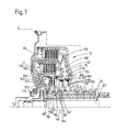
- FIG. 1 shows a double clutch device according to the invention with a preferred embodiment of the sealing arrangements.
- FIG. 1 shows a clutch device 12 which is designed as a double clutch with two radially arranged clutch arrangements 64, 72.
- the two clutch arrangements are actuated hydraulically by means of the actuating pistons 110, 130, pressure medium, preferably hydraulic oil, being conveyed into the two pressure medium power cylinders 118, 140 via a hydraulic unit (not shown).
- the pressure medium power cylinders 118, 140 are sealed radially on the outside by means of the sealing arrangements 112, 134 and radially on the inside by means of seals which are vulcanized onto the inner circumference of the two actuating pistons 110, 130.
- the two sealing arrangements 112, 134 each consist of a sealing element holder 150, 154 and a sealing element 160, 164 vulcanized thereon.
- the sealing element holders 150, 154 are each welded to the cylinder walls 62, 70.
- the seal arrangement 134 of the inner clutch is mounted on a larger radius than the seal arrangement 112, so that, despite the smaller diameter of the inner clutch, an essentially identical torque can be transmitted due to the larger piston area at the same actuation pressure.
- the two pressure medium power cylinders 118, 140 are each assigned a pressure compensation space 120, 122, the pressure compensation space 122 of the outer clutch arrangement 64 being formed from the piston 110 of the clutch arrangement 64 and the cylinder wall 70 of the inner clutch arrangement 72 and being sealed by means of the seal arrangement 114.
- the sealing arrangement 114 in turn consists of a sealing element holder 152 and a sealing element 162, the sealing element holder 152 being welded to the actuating piston 110.
- the sealing element 162 is vulcanized onto an axial section of the sealing element holder 152 and stiffened by the latter in the radial direction, so that the sealing element 162 cannot fold over radially outward at high speeds and the resulting centrifugal pressure.
- Another advantage of this configuration of the sealing arrangement 114 is that relatively large travels of the actuating piston 110 can be realized. The travel of the piston is proportional to the number of lamellae in a lamella package and therefore the piston geometry had to be adapted to the desired travel path.
- the configuration of the sealing arrangement according to the invention now allows the travel of the piston to be optimized by means of a specific configuration, so that identical pistons can be used in different clutches with a different number of plates.
- the pressure compensation chamber 122 of the inner clutch arrangement 72 is formed from the actuating piston 130 and the boundary wall 142, the sealing arrangement 136 sealing the pressure compensation chamber 122 radially outward.
- the sealing arrangement 136 is formed by the sealing element 166 and the sealing element holder 156, the sealing element holder 156 being welded to the actuating piston 130.
- the piston 130 is pressed back into its initial position by the restoring element 172, which is designed as a plate spring arrangement 174 with two plate springs layered in the same direction.
- the two plate springs press radially on the outside axially against the sealing element holder 156.
- the contact area 180 of the sealing element holder 156 is designed for this purpose in a bead-like manner, so that the contact area 180 is axially somewhat distant from the actuating piston 130, so that when the piston is moved, the contact area 180 remains essentially constant and a compression of the two disc springs in a so-called over-center position can be made possible.
- the contact area 180 is hard to counteract wear.
- either the complete sealing element holder 156 can be made of wear-resistant steel or only the contact area 180 can be hardened. A separate hardening of the actuating piston 130 in the contact area of the restoring element is therefore no longer necessary.
- the plate spring arrangement 174 is supported on the boundary wall 142 radially on the inside by means of the contact disk 190, which serves as wear protection.
- the boundary wall can be made wear-resistant in this area, for example by hardening, instead of the contact washer.
- the sealing arrangement 136 serves as a centering of the plate spring arrangement 174.
- an axial section 176 of the sealing element holder 156 engages radially over the outer circumference of the two plate springs, as a result of which they are held in their radial position.
- the sealing element holder 156 is provided with the sealing element 166 only on its radial outer side.
- the arrangement of the sealing arrangement 136 on the actuating piston 130 enables the pressure compensation chamber 122 of the inner clutch arrangement 72 to be arranged on the same radial diameter as the pressure medium power cylinder 140, as a result of which a bore in the boundary wall 142 which delimits the oil column is no longer required, which bore is full when the coupling device 12 is filled with cooling oil overcompensation of centrifugal force.
- a bore in the boundary wall 142 which delimits the oil column is no longer required, which bore is full when the coupling device 12 is filled with cooling oil overcompensation of centrifugal force.
Landscapes
- Engineering & Computer Science (AREA)
- General Engineering & Computer Science (AREA)
- Mechanical Engineering (AREA)
- Hydraulic Clutches, Magnetic Clutches, Fluid Clutches, And Fluid Joints (AREA)
Applications Claiming Priority (2)
| Application Number | Priority Date | Filing Date | Title |
|---|---|---|---|
| DE10327729 | 2003-06-18 | ||
| DE10327729A DE10327729A1 (de) | 2003-06-18 | 2003-06-18 | Kupplungseinrichtung, insbesondere Doppel- oder Mehrfachkupplungseinrichtung, und Dichtungskonzept hierfür |
Publications (3)
| Publication Number | Publication Date |
|---|---|
| EP1489324A2 true EP1489324A2 (fr) | 2004-12-22 |
| EP1489324A3 EP1489324A3 (fr) | 2005-06-08 |
| EP1489324B1 EP1489324B1 (fr) | 2006-10-11 |
Family
ID=33394902
Family Applications (1)
| Application Number | Title | Priority Date | Filing Date |
|---|---|---|---|
| EP04013298A Expired - Lifetime EP1489324B1 (fr) | 2003-06-18 | 2004-06-05 | Dispositif d'embrayage, notamment dispositif d'embrayage double ou multiple et concept d'étanchéité |
Country Status (2)
| Country | Link |
|---|---|
| EP (1) | EP1489324B1 (fr) |
| DE (2) | DE10327729A1 (fr) |
Cited By (1)
| Publication number | Priority date | Publication date | Assignee | Title |
|---|---|---|---|---|
| EP2988014A1 (fr) | 2014-08-01 | 2016-02-24 | Valeo Embrayages | Dispositif d'embrayage pour un véhicule automobile |
Families Citing this family (2)
| Publication number | Priority date | Publication date | Assignee | Title |
|---|---|---|---|---|
| DE102008016269B4 (de) | 2008-03-29 | 2019-08-08 | Borgwarner Inc. | Betätigungskolben für eine Reibkupplung und Reibkupplung mit einem solchen Betätigungskolben |
| DE102018122386B4 (de) * | 2018-09-13 | 2025-07-10 | Schaeffler Technologies AG & Co. KG | Doppelkupplungseinrichtung für einen Antriebsstrang eines Kraftfahrzeuges mit vollhydraulischer Betätigung |
Citations (1)
| Publication number | Priority date | Publication date | Assignee | Title |
|---|---|---|---|---|
| DE10111202A1 (de) | 2000-12-07 | 2002-06-13 | Zf Sachs Ag | Kupplungseinrichtung, insbesondere Doppel-oder Mehrfach-Kupplungseinrichtung, und Dichtungskonzept hierfür |
Family Cites Families (2)
| Publication number | Priority date | Publication date | Assignee | Title |
|---|---|---|---|---|
| DE19833377A1 (de) * | 1998-07-24 | 1999-12-09 | Getrag Getriebe Zahnrad | Doppelkupplung |
| DE10203618A1 (de) * | 2001-07-31 | 2003-02-13 | Zf Sachs Ag | Mehrfach-Kupplungseinrichtung |
-
2003
- 2003-06-18 DE DE10327729A patent/DE10327729A1/de not_active Withdrawn
-
2004
- 2004-06-05 DE DE502004001704T patent/DE502004001704D1/de not_active Expired - Lifetime
- 2004-06-05 EP EP04013298A patent/EP1489324B1/fr not_active Expired - Lifetime
Patent Citations (2)
| Publication number | Priority date | Publication date | Assignee | Title |
|---|---|---|---|---|
| DE10111202A1 (de) | 2000-12-07 | 2002-06-13 | Zf Sachs Ag | Kupplungseinrichtung, insbesondere Doppel-oder Mehrfach-Kupplungseinrichtung, und Dichtungskonzept hierfür |
| DE10124213A1 (de) | 2000-12-07 | 2002-06-13 | Zf Sachs Ag | Kupplungseirichtung mit einer wenigstens zwei gleichsinnig geschichtete Tellerfedern aufweisenden Tellerfederanordnung |
Cited By (1)
| Publication number | Priority date | Publication date | Assignee | Title |
|---|---|---|---|---|
| EP2988014A1 (fr) | 2014-08-01 | 2016-02-24 | Valeo Embrayages | Dispositif d'embrayage pour un véhicule automobile |
Also Published As
| Publication number | Publication date |
|---|---|
| DE502004001704D1 (de) | 2006-11-23 |
| EP1489324A3 (fr) | 2005-06-08 |
| EP1489324B1 (fr) | 2006-10-11 |
| DE10327729A1 (de) | 2005-01-05 |
Similar Documents
| Publication | Publication Date | Title |
|---|---|---|
| DE69520336T2 (de) | Nasskupplungseinheit | |
| DE10223780C1 (de) | Gangschaltgetriebe für ein Kraftfahrzeug mit hydraulisch betätigbarer Mehrfachkupplung | |
| DE102004012948B4 (de) | Doppelkupplungseinrichtung in axialer Bauart | |
| DE4206100B4 (de) | Schaltbares Planetengetriebe | |
| EP2145118B1 (fr) | Unité d'actionnement d'embrayage en fonction d'une différence couple/vitesse pour véhicules à moteur | |
| DE10064459B4 (de) | Doppelkupplung, insbesondere für Kraftfahrzeuge | |
| WO2017211340A1 (fr) | Dispositif d'accouplement | |
| WO2018091026A1 (fr) | Dispositif d'embrayage | |
| EP3610167B1 (fr) | Système d'embrayage, système de boîte de vitesses à double embrayage et véhicule à moteur | |
| EP1436518B1 (fr) | Systeme d'embrayage | |
| DE102010021899A1 (de) | Kupplung, insbesondere Doppelkupplung | |
| DE20310015U1 (de) | Kupplungseinrichtung, insbesondere Doppel- oder Mehrfachkupplungseinrichtung, und Dichtungskonzept hierfür | |
| EP1780435A2 (fr) | Embrayage double en forme radial | |
| EP2116734B1 (fr) | Couplage double | |
| EP1489324B1 (fr) | Dispositif d'embrayage, notamment dispositif d'embrayage double ou multiple et concept d'étanchéité | |
| EP1764523B2 (fr) | Dispositif d'embrayage à disques multiples | |
| WO2009021582A1 (fr) | Dispositif d'embrayage avec compensation des fuites d'huile améliorée | |
| EP1489328B1 (fr) | Dispositif d'embrayage à disques multiples. | |
| WO2012052498A1 (fr) | Embrayage ou frein à friction actionné par un fluide sous pression | |
| DE102019128300B3 (de) | Antriebsanordnung für ein Kraftfahrzeug | |
| EP2317186B1 (fr) | Système d'actionnement dans une transmission pour deux éléments de passage de vitesses actionnables sous pression | |
| DE10210177A1 (de) | Reibungskupplung mit separat ansteuerbarer Getriebebremse | |
| DE102008040109A1 (de) | Anordnung zur wahlweisen Drehkopplung einer Eingangswelle, insbesondere eines Kompressors in einem Fahrzeug, mit einem Antriebsorgan, insbesondere Antriebsrad | |
| DE102018122386B4 (de) | Doppelkupplungseinrichtung für einen Antriebsstrang eines Kraftfahrzeuges mit vollhydraulischer Betätigung | |
| EP3696436B1 (fr) | Dispositif d'embrayage pour une machine de travail agricole |
Legal Events
| Date | Code | Title | Description |
|---|---|---|---|
| PUAI | Public reference made under article 153(3) epc to a published international application that has entered the european phase |
Free format text: ORIGINAL CODE: 0009012 |
|
| AK | Designated contracting states |
Kind code of ref document: A2 Designated state(s): AT BE BG CH CY CZ DE DK EE ES FI FR GB GR HU IE IT LI LU MC NL PL PT RO SE SI SK TR |
|
| AX | Request for extension of the european patent |
Extension state: AL HR LT LV MK |
|
| PUAL | Search report despatched |
Free format text: ORIGINAL CODE: 0009013 |
|
| AK | Designated contracting states |
Kind code of ref document: A3 Designated state(s): AT BE BG CH CY CZ DE DK EE ES FI FR GB GR HU IE IT LI LU MC NL PL PT RO SE SI SK TR |
|
| AX | Request for extension of the european patent |
Extension state: AL HR LT LV MK |
|
| RIC1 | Information provided on ipc code assigned before grant |
Ipc: 7F 16D 25/12 B Ipc: 7F 16D 21/06 A Ipc: 7F 16D 25/0638 B Ipc: 7F 16D 25/10 B |
|
| 17P | Request for examination filed |
Effective date: 20050531 |
|
| AKX | Designation fees paid |
Designated state(s): DE FR GB |
|
| GRAP | Despatch of communication of intention to grant a patent |
Free format text: ORIGINAL CODE: EPIDOSNIGR1 |
|
| GRAS | Grant fee paid |
Free format text: ORIGINAL CODE: EPIDOSNIGR3 |
|
| GRAA | (expected) grant |
Free format text: ORIGINAL CODE: 0009210 |
|
| AK | Designated contracting states |
Kind code of ref document: B1 Designated state(s): DE FR GB |
|
| REG | Reference to a national code |
Ref country code: GB Ref legal event code: FG4D Free format text: NOT ENGLISH |
|
| REF | Corresponds to: |
Ref document number: 502004001704 Country of ref document: DE Date of ref document: 20061123 Kind code of ref document: P |
|
| GBT | Gb: translation of ep patent filed (gb section 77(6)(a)/1977) |
Effective date: 20070122 |
|
| ET | Fr: translation filed | ||
| PLBE | No opposition filed within time limit |
Free format text: ORIGINAL CODE: 0009261 |
|
| STAA | Information on the status of an ep patent application or granted ep patent |
Free format text: STATUS: NO OPPOSITION FILED WITHIN TIME LIMIT |
|
| 26N | No opposition filed |
Effective date: 20070712 |
|
| PGFP | Annual fee paid to national office [announced via postgrant information from national office to epo] |
Ref country code: GB Payment date: 20080611 Year of fee payment: 5 |
|
| GBPC | Gb: european patent ceased through non-payment of renewal fee |
Effective date: 20090605 |
|
| PG25 | Lapsed in a contracting state [announced via postgrant information from national office to epo] |
Ref country code: GB Free format text: LAPSE BECAUSE OF NON-PAYMENT OF DUE FEES Effective date: 20090605 |
|
| PGFP | Annual fee paid to national office [announced via postgrant information from national office to epo] |
Ref country code: FR Payment date: 20110621 Year of fee payment: 8 |
|
| REG | Reference to a national code |
Ref country code: FR Ref legal event code: ST Effective date: 20130228 |
|
| PG25 | Lapsed in a contracting state [announced via postgrant information from national office to epo] |
Ref country code: FR Free format text: LAPSE BECAUSE OF NON-PAYMENT OF DUE FEES Effective date: 20120702 |
|
| REG | Reference to a national code |
Ref country code: DE Ref legal event code: R081 Ref document number: 502004001704 Country of ref document: DE Owner name: ZF FRIEDRICHSHAFEN AG, DE Free format text: FORMER OWNER: ZF SACHS AG, 97424 SCHWEINFURT, DE Effective date: 20130326 |
|
| PGFP | Annual fee paid to national office [announced via postgrant information from national office to epo] |
Ref country code: DE Payment date: 20170530 Year of fee payment: 14 |
|
| REG | Reference to a national code |
Ref country code: DE Ref legal event code: R119 Ref document number: 502004001704 Country of ref document: DE |
|
| PG25 | Lapsed in a contracting state [announced via postgrant information from national office to epo] |
Ref country code: DE Free format text: LAPSE BECAUSE OF NON-PAYMENT OF DUE FEES Effective date: 20190101 |