EP1490193B1 - Handwerkzeug zum bohren auf kreisförmiger bahn - Google Patents
Handwerkzeug zum bohren auf kreisförmiger bahn Download PDFInfo
- Publication number
- EP1490193B1 EP1490193B1 EP03745054A EP03745054A EP1490193B1 EP 1490193 B1 EP1490193 B1 EP 1490193B1 EP 03745054 A EP03745054 A EP 03745054A EP 03745054 A EP03745054 A EP 03745054A EP 1490193 B1 EP1490193 B1 EP 1490193B1
- Authority
- EP
- European Patent Office
- Prior art keywords
- carrier
- spindle unit
- hand tool
- housing
- tool
- Prior art date
- Legal status (The legal status is an assumption and is not a legal conclusion. Google has not performed a legal analysis and makes no representation as to the accuracy of the status listed.)
- Expired - Lifetime
Links
Images

Classifications
-
- B—PERFORMING OPERATIONS; TRANSPORTING
- B23—MACHINE TOOLS; METAL-WORKING NOT OTHERWISE PROVIDED FOR
- B23B—TURNING; BORING
- B23B35/00—Methods for boring or drilling, or for working essentially requiring the use of boring or drilling machines; Use of auxiliary equipment in connection with such methods
-
- B—PERFORMING OPERATIONS; TRANSPORTING
- B23—MACHINE TOOLS; METAL-WORKING NOT OTHERWISE PROVIDED FOR
- B23B—TURNING; BORING
- B23B49/00—Measuring or gauging equipment on boring machines for positioning or guiding the drill; Devices for indicating failure of drills during boring; Centering devices for holes to be bored
- B23B49/02—Boring templates or bushings
- B23B49/023—Bushings and their connection to the template
-
- B—PERFORMING OPERATIONS; TRANSPORTING
- B23—MACHINE TOOLS; METAL-WORKING NOT OTHERWISE PROVIDED FOR
- B23C—MILLING
- B23C3/00—Milling particular work; Special milling operations; Machines therefor
- B23C3/02—Milling surfaces of revolution
-
- B—PERFORMING OPERATIONS; TRANSPORTING
- B23—MACHINE TOOLS; METAL-WORKING NOT OTHERWISE PROVIDED FOR
- B23Q—DETAILS, COMPONENTS, OR ACCESSORIES FOR MACHINE TOOLS, e.g. ARRANGEMENTS FOR COPYING OR CONTROLLING; MACHINE TOOLS IN GENERAL CHARACTERISED BY THE CONSTRUCTION OF PARTICULAR DETAILS OR COMPONENTS; COMBINATIONS OR ASSOCIATIONS OF METAL-WORKING MACHINES, NOT DIRECTED TO A PARTICULAR RESULT
- B23Q1/00—Members which are comprised in the general build-up of a form of machine, particularly relatively large fixed members
- B23Q1/25—Movable or adjustable work or tool supports
- B23Q1/44—Movable or adjustable work or tool supports using particular mechanisms
- B23Q1/50—Movable or adjustable work or tool supports using particular mechanisms with rotating pairs only, the rotating pairs being the first two elements of the mechanism
- B23Q1/54—Movable or adjustable work or tool supports using particular mechanisms with rotating pairs only, the rotating pairs being the first two elements of the mechanism two rotating pairs only
- B23Q1/5468—Movable or adjustable work or tool supports using particular mechanisms with rotating pairs only, the rotating pairs being the first two elements of the mechanism two rotating pairs only a single rotating pair followed parallelly by a single rotating pair
-
- B—PERFORMING OPERATIONS; TRANSPORTING
- B23—MACHINE TOOLS; METAL-WORKING NOT OTHERWISE PROVIDED FOR
- B23Q—DETAILS, COMPONENTS, OR ACCESSORIES FOR MACHINE TOOLS, e.g. ARRANGEMENTS FOR COPYING OR CONTROLLING; MACHINE TOOLS IN GENERAL CHARACTERISED BY THE CONSTRUCTION OF PARTICULAR DETAILS OR COMPONENTS; COMBINATIONS OR ASSOCIATIONS OF METAL-WORKING MACHINES, NOT DIRECTED TO A PARTICULAR RESULT
- B23Q5/00—Driving or feeding mechanisms; Control arrangements therefor
- B23Q5/02—Driving main working members
- B23Q5/04—Driving main working members rotary shafts, e.g. working-spindles
- B23Q5/043—Accessories for spindle drives
- B23Q5/046—Offset spindle drives
-
- B—PERFORMING OPERATIONS; TRANSPORTING
- B23—MACHINE TOOLS; METAL-WORKING NOT OTHERWISE PROVIDED FOR
- B23B—TURNING; BORING
- B23B2260/00—Details of constructional elements
- B23B2260/088—Indication scales
-
- B—PERFORMING OPERATIONS; TRANSPORTING
- B23—MACHINE TOOLS; METAL-WORKING NOT OTHERWISE PROVIDED FOR
- B23C—MILLING
- B23C2220/00—Details of milling processes
- B23C2220/52—Orbital drilling, i.e. use of a milling cutter moved in a spiral path to produce a hole
-
- Y—GENERAL TAGGING OF NEW TECHNOLOGICAL DEVELOPMENTS; GENERAL TAGGING OF CROSS-SECTIONAL TECHNOLOGIES SPANNING OVER SEVERAL SECTIONS OF THE IPC; TECHNICAL SUBJECTS COVERED BY FORMER USPC CROSS-REFERENCE ART COLLECTIONS [XRACs] AND DIGESTS
- Y10—TECHNICAL SUBJECTS COVERED BY FORMER USPC
- Y10T—TECHNICAL SUBJECTS COVERED BY FORMER US CLASSIFICATION
- Y10T408/00—Cutting by use of rotating axially moving tool
- Y10T408/16—Cutting by use of rotating axially moving tool with control means energized in response to activator stimulated by condition sensor
- Y10T408/17—Cutting by use of rotating axially moving tool with control means energized in response to activator stimulated by condition sensor to control infeed
- Y10T408/172—Responsive to Tool
-
- Y—GENERAL TAGGING OF NEW TECHNOLOGICAL DEVELOPMENTS; GENERAL TAGGING OF CROSS-SECTIONAL TECHNOLOGIES SPANNING OVER SEVERAL SECTIONS OF THE IPC; TECHNICAL SUBJECTS COVERED BY FORMER USPC CROSS-REFERENCE ART COLLECTIONS [XRACs] AND DIGESTS
- Y10—TECHNICAL SUBJECTS COVERED BY FORMER USPC
- Y10T—TECHNICAL SUBJECTS COVERED BY FORMER US CLASSIFICATION
- Y10T408/00—Cutting by use of rotating axially moving tool
- Y10T408/23—Cutting by use of rotating axially moving tool including means to cause Tool to progressively vibrate toward work
-
- Y—GENERAL TAGGING OF NEW TECHNOLOGICAL DEVELOPMENTS; GENERAL TAGGING OF CROSS-SECTIONAL TECHNOLOGIES SPANNING OVER SEVERAL SECTIONS OF THE IPC; TECHNICAL SUBJECTS COVERED BY FORMER USPC CROSS-REFERENCE ART COLLECTIONS [XRACs] AND DIGESTS
- Y10—TECHNICAL SUBJECTS COVERED BY FORMER USPC
- Y10T—TECHNICAL SUBJECTS COVERED BY FORMER US CLASSIFICATION
- Y10T408/00—Cutting by use of rotating axially moving tool
- Y10T408/65—Means to drive tool
- Y10T408/67—Belt and pulley
-
- Y—GENERAL TAGGING OF NEW TECHNOLOGICAL DEVELOPMENTS; GENERAL TAGGING OF CROSS-SECTIONAL TECHNOLOGIES SPANNING OVER SEVERAL SECTIONS OF THE IPC; TECHNICAL SUBJECTS COVERED BY FORMER USPC CROSS-REFERENCE ART COLLECTIONS [XRACs] AND DIGESTS
- Y10—TECHNICAL SUBJECTS COVERED BY FORMER USPC
- Y10T—TECHNICAL SUBJECTS COVERED BY FORMER US CLASSIFICATION
- Y10T408/00—Cutting by use of rotating axially moving tool
- Y10T408/65—Means to drive tool
- Y10T408/675—Means to drive tool including means to move Tool along tool-axis
- Y10T408/6757—Fluid means
-
- Y—GENERAL TAGGING OF NEW TECHNOLOGICAL DEVELOPMENTS; GENERAL TAGGING OF CROSS-SECTIONAL TECHNOLOGIES SPANNING OVER SEVERAL SECTIONS OF THE IPC; TECHNICAL SUBJECTS COVERED BY FORMER USPC CROSS-REFERENCE ART COLLECTIONS [XRACs] AND DIGESTS
- Y10—TECHNICAL SUBJECTS COVERED BY FORMER USPC
- Y10T—TECHNICAL SUBJECTS COVERED BY FORMER US CLASSIFICATION
- Y10T409/00—Gear cutting, milling, or planing
- Y10T409/30—Milling
- Y10T409/300056—Thread or helix generating
- Y10T409/30056—Thread or helix generating with planetary cutter
-
- Y—GENERAL TAGGING OF NEW TECHNOLOGICAL DEVELOPMENTS; GENERAL TAGGING OF CROSS-SECTIONAL TECHNOLOGIES SPANNING OVER SEVERAL SECTIONS OF THE IPC; TECHNICAL SUBJECTS COVERED BY FORMER USPC CROSS-REFERENCE ART COLLECTIONS [XRACs] AND DIGESTS
- Y10—TECHNICAL SUBJECTS COVERED BY FORMER USPC
- Y10T—TECHNICAL SUBJECTS COVERED BY FORMER US CLASSIFICATION
- Y10T409/00—Gear cutting, milling, or planing
- Y10T409/30—Milling
- Y10T409/303752—Process
- Y10T409/303808—Process including infeeding
-
- Y—GENERAL TAGGING OF NEW TECHNOLOGICAL DEVELOPMENTS; GENERAL TAGGING OF CROSS-SECTIONAL TECHNOLOGIES SPANNING OVER SEVERAL SECTIONS OF THE IPC; TECHNICAL SUBJECTS COVERED BY FORMER USPC CROSS-REFERENCE ART COLLECTIONS [XRACs] AND DIGESTS
- Y10—TECHNICAL SUBJECTS COVERED BY FORMER USPC
- Y10T—TECHNICAL SUBJECTS COVERED BY FORMER US CLASSIFICATION
- Y10T409/00—Gear cutting, milling, or planing
- Y10T409/30—Milling
- Y10T409/304312—Milling with means to dampen vibration
-
- Y—GENERAL TAGGING OF NEW TECHNOLOGICAL DEVELOPMENTS; GENERAL TAGGING OF CROSS-SECTIONAL TECHNOLOGIES SPANNING OVER SEVERAL SECTIONS OF THE IPC; TECHNICAL SUBJECTS COVERED BY FORMER USPC CROSS-REFERENCE ART COLLECTIONS [XRACs] AND DIGESTS
- Y10—TECHNICAL SUBJECTS COVERED BY FORMER USPC
- Y10T—TECHNICAL SUBJECTS COVERED BY FORMER US CLASSIFICATION
- Y10T409/00—Gear cutting, milling, or planing
- Y10T409/30—Milling
- Y10T409/304424—Means for internal milling
-
- Y—GENERAL TAGGING OF NEW TECHNOLOGICAL DEVELOPMENTS; GENERAL TAGGING OF CROSS-SECTIONAL TECHNOLOGIES SPANNING OVER SEVERAL SECTIONS OF THE IPC; TECHNICAL SUBJECTS COVERED BY FORMER USPC CROSS-REFERENCE ART COLLECTIONS [XRACs] AND DIGESTS
- Y10—TECHNICAL SUBJECTS COVERED BY FORMER USPC
- Y10T—TECHNICAL SUBJECTS COVERED BY FORMER US CLASSIFICATION
- Y10T409/00—Gear cutting, milling, or planing
- Y10T409/30—Milling
- Y10T409/306216—Randomly manipulated, work supported, or work following device
-
- Y—GENERAL TAGGING OF NEW TECHNOLOGICAL DEVELOPMENTS; GENERAL TAGGING OF CROSS-SECTIONAL TECHNOLOGIES SPANNING OVER SEVERAL SECTIONS OF THE IPC; TECHNICAL SUBJECTS COVERED BY FORMER USPC CROSS-REFERENCE ART COLLECTIONS [XRACs] AND DIGESTS
- Y10—TECHNICAL SUBJECTS COVERED BY FORMER USPC
- Y10T—TECHNICAL SUBJECTS COVERED BY FORMER US CLASSIFICATION
- Y10T409/00—Gear cutting, milling, or planing
- Y10T409/30—Milling
- Y10T409/306664—Milling including means to infeed rotary cutter toward work
- Y10T409/306776—Axially
- Y10T409/307056—Axially and laterally
- Y10T409/307112—Simultaneously
-
- Y—GENERAL TAGGING OF NEW TECHNOLOGICAL DEVELOPMENTS; GENERAL TAGGING OF CROSS-SECTIONAL TECHNOLOGIES SPANNING OVER SEVERAL SECTIONS OF THE IPC; TECHNICAL SUBJECTS COVERED BY FORMER USPC CROSS-REFERENCE ART COLLECTIONS [XRACs] AND DIGESTS
- Y10—TECHNICAL SUBJECTS COVERED BY FORMER USPC
- Y10T—TECHNICAL SUBJECTS COVERED BY FORMER US CLASSIFICATION
- Y10T409/00—Gear cutting, milling, or planing
- Y10T409/30—Milling
- Y10T409/306664—Milling including means to infeed rotary cutter toward work
- Y10T409/30756—Machining arcuate surface
- Y10T409/307616—Machining arcuate surface with means to move cutter eccentrically
-
- Y—GENERAL TAGGING OF NEW TECHNOLOGICAL DEVELOPMENTS; GENERAL TAGGING OF CROSS-SECTIONAL TECHNOLOGIES SPANNING OVER SEVERAL SECTIONS OF THE IPC; TECHNICAL SUBJECTS COVERED BY FORMER USPC CROSS-REFERENCE ART COLLECTIONS [XRACs] AND DIGESTS
- Y10—TECHNICAL SUBJECTS COVERED BY FORMER USPC
- Y10T—TECHNICAL SUBJECTS COVERED BY FORMER US CLASSIFICATION
- Y10T82/00—Turning
- Y10T82/12—Radially moving rotating tool inside bore
-
- Y—GENERAL TAGGING OF NEW TECHNOLOGICAL DEVELOPMENTS; GENERAL TAGGING OF CROSS-SECTIONAL TECHNOLOGIES SPANNING OVER SEVERAL SECTIONS OF THE IPC; TECHNICAL SUBJECTS COVERED BY FORMER USPC CROSS-REFERENCE ART COLLECTIONS [XRACs] AND DIGESTS
- Y10—TECHNICAL SUBJECTS COVERED BY FORMER USPC
- Y10T—TECHNICAL SUBJECTS COVERED BY FORMER US CLASSIFICATION
- Y10T82/00—Turning
- Y10T82/12—Radially moving rotating tool inside bore
- Y10T82/122—Forming non-circular bore
-
- Y—GENERAL TAGGING OF NEW TECHNOLOGICAL DEVELOPMENTS; GENERAL TAGGING OF CROSS-SECTIONAL TECHNOLOGIES SPANNING OVER SEVERAL SECTIONS OF THE IPC; TECHNICAL SUBJECTS COVERED BY FORMER USPC CROSS-REFERENCE ART COLLECTIONS [XRACs] AND DIGESTS
- Y10—TECHNICAL SUBJECTS COVERED BY FORMER USPC
- Y10T—TECHNICAL SUBJECTS COVERED BY FORMER US CLASSIFICATION
- Y10T82/00—Turning
- Y10T82/12—Radially moving rotating tool inside bore
- Y10T82/125—Tool simultaneously moving axially
Definitions
- the present invention relates to a hand tool for cutting a hole in an object, and, more particularly, a hand tool apparatus for cutting a hole that has a larger diameter than the diameter of the cutting tool.
- U.S. Patent No. 5 641 252 discloses a method for machining holes in a fiber reinforced composite material by using at least one cutting tool with wear resistant surface positioned eccentrically in relation to a central axis.
- the material is machined simultaneously in both an axial and a radial direction by causing the tool to move axially while rotating not only about its own axis, but also eccentrically about the central axis.
- the workpiece is oriented in such a way that the axis of rotation of the tool is essentially orthogonal in relation to the longitudinal directions of the fibers in the immediate vicinity of the point where the tool meets the working surface.
- the diameter of the cutting tool is substantially smaller than the diameter of the hole that is produced.
- the eccentric rotary motion is generally a strictly rotary motion, i.e. it is executed with a constant distance between the central axis and the axis of rotation of the cutting tool. This distance between the central axis and the axis of rotation of the cutting tool can be increased by linear increments as the eccentric rotary motion continues.
- the method permits the production of holes without strength reducing damage. Also, the method permits the production of holes free from damage without having to preform a hole. Further, the method permits the production of holes to tight tolerances.
- the dimensional accuracy of the hole is determined substantially by the accuracy of the positioning of the tool relative to the central axis. The requirements imposed on the geometry of the cutting tool are not particularly high, on the other hand, since every individual tool is simply calibrated before use. Additionally, the method prevents the tool from becoming blocked. Since the diameter of the tool is substantially smaller than that of the hole, the method permits material removed by cutting to be carried away by simple means, such as with compressed air. The method also permits effective cooling of the tool and the edge of the hole. Yet another advantage is that the method substantially reduces the cost of wear compared to previously disclosed methods, due to the tool being coated with a wear resistant material, such as diamond coating. Moreover, this method also offers advantages when machining other materials such as metals.
- U.S. Patent No. 5 971 678 discloses a spindle unit that includes a spindle motor that is rotatable about a principal axis.
- the spindle motor includes a tool holder having a tool axis substantially parallel to the principal axis.
- the tool holder is rotatable about the tool axis.
- An axial actuator is configured for moving the spindle motor in an axial feed direction substantially parallel to each of the principal axis and the tool axis.
- a radial actuator adjusts a radial distance between the principal axis and the tool axis.
- This spindle unit can be mounted in a stationary machine such as a CNC machine, robot or a simple rig.
- PCT application PCT/SE94/00085 discloses a hand tool machine for machining holes according to the above-described technique.
- This disclosure relates to a hand machine for making holes in an object made of composite fibers, preferably with a curved surface.
- the center axis of the hole passes through a predetermined point on the surface of the object and is oriented in a certain direction relative to the longitudinal direction of the fibers of the object which are close to the point.
- the machine includes, in combination, a tool holder rotating about its own axis and a principal axis, a device for adjusting the axis of rotation of the tool holder in the normal direction of the surface at the point, a device for axial feeding of the tool holder relative to the object, a device for adjusting the radial distance (offset) between the principal axis and the axis of rotation of the tool holder, and a device for taking up the forces and moments between the machine and the object that result from the making of the holes.
- the disclosed hand tool does not offer a feasible and practical solution.
- One obvious limitation is that the disclosed concepts do not present a solution for the power supply and therefore their potential for realization must be questioned.
- One basic requirement for a hand tool is light-weight and user friendliness.
- the disclosed concepts do not provide a compact integrated light-weight design.
- the illustrated concepts show solutions which require a very long tool overhang, which is a severe limitation due to the radial cutting force, which creates a bending moment on the cutting tool.
- U.S. Patent No. 6 382 890 B1 discloses a hand tool apparatus for orbital drilling of holes in an object and uses a cutting tool with a first width and a tool axis.
- the hole to be formed has a second width which is larger than the first width of the cutting tool.
- the apparatus includes an actuating assembly having a housing that contains an axial feed mechanism in the form of two air chambers on opposite sides of a piston portion of an outer sleeve of a spindle unit, for moving the cutting tool in an axial direction, a spindle motor configured for rotating the cutting tool about the tool axis, and a radial offset mechanism which is configured for moving the axial feed mechanism in a radial direction such that the tool axis is offset from a principal axis.
- a stationary motor is configured for rotating the axial feed mechanism and the cutting tool about the principal axis.
- the present invention provides a rotary hand tool apparatus using a cutting tool to machine a hole in an object such that the hole has a width that is larger than the width of the cutting tool.
- the present invention provides a compact and lightweight hand tool apparatus for machining holes in a flat or curved object of any material by rotating a cutting tool about its own axis and about a principal axis while simultaneously feeding in the axial direction.
- a lightweight and compact apparatus is achieved by integrating a radial offset mechanism, a spindle unit and an orbital drive in a common assembly, which is axially displaced along the principal axis (hole axis) and is jointly advanced and withdrawn by a stationary axial feed mechanism.
- the invention comprises, in one form thereof, a hand tool apparatus for using a cutting tool with a first width and a tool axis to machine a hole in an object, the hole to be formed by the cutting tool having a second width which is larger than the first width of the cutting tool, said apparatus comprising:
- An advantage of the present invention is that the hand tool is more lightweight and compact than the previous devices.
- Another advantage is that the tool overhang is minimized, thereby reducing the bending moment on the cutting tool.
- Still another advantage is that side-by side positional relationships are present between major components, reducing overall tool length and deflection between components.
- a still further advantage is that the drive connections between the spindle unit and the cutting tool, and between the orbital drive and the spindle unit are substantially fixed, with the combined assembly advanced and retracted by the axial feed mechanism, thereby stabilizing the drive relationships for any position of the cutting through out the linear path traveled by the cutting tool.
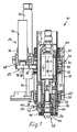
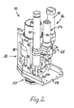
- the drill 10 includes a spindle unit 20 and an eccentric rotation mechanism 22 in the nature of an orbital drive unit 24 secured in a frame or housing 26 of the drill 10.
- the housing 26 includes a bottom plate 28 and a top 30 interconnected by a wall member 18.
- the spindle unit 20 includes a spindle motor 32 and a radial offset mechanism 34.
- the radial offset mechanism 34 basically comprises, in a manner known per se, an inner sleeve 36 rotatably supporting the spindle unit 20 therein.
- the spindle motor 32 is rotatably supported in an eccentric cylindrical hole in the inner sleeve 36.
- the eccentric hole has a longitudinal center axis that is parallel to but radially offset from the longitudinal center axis of the sleeve 36.
- the eccentric inner sleeve 36 is, in its turn, rotatably supported within an axially extending eccentric hole of an outer sleeve 38.
- the latter eccentric hole has a longitudinal center axis that is parallel to but radially offset from the center axis of the sleeve 36 (the principal axis).
- the holes of the sleeves 36 and 38 have the same eccentricity, i.e. the hole center axes are radially offset the same distance from the respective center axis of the sleeves 36 and 38.
- the inner sleeve 36 By rotating the inner sleeve 36 within the eccentric hole of the outer sleeve 38, or by a mutual, relative rotation of the sleeves 36 and 38, it is thus possible to locate the center axis of the eccentric hole of the inner sleeve 36 such that it, and hence the spindle unit 20 and the center axis of the cutting tool (not shown) fixed thereto, will coincide with the center axis of the outer sleeve 38. In this case there is no radial offset at all of the cutting tool axis.
- a maximum offset of the cutting tool axis is obtained.
- the adjustment of the radial offset of the cutting tool axis relative to the principal axis (the axis of the hole to be formed) may be achieved by rotating a set screw 40 located tangentially between the inner and outer sleeves.
- a locking ring 42, an axial nut 44 and a zero point ring 46 are provided at a front end 48 of the spindle unit 20, and a motor cover 50 is provided at a back end 52 of the spindle unit 20 and is secured to the inner sleeve 36.
- a spindle shaft 54 is operatively connected to and driven by the spindle motor 32 through a clutch coupling 56.
- the spindle shaft 54 is mounted in the inner sleeve 36 by needle bearings 58 and spindle bearings 60.
- a tool holder (not shown) for holding a cutting tool (not shown) is mounted to the spindle shaft 54.
- the spindle unit 20 is mounted in the housing 26 by a bushing 62 between the outer sleeve 38 and the bottom plate 28, and by a bushing 64 between the outer sleeve 38 and top 30.
- a forward guide 66 extending forwardly from bottom plate 28 provides added stability and positioning for spindle unit 20 relative to bottom plate 28.
- the spindle unit 20 is further mounted to a carrier 68 by bearings 70 and 72.
- the carrier 68 is axially adjustable in the housing 26, as will be described subsequently.
- the orbital drive unit 24 includes a motor 74 secured in a motor bracket 76 on the carrier 68.
- a pulley 78 is mounted on a shaft 80 of the motor 74.
- a drive belt 82 establishes a driving connection between pulley 78 and the outer sleeve 38, through a pulley surface 84 formed integrally on outer sleeve 38.
- the orbit motor 74 thereby rotates spindle unit 20, with carrier 68 held rotationally stationary, together with the housing 26.
- An axial feed mechanism 86 operates on the spindle unit 20 and the orbital drive unit 24 to adjust the axial positions thereof in the housing 26 between a fully advanced position ( Fig. 4 ) and a fully retracted position ( Fig. 3 ), as will be described hereinafter.
- the axial feed mechanism 86 establishes an axially adjustable interconnection between housing 26 and carrier 68, and thereby the components carried by carrier 68, including the spindle unit 20 and the orbital drive unit 24.
- the axial feed mechanism 86 comprises an axial adjustment cylinder 88 mounted on the top 30 of housing 26 and including a cylinder rod 90 connected to the carrier 68.
- the axial adjustment cylinder 88 is preferably a double acting pneumatic cylinder effecting axial movement of the carrier 68 both forwardly and backwardly.
- An hydraulic damping cylinder 92 is mounted on carrier 68, and includes a cylinder rod 94 biased against or connected to the bottom plate 28 for accurately controlling the speed of the advancing movement of the carrier 68 and the spindle unit 20 caused by the pneumatic cylinder 88 towards a workpiece (not shown).
- the damping cylinder 92 includes adjustable valve means (not shown) for adjusting the speed of advancement of the spindle unit 20.
- Figs. 1 , 2 and 3 show the spindle unit 20 in its axially retracted position.
- the carrier 68 is near the top 30, with the cylinder rod 90 retracted within the axial adjustment cylinder 88.
- the cylinder rod 94 of the damping cylinder 90 is extended and engages the bottom plate 28.
- the cylinder rod 90 is extended from the axial adjustment cylinder 88 while simultaneously cylinder rod 94 is retracted into the damping cylinder 90 in a controlled manner.
- the carrier 68 is thereby advanced toward the bottom plate 28 and away from the top 30.
- An extended position of spindle unit 20 is illustrated in Figs. 4 .
- the spindle unit 20 and the orbital drive unit 24 are both mounted to the carrier 68, both are axially adjusted together, and the driving connection between the orbit motor 74 and the spindle unit 20 is maintained.
- the driving connection between the orbit motor 74 and the spindle unit 20 can be a fixed, stable connection, not requiring either or both to allow and compensate for movement by the other or both.
Landscapes
- Engineering & Computer Science (AREA)
- Mechanical Engineering (AREA)
- Drilling And Boring (AREA)
- Automatic Tool Replacement In Machine Tools (AREA)
- Machine Tool Units (AREA)
- Drilling Tools (AREA)
- Milling Processes (AREA)
Claims (9)
- Handwerkzeugvorrichtung zur Verwendung eines Schneidewerkzeugs mit einer ersten Breite und einer Werkzeugachse um ein Loch aus einem Objekt herauszuarbeiten, wobei das mit dem Schneidwerkzeug zu formende Loch eine zweite Breite aufweist die größer ist als die erste Breite des Schneidwerkzeuges, die Vorrichtung umfasst:ein Gehäuse (26), gekennzeichnet durcheinen Träger (68) angeordnet an und axial beweglich relativ zu dem Gehäuse (26);
eine Spindeleinheit (20) mit einer Hauptachse und umfassend einen Spindelmotor (32), eine Spindelwelle (54) zum Drehen des Schneidwerkzeuges, und einen radialen Korrekturmechanismus (34) ausgebildet zum Einstellen einer Radialkorrektur der Schneidewerkzeugachse relativ zu der Hauptachse, die Spindeleinheit (20) ist an dem Träger (68) gegen axiale Bewegung gesichert während sie relativ zu dem Träger (68) um die Hauptachse drehbar ist;
einen Orbitalantriebsmotor (74), der auf dem Träger (68) angeordnet ist und der antreibbar mit der Spindeleinheit (20) zum Drehen der Spindeleinheit um die Hauptachse relativ zu dem Träger verbunden ist; und
einen axialer Fördermechanismus (86), der an dem Gehäuse (26) und dem Träger (68) befestigt ist und der zum verbundenen Voranführen und Herausziehen der Spindeleinheit (20) gemeinsam mit dem Träger (68) und dem Orbitalantriebsmotor (74) relativ zu dem Objekt angeordnet ist. - Handwerkzeugvorrichtung nach Anspruch 1, bei der der axiale Fördermechanismus einen axialen Einstellzylinder (88) mit einer Zylinderstange (90) umfasst, wobei der Zylinder mit dem Gehäuse (26) oder dem Träger (68) verbunden ist, wohingegen die Zylinderstange (90) mit dem jeweils Anderen dem Gehäuse oder dem Träger verbunden ist.
- Handwerkzeugvorrichtung nach Anspruch 2, bei der der axiale Einstellzylinder (88) einen Pneumatikzylinder umfasst.
- Handwerkzeugvorrichtung nach Anspruch 3, bei der ein hydraulischer Dämpfungszylinder (92) an dem Träger (68) befestigt ist und eine Zylinderstange (94) aufweist, die von dem Gehäuse (26) beabstandet ist.
- Handwerkzeugvorrichtung nach Anspruch 4, bei der der hydraulische Dämpfungszylinder ausgebildet ist, um einstellbar die von dem Pneumatikzylinder (88) verursachte Vorführgeschwindigkeit des Trägers (68) zu steuern.
- Handwerkzeugvorrichtung nach einem der Ansprüche 1-5, bei der das Gehäuse (26) eine Deckplatte (30) und eine Bodenplatte (28) umfasst, wobei der Träger (68) mittels des axialen Einstellzylinders (88) axial zwischen der Deckplatte und der Bodenplatte beweglich ist.
- Handwerkzeugvorrichtung nach einem der Ansprüche 1-6, bei der der radiale Korrekturmechanismus (34) eine innere Hülse (36) und eine äußere Hülse (38) umfasst, die inneren und äußere Hülse (36, 38) sind mittels einer Einstellschraube (40) relativ zueinander drehbar, wobei der Spindelmotor (32) an der inneren Hülse (36) befestigt ist und die Spindelwelle (54) in der inneren Hülse (36) drehbar ist.
- Handwerkzeugvorrichtung nach Anspruch 7, bei der die äußere Hülse (38) in der Deckplatte (30), in dem Träger (68) und in der Bodenplatte (28) um eine Hauptachse drehbar ist.
- Handwerkzeugvorrichtung nach einem der Ansprüche 1-8, bei der der Orbitalantriebsmotor (74) eine Motorwelle (80) und eine von ihr angetriebene Riemenscheibe (78) aufweist, und ein Riemen (82) antreibend die Riemenscheibe mit der Spindeleinheit verbindet.
Applications Claiming Priority (3)
| Application Number | Priority Date | Filing Date | Title |
|---|---|---|---|
| US103623 | 1987-10-01 | ||
| US10/103,623 US6719505B2 (en) | 1999-09-01 | 2002-03-21 | Orbital hand tool apparatus for drilling |
| PCT/SE2003/000467 WO2003080277A1 (en) | 2002-03-21 | 2003-03-20 | Orbital hand tool apparatus for drilling |
Publications (2)
| Publication Number | Publication Date |
|---|---|
| EP1490193A1 EP1490193A1 (de) | 2004-12-29 |
| EP1490193B1 true EP1490193B1 (de) | 2009-06-17 |
Family
ID=28452373
Family Applications (1)
| Application Number | Title | Priority Date | Filing Date |
|---|---|---|---|
| EP03745054A Expired - Lifetime EP1490193B1 (de) | 2002-03-21 | 2003-03-20 | Handwerkzeug zum bohren auf kreisförmiger bahn |
Country Status (9)
| Country | Link |
|---|---|
| US (2) | US6719505B2 (de) |
| EP (1) | EP1490193B1 (de) |
| JP (1) | JP2005520696A (de) |
| CN (1) | CN100341651C (de) |
| AT (1) | ATE433816T1 (de) |
| AU (1) | AU2003255292B2 (de) |
| DE (1) | DE60328000D1 (de) |
| ES (1) | ES2328569T3 (de) |
| WO (1) | WO2003080277A1 (de) |
Families Citing this family (31)
| Publication number | Priority date | Publication date | Assignee | Title |
|---|---|---|---|---|
| DE602004025109D1 (de) * | 2003-06-26 | 2010-03-04 | Novator Ab | Gerät für die umlaufbahnartige bearbeitung mit antriebselement mit antriebsstiften |
| FR2869557B1 (fr) * | 2004-04-29 | 2006-07-07 | Bosch Gmbh Robert | Dispositif d'usinage de rainures dans un alesage cylindrique en particulier d'un maitre-cylindre de frein |
| US20070248426A1 (en) * | 2004-06-09 | 2007-10-25 | Bjorn Pettersson | Device for Fixating a Portable Drilling Machine in Guide Holes in a Template |
| US20060269369A1 (en) * | 2005-05-24 | 2006-11-30 | The Boeing Company | Portable electro-pneumatic drill apparatus |
| US7627940B2 (en) * | 2005-07-13 | 2009-12-08 | The Boeing Company | Orbital hole match drilling |
| US7614159B2 (en) * | 2006-08-23 | 2009-11-10 | The Boeing Company | Locating and drilling determinate assembly holes using a coordinate measuring device |
| CN100453224C (zh) * | 2007-03-13 | 2009-01-21 | 重庆建设摩托车股份有限公司 | 孔内凹腔螺旋面的手动铣削装置 |
| ES2622144T3 (es) * | 2007-05-18 | 2017-07-05 | Hukuzo Yagishita | Dispositivo de perforación y método para producir un objeto perforado |
| WO2009005446A1 (en) * | 2007-07-05 | 2009-01-08 | Novator Ab | An orbital drilling tool unit |
| US7611314B2 (en) * | 2007-08-01 | 2009-11-03 | The Boeing Company | Aligning a machine tool with a target location on a structure |
| ITBO20080368A1 (it) * | 2008-06-10 | 2009-12-11 | Teseo Spa | Dispositivo per la movimentazione di utensili per la recisione di articoli piani, in particolare pelli |
| CN102131469B (zh) | 2008-06-26 | 2013-07-17 | W·安德森 | 深度可控且可测的医疗驱动设备及使用方法 |
| GB2472448A (en) * | 2009-08-07 | 2011-02-09 | Univ Sheffield | Compact Machine Tool with Secure Mount to Workpiece |
| EP2529867A1 (de) * | 2010-01-29 | 2012-12-05 | Hukuzo Yagisita | Bohrvorrichtung |
| US8894654B2 (en) * | 2010-03-31 | 2014-11-25 | Smart Medical Devices, Inc. | Depth controllable and measurable medical driver devices and methods of use |
| WO2011140154A2 (en) * | 2010-05-03 | 2011-11-10 | National Oilwell Varco, L.P. | Cutting device on moveable platform |
| US8602698B2 (en) | 2010-08-25 | 2013-12-10 | Kennametal Inc. | Combination end milling/drilling/reaming cutting tool |
| US9393669B2 (en) | 2011-10-21 | 2016-07-19 | Strasbaugh | Systems and methods of processing substrates |
| US9457446B2 (en) | 2012-10-01 | 2016-10-04 | Strasbaugh | Methods and systems for use in grind shape control adaptation |
| US9610669B2 (en) * | 2012-10-01 | 2017-04-04 | Strasbaugh | Methods and systems for use in grind spindle alignment |
| CN103128354B (zh) * | 2013-01-31 | 2015-03-11 | 南京航空航天大学 | 应用偏心调节机构的手持式螺旋铣孔装置与螺旋铣孔方法 |
| CN103252519B (zh) * | 2013-05-02 | 2016-09-21 | 台州市盛业设备制造有限公司 | 两种孔径定位加工机构 |
| WO2015124990A1 (en) * | 2014-02-18 | 2015-08-27 | Pedrini Spa Ad Unico Socio | Improved mandrel for sizing, smoothing or polishing stone materials with rotating abrasive heads |
| WO2017139674A1 (en) | 2016-02-12 | 2017-08-17 | Smart Medical Devices, Inc. | Driving devices and methods for determining material strength in real-time |
| CN107953003B (zh) * | 2018-01-17 | 2019-01-25 | 南京信息职业技术学院 | 电机串列式独立进给螺旋铣削装置 |
| CN111482638B (zh) * | 2020-04-20 | 2021-09-28 | 大连理工大学 | 一种便携式螺旋铣孔单元 |
| CN111482639B (zh) * | 2020-04-20 | 2021-09-24 | 大连理工大学 | 一种螺旋铣孔装置的传动机构 |
| CN111482641B (zh) * | 2020-04-20 | 2021-06-22 | 大连理工大学 | 一种螺旋铣孔的偏心调节方法 |
| EP4140625A4 (de) * | 2020-04-20 | 2023-06-07 | Dalian University Of Technology | Tragbare spiralfräseinheit und exzentrizitätseinstellungsverfahren |
| CN111482640B (zh) * | 2020-04-20 | 2021-09-28 | 大连理工大学 | 一种大直径交点孔便携式螺旋铣孔单元 |
| IT202300023589A1 (it) * | 2023-11-09 | 2025-05-09 | Walter Tosto S P A | Smerigliatrice assiale orbitale per bocchelli |
Family Cites Families (34)
| Publication number | Priority date | Publication date | Assignee | Title |
|---|---|---|---|---|
| US2648939A (en) | 1947-10-18 | 1953-08-18 | Vulcan Tool Company | Pneumatic grinder |
| US2742796A (en) | 1953-04-24 | 1956-04-24 | Ervin Hodson Jr | Adjustable gearing |
| US2922323A (en) * | 1953-06-18 | 1960-01-26 | Air Prod Inc | Automatic high speed deep hole drilling machine |
| BE549128A (de) | 1955-07-12 | |||
| US2863339A (en) * | 1956-01-26 | 1958-12-09 | Dorothea A Emrick | Hydraulic air drilling unit |
| US3024671A (en) * | 1958-11-03 | 1962-03-13 | Madonna Anthony Joseph | Automatic drilling appliance feeding attachment |
| US3039329A (en) * | 1960-04-18 | 1962-06-19 | Snyder Corp | Drill press |
| US3119210A (en) | 1961-08-08 | 1964-01-28 | Roland E Doeden | Air operated tool |
| US3333488A (en) * | 1965-01-18 | 1967-08-01 | Wallace Supplies Mfg Company | Annular drilling machine |
| DE1273303B (de) | 1967-03-25 | 1968-07-18 | Maschf Augsburg Nuernberg Ag | Fraeseinrichtung |
| US3533195A (en) | 1968-04-22 | 1970-10-13 | Rockwell Mfg Co | Jig grinder head |
| US3540347A (en) | 1968-08-15 | 1970-11-17 | Joseph Gerard Randall | Method and apparatus for machining workpieces |
| US3613222A (en) | 1969-06-23 | 1971-10-19 | Owens Illinois Inc | Method for making a lightweight optical mirror |
| US3803981A (en) | 1972-01-17 | 1974-04-16 | Owens Illinois Inc | Independent drive sub-spindle mounted for eccentric adjustment in prime spindle |
| DE2542679C3 (de) | 1975-09-25 | 1978-11-30 | Werkzeugfabrik J.C. & Alb. Zenses, 5630 Remscheid | Vorsatzgerät für Handbohrmaschinen |
| US4025218A (en) * | 1975-11-10 | 1977-05-24 | Camco, Incorporated | Drilling machine |
| DE3238442C2 (de) * | 1982-10-16 | 1984-11-15 | Krones Ag Hermann Kronseder Maschinenfabrik, 8402 Neutraubling | Fräsvorrichtung zum Erzeugen von Polygonprofilen |
| DE3246548C2 (de) | 1982-12-16 | 1987-04-02 | Danfoss A/S, Nordborg | Druckmittelbetätigtes Bohrgerät |
| US4594030A (en) * | 1984-01-30 | 1986-06-10 | The Boeing Company | Pneumatic-hydraulic drill unit |
| US4869626A (en) * | 1986-04-18 | 1989-09-26 | Dynamotion Corporation | High speed drilling spindle |
| US4934040A (en) | 1986-07-10 | 1990-06-19 | Turchan Manuel C | Spindle driver for machine tools |
| BR8801488A (pt) | 1987-09-17 | 1989-03-21 | Gte Valenite Corp | Ferramenta para maquina controlada numericamente para usinar um furo numa peca de trabalho |
| JP2879151B2 (ja) | 1989-07-04 | 1999-04-05 | 富士精工株式会社 | 刃先位置変更可能な切削加工装置 |
| AT395835B (de) * | 1990-03-29 | 1993-03-25 | Weingartner Maschbau Gmbh | Verfahren zum herstellen einer parallelachsigen rotationskolbenmaschine |
| US5073068A (en) | 1990-05-24 | 1991-12-17 | Doler Inc. | Peck feed drilling machine |
| DE4210898A1 (de) * | 1992-04-02 | 1993-10-07 | Grob Gmbh & Co Kg | Werkzeugspindel, insbesondere Bohrspindel |
| EP0571352B1 (de) | 1992-05-14 | 1997-10-01 | Sandvik Aktiebolag | Verfahren zum Bearbeiten von Verbundwerkstoffen |
| SE9203493L (sv) | 1992-11-19 | 1994-05-20 | Strukturteknologier I Stockhol | Metod för håltagning i fiberarmerade kompositmaterial och verktyg för genomförande av metoden |
| SE9300400L (sv) | 1993-02-05 | 1994-08-06 | Strukturteknologier I Stockhol | Verktygsmaskin för upptagning av en genomgående öppning i ett föremål av fiberkomposit |
| FR2720308B1 (fr) | 1994-05-31 | 1996-08-09 | Recoules Fils Ets | Machine pneumatique d'usinage. |
| US5921731A (en) * | 1996-12-31 | 1999-07-13 | The Ingersoll Milling Machine Company | High speed hydrostatic spindle |
| US5971678A (en) | 1998-06-05 | 1999-10-26 | Novator Ab | Spindle unit |
| US6382890B1 (en) * | 1999-09-01 | 2002-05-07 | Novator Ab | Hand tool apparatus for orbital drilling |
| EP1417067B1 (de) * | 2001-07-20 | 2010-11-24 | Novator AB | Numerisch gesteuerte umlaufbahnbearbeitungsvorrichtung |
-
2002
- 2002-03-21 US US10/103,623 patent/US6719505B2/en not_active Expired - Fee Related
-
2003
- 2003-01-15 US US10/345,017 patent/US6758642B2/en not_active Expired - Fee Related
- 2003-03-20 AT AT03745054T patent/ATE433816T1/de not_active IP Right Cessation
- 2003-03-20 EP EP03745054A patent/EP1490193B1/de not_active Expired - Lifetime
- 2003-03-20 WO PCT/SE2003/000467 patent/WO2003080277A1/en not_active Ceased
- 2003-03-20 DE DE60328000T patent/DE60328000D1/de not_active Expired - Fee Related
- 2003-03-20 ES ES03745054T patent/ES2328569T3/es not_active Expired - Lifetime
- 2003-03-20 JP JP2003578090A patent/JP2005520696A/ja not_active Withdrawn
- 2003-03-20 AU AU2003255292A patent/AU2003255292B2/en not_active Ceased
- 2003-03-20 CN CNB038066025A patent/CN100341651C/zh not_active Expired - Fee Related
Also Published As
| Publication number | Publication date |
|---|---|
| AU2003255292B2 (en) | 2008-03-20 |
| CN1688405A (zh) | 2005-10-26 |
| JP2005520696A (ja) | 2005-07-14 |
| EP1490193A1 (de) | 2004-12-29 |
| US20030113181A1 (en) | 2003-06-19 |
| ES2328569T3 (es) | 2009-11-16 |
| CN100341651C (zh) | 2007-10-10 |
| AU2003255292A1 (en) | 2003-10-08 |
| DE60328000D1 (de) | 2009-07-30 |
| US6719505B2 (en) | 2004-04-13 |
| ATE433816T1 (de) | 2009-07-15 |
| US6758642B2 (en) | 2004-07-06 |
| WO2003080277A1 (en) | 2003-10-02 |
| US20020102144A1 (en) | 2002-08-01 |
Similar Documents
| Publication | Publication Date | Title |
|---|---|---|
| EP1490193B1 (de) | Handwerkzeug zum bohren auf kreisförmiger bahn | |
| EP1806194B1 (de) | Handwerkzeug zum orbitalen Bohren | |
| US20100183395A1 (en) | Orbital drilling tool unit | |
| US4622871A (en) | Cutting tool compensator for stationary machine tool | |
| EP2248619A1 (de) | Orbitalbearbeitungsvorrichtung zur Herstellung von Löchern und Radialoffset-Mechanismus für eine solche Vorrichtung | |
| CN102892538A (zh) | 钻孔加工装置 | |
| JPS5813282B2 (ja) | 中ぐりヘッド | |
| KR19980702688A (ko) | 공구용 위치 설정 장치 및 위치 설정 구동부를 포함한 공구헤드 | |
| EP1102653A1 (de) | Spindeleinheit zum herstellen eines lochs in einem werkstück aus faserverstärktem material | |
| KR20160116473A (ko) | 심공드릴링머신용 유압식 회전지그장치 | |
| EP1635975B1 (de) | Gerät für die umlaufbahnartige bearbeitung mit antriebselement mit antriebsstiften | |
| JPH0335906A (ja) | 刃先位置変更可能な切削加工装置 | |
| JPH10151501A (ja) | 旋盤用偏心・楕円軸加工アタッチメント | |
| KR102578108B1 (ko) | 절삭 공구 및 조절 장치가 장착된 절삭 공구를 위한 조절 장치 | |
| EP0345344A4 (en) | Airfeed peck drill configuration | |
| WO2016209145A1 (en) | Orbital machine, method, computer program and a computer program product for using said machine | |
| JPH0694086B2 (ja) | 主軸摺動型自動旋盤 | |
| JPH0611909U (ja) | 主軸貫通孔仕様ドリルユニット | |
| HK1022282A1 (en) | Tool head for use in machine tools | |
| HK1022282B (en) | Tool head for use in machine tools |
Legal Events
| Date | Code | Title | Description |
|---|---|---|---|
| PUAI | Public reference made under article 153(3) epc to a published international application that has entered the european phase |
Free format text: ORIGINAL CODE: 0009012 |
|
| 17P | Request for examination filed |
Effective date: 20040928 |
|
| AK | Designated contracting states |
Kind code of ref document: A1 Designated state(s): AT BE BG CH CY CZ DE DK EE ES FI FR GB GR HU IE IT LI LU MC NL PT RO SE SI SK TR |
|
| AX | Request for extension of the european patent |
Extension state: AL LT LV MK |
|
| GRAP | Despatch of communication of intention to grant a patent |
Free format text: ORIGINAL CODE: EPIDOSNIGR1 |
|
| RIC1 | Information provided on ipc code assigned before grant |
Ipc: B23C 1/20 20060101ALI20090217BHEP Ipc: B23B 45/00 20060101AFI20090217BHEP |
|
| GRAS | Grant fee paid |
Free format text: ORIGINAL CODE: EPIDOSNIGR3 |
|
| GRAA | (expected) grant |
Free format text: ORIGINAL CODE: 0009210 |
|
| AK | Designated contracting states |
Kind code of ref document: B1 Designated state(s): AT BE BG CH CY CZ DE DK EE ES FI FR GB GR HU IE IT LI LU MC NL PT RO SE SI SK TR |
|
| REG | Reference to a national code |
Ref country code: GB Ref legal event code: FG4D |
|
| REG | Reference to a national code |
Ref country code: CH Ref legal event code: EP |
|
| REG | Reference to a national code |
Ref country code: IE Ref legal event code: FG4D |
|
| REF | Corresponds to: |
Ref document number: 60328000 Country of ref document: DE Date of ref document: 20090730 Kind code of ref document: P |
|
| PG25 | Lapsed in a contracting state [announced via postgrant information from national office to epo] |
Ref country code: AT Free format text: LAPSE BECAUSE OF FAILURE TO SUBMIT A TRANSLATION OF THE DESCRIPTION OR TO PAY THE FEE WITHIN THE PRESCRIBED TIME-LIMIT Effective date: 20090617 Ref country code: FI Free format text: LAPSE BECAUSE OF FAILURE TO SUBMIT A TRANSLATION OF THE DESCRIPTION OR TO PAY THE FEE WITHIN THE PRESCRIBED TIME-LIMIT Effective date: 20090617 |
|
| REG | Reference to a national code |
Ref country code: ES Ref legal event code: FG2A Ref document number: 2328569 Country of ref document: ES Kind code of ref document: T3 |
|
| PG25 | Lapsed in a contracting state [announced via postgrant information from national office to epo] |
Ref country code: SI Free format text: LAPSE BECAUSE OF FAILURE TO SUBMIT A TRANSLATION OF THE DESCRIPTION OR TO PAY THE FEE WITHIN THE PRESCRIBED TIME-LIMIT Effective date: 20090617 Ref country code: SE Free format text: LAPSE BECAUSE OF FAILURE TO SUBMIT A TRANSLATION OF THE DESCRIPTION OR TO PAY THE FEE WITHIN THE PRESCRIBED TIME-LIMIT Effective date: 20090917 |
|
| NLV1 | Nl: lapsed or annulled due to failure to fulfill the requirements of art. 29p and 29m of the patents act | ||
| PG25 | Lapsed in a contracting state [announced via postgrant information from national office to epo] |
Ref country code: CZ Free format text: LAPSE BECAUSE OF FAILURE TO SUBMIT A TRANSLATION OF THE DESCRIPTION OR TO PAY THE FEE WITHIN THE PRESCRIBED TIME-LIMIT Effective date: 20090617 Ref country code: EE Free format text: LAPSE BECAUSE OF FAILURE TO SUBMIT A TRANSLATION OF THE DESCRIPTION OR TO PAY THE FEE WITHIN THE PRESCRIBED TIME-LIMIT Effective date: 20090617 Ref country code: RO Free format text: LAPSE BECAUSE OF FAILURE TO SUBMIT A TRANSLATION OF THE DESCRIPTION OR TO PAY THE FEE WITHIN THE PRESCRIBED TIME-LIMIT Effective date: 20090617 |
|
| PG25 | Lapsed in a contracting state [announced via postgrant information from national office to epo] |
Ref country code: NL Free format text: LAPSE BECAUSE OF FAILURE TO SUBMIT A TRANSLATION OF THE DESCRIPTION OR TO PAY THE FEE WITHIN THE PRESCRIBED TIME-LIMIT Effective date: 20090617 Ref country code: BE Free format text: LAPSE BECAUSE OF FAILURE TO SUBMIT A TRANSLATION OF THE DESCRIPTION OR TO PAY THE FEE WITHIN THE PRESCRIBED TIME-LIMIT Effective date: 20090617 Ref country code: SK Free format text: LAPSE BECAUSE OF FAILURE TO SUBMIT A TRANSLATION OF THE DESCRIPTION OR TO PAY THE FEE WITHIN THE PRESCRIBED TIME-LIMIT Effective date: 20090617 |
|
| PG25 | Lapsed in a contracting state [announced via postgrant information from national office to epo] |
Ref country code: BG Free format text: LAPSE BECAUSE OF FAILURE TO SUBMIT A TRANSLATION OF THE DESCRIPTION OR TO PAY THE FEE WITHIN THE PRESCRIBED TIME-LIMIT Effective date: 20090917 Ref country code: PT Free format text: LAPSE BECAUSE OF FAILURE TO SUBMIT A TRANSLATION OF THE DESCRIPTION OR TO PAY THE FEE WITHIN THE PRESCRIBED TIME-LIMIT Effective date: 20091017 |
|
| PLBE | No opposition filed within time limit |
Free format text: ORIGINAL CODE: 0009261 |
|
| STAA | Information on the status of an ep patent application or granted ep patent |
Free format text: STATUS: NO OPPOSITION FILED WITHIN TIME LIMIT |
|
| PG25 | Lapsed in a contracting state [announced via postgrant information from national office to epo] |
Ref country code: DK Free format text: LAPSE BECAUSE OF FAILURE TO SUBMIT A TRANSLATION OF THE DESCRIPTION OR TO PAY THE FEE WITHIN THE PRESCRIBED TIME-LIMIT Effective date: 20090617 |
|
| 26N | No opposition filed |
Effective date: 20100318 |
|
| PG25 | Lapsed in a contracting state [announced via postgrant information from national office to epo] |
Ref country code: MC Free format text: LAPSE BECAUSE OF NON-PAYMENT OF DUE FEES Effective date: 20100331 Ref country code: GR Free format text: LAPSE BECAUSE OF FAILURE TO SUBMIT A TRANSLATION OF THE DESCRIPTION OR TO PAY THE FEE WITHIN THE PRESCRIBED TIME-LIMIT Effective date: 20090918 |
|
| REG | Reference to a national code |
Ref country code: CH Ref legal event code: PL |
|
| GBPC | Gb: european patent ceased through non-payment of renewal fee |
Effective date: 20100320 |
|
| REG | Reference to a national code |
Ref country code: FR Ref legal event code: ST Effective date: 20101130 |
|
| PG25 | Lapsed in a contracting state [announced via postgrant information from national office to epo] |
Ref country code: IE Free format text: LAPSE BECAUSE OF NON-PAYMENT OF DUE FEES Effective date: 20100320 Ref country code: FR Free format text: LAPSE BECAUSE OF NON-PAYMENT OF DUE FEES Effective date: 20100331 |
|
| PG25 | Lapsed in a contracting state [announced via postgrant information from national office to epo] |
Ref country code: CH Free format text: LAPSE BECAUSE OF NON-PAYMENT OF DUE FEES Effective date: 20100331 Ref country code: DE Free format text: LAPSE BECAUSE OF NON-PAYMENT OF DUE FEES Effective date: 20101001 Ref country code: LI Free format text: LAPSE BECAUSE OF NON-PAYMENT OF DUE FEES Effective date: 20100331 |
|
| PG25 | Lapsed in a contracting state [announced via postgrant information from national office to epo] |
Ref country code: IT Free format text: LAPSE BECAUSE OF NON-PAYMENT OF DUE FEES Effective date: 20100320 Ref country code: GB Free format text: LAPSE BECAUSE OF NON-PAYMENT OF DUE FEES Effective date: 20100320 |
|
| REG | Reference to a national code |
Ref country code: ES Ref legal event code: FD2A Effective date: 20110415 |
|
| PG25 | Lapsed in a contracting state [announced via postgrant information from national office to epo] |
Ref country code: ES Free format text: LAPSE BECAUSE OF NON-PAYMENT OF DUE FEES Effective date: 20110404 |
|
| PG25 | Lapsed in a contracting state [announced via postgrant information from national office to epo] |
Ref country code: ES Free format text: LAPSE BECAUSE OF NON-PAYMENT OF DUE FEES Effective date: 20100321 |
|
| PG25 | Lapsed in a contracting state [announced via postgrant information from national office to epo] |
Ref country code: CY Free format text: LAPSE BECAUSE OF FAILURE TO SUBMIT A TRANSLATION OF THE DESCRIPTION OR TO PAY THE FEE WITHIN THE PRESCRIBED TIME-LIMIT Effective date: 20090617 |
|
| PG25 | Lapsed in a contracting state [announced via postgrant information from national office to epo] |
Ref country code: LU Free format text: LAPSE BECAUSE OF NON-PAYMENT OF DUE FEES Effective date: 20100320 Ref country code: HU Free format text: LAPSE BECAUSE OF FAILURE TO SUBMIT A TRANSLATION OF THE DESCRIPTION OR TO PAY THE FEE WITHIN THE PRESCRIBED TIME-LIMIT Effective date: 20091218 |
|
| PG25 | Lapsed in a contracting state [announced via postgrant information from national office to epo] |
Ref country code: TR Free format text: LAPSE BECAUSE OF FAILURE TO SUBMIT A TRANSLATION OF THE DESCRIPTION OR TO PAY THE FEE WITHIN THE PRESCRIBED TIME-LIMIT Effective date: 20090617 |