EP1490596B1 - Dispositif de demarrage pour moteur a combustion interne et procede de demarrage d'un moteur a combustion interne - Google Patents
Dispositif de demarrage pour moteur a combustion interne et procede de demarrage d'un moteur a combustion interne Download PDFInfo
- Publication number
- EP1490596B1 EP1490596B1 EP03714645A EP03714645A EP1490596B1 EP 1490596 B1 EP1490596 B1 EP 1490596B1 EP 03714645 A EP03714645 A EP 03714645A EP 03714645 A EP03714645 A EP 03714645A EP 1490596 B1 EP1490596 B1 EP 1490596B1
- Authority
- EP
- European Patent Office
- Prior art keywords
- switching
- enable
- internal combustion
- enable signal
- combustion engine
- Prior art date
- Legal status (The legal status is an assumption and is not a legal conclusion. Google has not performed a legal analysis and makes no representation as to the accuracy of the status listed.)
- Expired - Lifetime
Links
- 238000002485 combustion reaction Methods 0.000 title claims description 60
- 239000007858 starting material Substances 0.000 title claims description 37
- 238000000034 method Methods 0.000 title claims description 29
- 230000009849 deactivation Effects 0.000 claims description 32
- 230000005540 biological transmission Effects 0.000 claims description 27
- 230000004913 activation Effects 0.000 claims description 17
- 230000000977 initiatory effect Effects 0.000 claims description 2
- 230000004907 flux Effects 0.000 claims 2
- 230000000694 effects Effects 0.000 claims 1
- 230000006870 function Effects 0.000 description 9
- 238000003745 diagnosis Methods 0.000 description 7
- 230000008569 process Effects 0.000 description 7
- 239000003990 capacitor Substances 0.000 description 4
- 238000001514 detection method Methods 0.000 description 3
- 230000007257 malfunction Effects 0.000 description 3
- 230000001419 dependent effect Effects 0.000 description 2
- 238000013461 design Methods 0.000 description 2
- 230000007935 neutral effect Effects 0.000 description 2
- 230000006399 behavior Effects 0.000 description 1
- 230000000903 blocking effect Effects 0.000 description 1
- 230000008859 change Effects 0.000 description 1
- 238000013479 data entry Methods 0.000 description 1
- 238000010586 diagram Methods 0.000 description 1
- 230000002045 lasting effect Effects 0.000 description 1
- 238000012423 maintenance Methods 0.000 description 1
- 230000007246 mechanism Effects 0.000 description 1
- 238000012552 review Methods 0.000 description 1
- 238000013519 translation Methods 0.000 description 1
- 238000013024 troubleshooting Methods 0.000 description 1
Images

Classifications
-
- F—MECHANICAL ENGINEERING; LIGHTING; HEATING; WEAPONS; BLASTING
- F02—COMBUSTION ENGINES; HOT-GAS OR COMBUSTION-PRODUCT ENGINE PLANTS
- F02N—STARTING OF COMBUSTION ENGINES; STARTING AIDS FOR SUCH ENGINES, NOT OTHERWISE PROVIDED FOR
- F02N11/00—Starting of engines by means of electric motors
- F02N11/10—Safety devices
- F02N11/101—Safety devices for preventing engine starter actuation or engagement
- F02N11/103—Safety devices for preventing engine starter actuation or engagement according to the vehicle transmission or clutch status
-
- B—PERFORMING OPERATIONS; TRANSPORTING
- B60—VEHICLES IN GENERAL
- B60K—ARRANGEMENT OR MOUNTING OF PROPULSION UNITS OR OF TRANSMISSIONS IN VEHICLES; ARRANGEMENT OR MOUNTING OF PLURAL DIVERSE PRIME-MOVERS IN VEHICLES; AUXILIARY DRIVES FOR VEHICLES; INSTRUMENTATION OR DASHBOARDS FOR VEHICLES; ARRANGEMENTS IN CONNECTION WITH COOLING, AIR INTAKE, GAS EXHAUST OR FUEL SUPPLY OF PROPULSION UNITS IN VEHICLES
- B60K28/00—Safety devices for propulsion-unit control, specially adapted for, or arranged in, vehicles, e.g. preventing fuel supply or ignition in the event of potentially dangerous conditions
- B60K28/10—Safety devices for propulsion-unit control, specially adapted for, or arranged in, vehicles, e.g. preventing fuel supply or ignition in the event of potentially dangerous conditions responsive to conditions relating to the vehicle
-
- F—MECHANICAL ENGINEERING; LIGHTING; HEATING; WEAPONS; BLASTING
- F02—COMBUSTION ENGINES; HOT-GAS OR COMBUSTION-PRODUCT ENGINE PLANTS
- F02N—STARTING OF COMBUSTION ENGINES; STARTING AIDS FOR SUCH ENGINES, NOT OTHERWISE PROVIDED FOR
- F02N11/00—Starting of engines by means of electric motors
- F02N11/10—Safety devices
-
- B—PERFORMING OPERATIONS; TRANSPORTING
- B60—VEHICLES IN GENERAL
- B60W—CONJOINT CONTROL OF VEHICLE SUB-UNITS OF DIFFERENT TYPE OR DIFFERENT FUNCTION; CONTROL SYSTEMS SPECIALLY ADAPTED FOR HYBRID VEHICLES; ROAD VEHICLE DRIVE CONTROL SYSTEMS FOR PURPOSES NOT RELATED TO THE CONTROL OF A PARTICULAR SUB-UNIT
- B60W50/00—Details of control systems for road vehicle drive control not related to the control of a particular sub-unit, e.g. process diagnostic or vehicle driver interfaces
- B60W50/08—Interaction between the driver and the control system
- B60W50/14—Means for informing the driver, warning the driver or prompting a driver intervention
- B60W2050/143—Alarm means
-
- F—MECHANICAL ENGINEERING; LIGHTING; HEATING; WEAPONS; BLASTING
- F02—COMBUSTION ENGINES; HOT-GAS OR COMBUSTION-PRODUCT ENGINE PLANTS
- F02D—CONTROLLING COMBUSTION ENGINES
- F02D2400/00—Control systems adapted for specific engine types; Special features of engine control systems not otherwise provided for; Power supply, connectors or cabling for engine control systems
- F02D2400/08—Redundant elements, e.g. two sensors for measuring the same parameter
-
- F—MECHANICAL ENGINEERING; LIGHTING; HEATING; WEAPONS; BLASTING
- F02—COMBUSTION ENGINES; HOT-GAS OR COMBUSTION-PRODUCT ENGINE PLANTS
- F02N—STARTING OF COMBUSTION ENGINES; STARTING AIDS FOR SUCH ENGINES, NOT OTHERWISE PROVIDED FOR
- F02N11/00—Starting of engines by means of electric motors
- F02N11/08—Circuits specially adapted for starting of engines
-
- F—MECHANICAL ENGINEERING; LIGHTING; HEATING; WEAPONS; BLASTING
- F02—COMBUSTION ENGINES; HOT-GAS OR COMBUSTION-PRODUCT ENGINE PLANTS
- F02N—STARTING OF COMBUSTION ENGINES; STARTING AIDS FOR SUCH ENGINES, NOT OTHERWISE PROVIDED FOR
- F02N11/00—Starting of engines by means of electric motors
- F02N11/08—Circuits specially adapted for starting of engines
- F02N11/0848—Circuits specially adapted for starting of engines with means for detecting successful engine start, e.g. to stop starter actuation
Definitions
- the invention relates to a starting device for an internal combustion engine according to the preamble of claim 1 and a method for starting an internal combustion engine according to the preamble of claim 13.
- Such a starting device and such a starting method are for example from the JP 05-240132 or from the DE 195 32 484 A1 known.
- the power switching module by providing two series-connected circuit breaker redundant.
- the starting device can then tolerate certain malfunctions, such as the "snagging" of the circuit breaker in a closed switching state.
- a faulty, not based on an activation by the control electronics driving one of the circuit breaker leads in a suitable design of the in the DE 195 32 484 A1 executed circuit breaker does not lead to an unwanted initiation of the boot process.
- problems related to a failure of the control electronics during the startup process are for example from the JP 05-240132 or from the DE 195 32 484 A1 known.
- the DE 198 11176 A1 discloses an arrangement and a method for controlling an electric machine, in particular for controlling an electric starter for starting an internal combustion engine, with a switching means for establishing an electrical connection between a voltage source and the electric starter, wherein the electric starter upon actuation of the switching means via a einspurbare translation with a crank mechanism of the internal combustion engine can be coupled. It is further provided that in the connection between the voltage source and the electric starter, an electronic control device is arranged, via which a voltage and / or current and / or a switch-on time for the electric starter can be controlled.
- the release device ensures that the control electronics can switch the at least one power switching module only when released.
- the release signal can be generated in an internal combustion engine with automatic transmission, for example by a P / N signal in park or neutral position of the selector lever of the automatic transmission.
- the release signal can also be generated when the selector lever of the automatic transmission is in the driving position and the engine is turned off by the control electronics at a standstill of the vehicle driven by the internal combustion engine.
- the enable signal can be provided by an interlock switch or by a clutch sensor, eg by a clutch potentiometer. With this can be seen that the clutch is fully stepped and there is a power interruption between the driveline and the engine.
- the starting process dependent on the release signal reliably prevents the internal combustion engine from being started in the event of an operating state which is unsuitable for starting, for example when there is a frictional connection between the drive train and the engine.
- the first and the second enable switching channel in this case have a redundant function.
- the first, independent of the control electronics enable switching channel ensures the function of the release device even with a fault in the control electronics.
- an error in the first enable channel does not lead to a faulty start, as long as the control electronics work correctly, because then the second enable switching channel remains effective.
- the function of the first enable switching channel can be checked via the diagnostic device, so that possibly occurring dormant component faults, eg a short circuit to ground, can be reliably detected.
- the function of the starting device can despite a
- the function of the first enable switching channel can be checked with respect to the non-deactivated by the control electronics circuit breaker. If the first release switching channel is functioning correctly, the power switching component which is not deactivated by the control electronics is prevented from switching by the first enabling switching channel blocking in this case. If the first release switching channel is inoperative, this does not lead to a malfunction of the starting device in the diagnosis, since a start is prevented in any case via the redundantly deactivated by the control electronics power switching module.
- a first release switching channel according to claim 2 can be structurally simple.
- a second release switching channel according to claim 3 can be realized by the control electronics by an evaluation program of certain operating state sensors, which are generally present anyway.
- An A / D converter according to claim 4 leads to a precise detection of the release switching position, which can be evaluated in particular by the control electronics.
- a changing deactivation of power switching modules with the diagnostic device according to claim 5 leads to a review of
- the deactivation of the power switching modules via the diagnostic device can take place after a predetermined deactivation sequence.
- the deactivation in the case of successive starting operations may be e.g. done alternately. In this way it is ensured that in fact the enable signals for all power switching modules can be monitored by means of the diagnostic device.
- a diagnostic device ensures that when a faulty first enable switching channel no startup can take place.
- the diagnostic device can be designed so that it also monitors the then initiated by the control electronics deactivation of all power switching modules, which in addition to the diagnosis of the first enable switching channel also allows diagnosis of the function of the power switching modules.
- a correct operation of the starting device is still possible even if the first release start channel has an error. Since in this case the safety of the starting device is reduced, a warning signal generator is activated according to claim 8, so that the error can be detected and corrected.
- An error entry in a storage medium according to claim 9 facilitates troubleshooting.
- a speed sensor according to claim 10 leads to a reliable detection of the power flow of the internal combustion engine, ie the presence of a frictional connection between the drive train and the engine.
- a plurality of operating parameters are routinely monitored. These include e.g. the presence of an interlock signal, the position of the selector lever of an automatic transmission, the presence of a frictional connection between the drive train and engine of the internal combustion engine, the speed of the internal combustion engine or the position of a clutch pedal.
- These operating conditions of the internal combustion engine assigned operating parameters can be used according to claim 11 to increase the safety of the starting process of the internal combustion engine by a plausibility of the individual release signals is performed by comparing the detected operating parameters.
- At least one adhesion sensor according to claim 12 leads to the safe detection of an operating state of the internal combustion engine.
- Another object of the invention is to design a method for starting an internal combustion engine of the type mentioned as safe as possible.
- FIG. 1 An in FIG. 1 Overall provided with the reference numeral 1 starting device is used to start a in FIG. 1 Not shown internal combustion engine via a starter 2, which is designed as an electric starter motor and is switched by a magnetic switch 3. The latter is controlled by two starter relays 4, 5, which are connected in series, which connect the starter 2 with a voltage source 6 in the closed state. The triggering of the start-up reset 4, 5 again takes place via a switching control device designated overall by the reference numeral 7.
- a drive gate power amplifier 8, 9 As output stages within the switching control device 7 for controlling the drive relay 4, 5 are two switched as a drive gate power amplifier 8, 9 with starter output stage transistors 10, 11 as control stages. Input terminals 12, 13 of the power amplifiers 8, 9 are connected to each other and to an activation output of a control electronics module 15, which has a microcomputer and an internal data memory 56. Between the output of the starter output stage transistor 10 and the starter relay 4 is a branch point 40 to which a first diagnostic line 41, a first A / D converter 42 of the control electronics module 15 is connected. Between the output of the starter output stage transistor 11 and the starter relay 5 is a second branch point 43 which is connected via a second diagnostic line 44 to a second A / D converter 45 of the control electronics module 15. A control terminal 16 of the power amplifier 8 is connected to a first deactivation output 17 and a control terminal 18 of the power amplifier 9 is connected to a second deactivation output 19 of the control electronics module 15.
- connection node 20 between the first deactivation output 17 and the control terminal 16 is a branch node 21 of a hardware release switching channel 22 with the first power amplifier 8 in combination.
- branching node 21 Via a second connection node 23 between the second deactivation output 19 and the second control terminal 18, the branching node 21 is connected to the second power amplifier 9 in connection.
- a first decoupling diode 24 is arranged in the forward direction.
- a second decoupling diode 25 is arranged in the forward direction.
- the hardware enable switch channel 22 is merged with a software enable switch channel 26 via a release branch node 27. Between the hardware enable switching channel 22 and ground, a capacitor 78 is arranged. It lies between the release branch node 27 and the branch node 21.
- the software release switching channel 26 is arranged between the release branch node 27 and a release input 28 of the control electronics module 15.
- the merged enable switching channels 22, 26 form a main enable signal channel 29, with which they are connected to a first release sensor 30.
- the release sensor 30 detects whether an automatic transmission select lever is in the P position, that is, the park position, or the N position, that is, the neutral position.
- the release sensor 30 detects directly at the transmission whether a force fit exists between the transmission input and the transmission output.
- the release sensor 30 detects the position of a clutch pedal. In all these variants, the release sensor 30 operates so that on the main enable signal channel 29, an enable signal with the signal level "low" is present when no adhesion between the engine and its drive train is given.
- an auxiliary enable input 32 of the control electronics module 15 with a transmission control 33 in conjunction which detects redundant to the release sensor 30, whether a frictional connection between the engine and its drive train is present.
- a further auxiliary enable input 35 of the control electronics module 15 is connected via a further auxiliary enable signal channel 34 with a e.g. designed as a potentiometer clutch switch 36 in conjunction, which detects an incipient frictional connection between the engine and its drive train in an internal combustion engine with manual transmission, which is utilized in the control electronics module 15 for ride comfort functions of the internal combustion engine.
- a start line 37 connects a startup control 38, e.g. a Zühdsch, with a start input 39 of the control electronics module 15th
- a magnetic switch diagnostic line 47 is connected to a magnetic switch diagnostic input 48 of the control electronics module 15.
- the magnetic switch diagnostic line 47 is in Fig. 1 shown interrupted via the connection AA.
- control electronics module 15 is connected to a speed-conditioning module 50. This is connected via a signal line 51 with a speed sensor 52 and via a supply line 53 to the voltage source 6 in combination.
- the release sensor 30 responds and the signal on the main enable Sigralkanal 29 is switched to an enable signal with the signal level "Low".
- the two power amplifiers 8, 9 are released via the hardware release switching channel 22, the branch node 21, the decoupling diodes 24, 25, the connection nodes 20, 23 and the control terminals 16, 18 so that they from the control electronics module 15th can be switched via the input terminals 12,13.
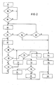
- the drop of the level on the main enable signal channel 29 to "Low” is queried via the enable input 28 of the control electronics module 15 in the query step 58. This query is made until the signal on the main enable signal channel 29 is actually "low", ie if the result N of the query step 58 is negative, this is repeated. With a positive result J of the interrogation step 58 takes place via the start input 39 in a query step 59, whether on the start line 37, a start level "High” is applied. If the result N of the query step 59 is negative, the query step 58 is again stirred.
- the control electronics module 15 controls the two power amplifiers 8, 9 and thus the two starter output stages 10, 11 and 10 in an activation step 60 This is done by the signal level on the activation output 14 is set to "high", at the same time the deactivation outputs 17, 19 have the signal level "low”.
- the run-up of the internal combustion engine is then performed by querying the speed sensor 52 by the control electronics module 15 via the control / data line 49, the speed-conditioning module 50 around the signal line 51. This is done in a query step 61.
- a query is made in a query step 62 via a time module integrated in the start control element 38 as to whether a certain maximum start time has already been reached.
- a further interrogation of the signal level on the enable input 28 takes place in a polling step 63, by checking whether the enable signal on the software release switching channel 26 still has the signal level "Low".
- a negative query result N of the query step 63 and a positive query result J of the query step 62 is stored in a memory step 64 in the data memory 56 of the control electronics module 15 that the internal combustion engine has an operating state in which no diagnosis of the hardware release switching channel 22 is possible .
- a deactivation step 65 the two power amplifiers 8, 9 are subsequently deactivated by "high" setting of the two deactivation outputs 17, 19 and the information that an unsuccessful end of the starting procedure has been reached is output in an output step 66 in the data memory 56.
- the negative query result N of the interrogation step 63 corresponds to the situation that a frictional connection is detected via the main enable signal channel 29 while the internal combustion engine is still starting.
- the activation of the magnetic switch 3 via the deactivation step 65 is interrupted regardless of the hardware release switching channel 22 in each case or not even begun.
- the entries in the data memory 56 from steps 64 and 66 are then transmitted from the control electronics module 15 to a corresponding output medium, e.g. an LCD screen (not shown) passed.
- the result of the interrogation step 68 is whether the signal on the magnetic switch diagnosis line 47 is "Low", positive J. If the result of the interrogation step 68 is negative N, the storage step 64 is continued, as explained above. In such a case, the fault to be stored is that the starter relay 4 still turns on, although the first deactivation output 17 is set to "High" for the associated first power amplifier 8.
- a further interrogation step 69 the query as to whether the signal on the enable input 28 has meanwhile changed to a "high" level. This is the case when frictional engagement between the engine and drive train is present, that is, in an internal combustion engine with automatic transmission, the selector lever of P / N is switched to a gear or when the clutch is released in an internal combustion engine with manual gearbox in gear.
- the auxiliary enable signal channels 31 and 34 via the auxiliary enable inputs 32 and 35 of the control electronics module 15th queried are for the sake of clarity in the flowchart of Fig. 2 not shown.
- the deactivation step 65 follows, as explained above.
- query step 70 is faulty because diagnostic line 44 is low, although second power amplifier 9 should have been disabled via hardware enable switch channel 22 and second control terminal 18.
- deactivation of the second occurs in a deactivation step 72 Power amplifier 9 by "high" setting of the second deactivation output 19 and "low” setting of the activation output 14th
- a subsequent query step 73 is again checked whether the signal at the second A / D converter 45 has changed from "low” to "high”, which would reflect a shutdown of the second power amplifier 9 via the control electronics module 15.
- a positive query result J of the interrogation step 73 there is clearly a fault in the hardware release switching channel 22, since the deactivation step 72 enabled the second power amplifier 9 to be switched off via the control electronics module 15, but not automatically from the hardware release switching channel 22 was switched off after completion of the release. Therefore, in this case, an output step 74 is made in the data memory 56 with the content that an error is present in the hardware enable switching channel 22. This error is displayed on the one hand on the LCD display and on the other hand visualized by driving the warning lamp 55 via the output line 54.
- the second power amplifier 9 can not be switched off either via the control electronics module 15 or via the hardware enable switching channel 22, or there is an error in the second A / D converter 45 in front.
- the cause of such errors may be an error in the output stage formed by the second power amplifier 9 and the second starter-stage output transistor 11, or a short to ground.
- an output step 75 a data entry into the data memory 56 of the content takes place so that the signal detected by the A / D converter 45 is permanently "low".
- the signal on the enable input 28 is checked by a query step 76, in which it is queried whether the received from the transmission control enable signal via the auxiliary enable input 32nd or in the case of a manual transmission over the release signal via the further auxiliary release input 35 by a "high" level indicates a frictional connection between the internal combustion engine and the drive train. If the result of the query is positive J, i. when indicated adhesion, the information is entered in an output step 77 in the data memory 56 that an error in the release input 28 measured release signal is present. This entry is then passed on to the LCD display. It then proceeds to the storage step 64, as explained above.
- the deactivation step 67 is continued and thus waited until, in the interrogation step 69, the signal at the enable input 28 has changed to a "high" level.
- the starting device 1 is dimensioned so that in case of a short circuit of the capacitor 78 to ground in the case of a "high" level on the main enable signal channel 29 still a "high” level is detected at the enable input 28.
- the software enable switch channel 26 is still active, even though the hardware enable switch channel 22 is no longer functional by the shorted capacitor 78.
- the starter 2 can thus still be controlled while the warning lamp 55 is turned on and a corresponding Warning message on the LCD display are issued, with which the user is requested to carry out a maintenance of the starting device 1.
- the internal combustion engine can be further started and operated via the software release switching channel 26 even in the event of an error in the hardware release switching channel 22.
- deactivation step 67 deactivating not first of the first power amplifier 8, as described above, but first of the second power amplifier 9.
- the deactivation of the first power amplifier 8 via the ending in the control terminal 16 branch of the hardware Release switching channel 22 are tested and diagnosed analogously to the above-described. In this way, in successive starts alternately at each start of the passage of the ending with the control terminals 16 and 18 respective branch of the hardware release switching channel 22 to the power amplifier 8 and 9, the starter output stage transistors 10 and 11 and the starter relay 4 or 5 tested.
- the controlled deactivation or non-deactivation of power amplifiers can take place in successive starting operations in a predetermined and / or statistical sequence, which is set up by a selector device, not shown.
- An interruption in the main enable signal channel 29 in the signal path after the diversion of the software release switching channel 26 before or after the branch node 21 or a short circuit of the capacitor 78, which affect the function of the hardware release switching channel 22, can by the described Diagnosis of the hardware release switching channel 23 can be reliably detected.
- Such an interruption can not usually be detected by the comparison of the enable signals on the inputs 28, 32 and 35 by the control electronics module 15 without the described method.
Landscapes
- Engineering & Computer Science (AREA)
- Chemical & Material Sciences (AREA)
- Combustion & Propulsion (AREA)
- Mechanical Engineering (AREA)
- General Engineering & Computer Science (AREA)
- Transportation (AREA)
- Combined Controls Of Internal Combustion Engines (AREA)
Claims (22)
- Dispositif de démarrage (1) pour un moteur à combustion interne,- comprenant un dispositif de commande de commutation (7) pour commander un démarreur (2), comprenant :- au moins un module de commutation de puissance (4, 5), qui relie le démarreur (2) à une source de tension (6) et qui est activé par le biais d'au moins une ligne de commande (16, 18) associée à l'au moins un module de commutation de puissance (4, 5) et au moins un étage de commande (10, 11) associé à l'au moins un module de commutation de puissance (4, 5) ;- une électronique de commande (15) pour commander l'au moins un module de commutation de puissance (4, 5) ;- un dispositif de libération (29 - 36) détectant le flux de forces du moteur à combustion interne, qui est réalisé de telle sorte que lorsqu'il n'y a pas de flux de forces entre le moteur à combustion interne et une transmission associée à celui-ci, il fournit, sur un canal de signal de libération (29, 31, 34) un signal de libération pour libérer l'opération de commutation d'activation par l'au moins une ligne de commande (16, 18), comprenant :- un premier canal de commutation de libération (22) fonctionnant indépendamment de l'électronique de commande (15),- un deuxième canal de commutation de libération (26) coopérant avec l'électronique de commande (15),- les canaux de commutation de libération (22, 26) étant prévus de manière à ce qu'une activation de l'opération de commutation d'activation n'ait lieu que dans une position de commutation de libération simultanée des canaux de commutation de libération (22, 26) ;
caractérisé par- un dispositif de diagnostic (40 - 45), au moins deux modules de commutation de puissance (4, 5) montés en série étant prévus et le dispositif de diagnostic (40 - 45) coopérant avec l'électronique de commande (15) et étant réalisé de telle sorte qu'à la fin de la fourniture du signal de libération (29) pour l'opération de commutation d'activation, il ne désactive pas au moins un module de commutation de puissance (4, 5) par le biais de l'électronique de commande (15) et que pour le diagnostic du premier canal de commutation de libération (22), il détecte l'état de commutation des étages de commande (10, 11) du module de commutation de puissance non désactive (4, 5) par le biais de lignes de diagnostic (41, 44) du dispositif de diagnostic (40 - 45), le dispositif de diagnostic (40 - 45) étant réalisé de telle sorte qu'il contrôle la coupure d'une sortie des étages de commande (10, 11) à la fin de la fourniture du signal de libération (29). - Dispositif de démarrage selon la revendication 1, caractérisé en ce que le premier canal de commutation de libération (22) est réalisé sous forme de canal de commutation de libération matériel.
- Dispositif de démarrage selon la revendication 1 ou 2, caractérisé en ce que le deuxième canal de commutation de libération (26) est réalisé sous forme de canal de commutation de libération logiciel et est commandé par le biais d'un micro-ordinateur de l'électronique de commande (15).
- Dispositif de démarrage selon l'une quelconque des revendications précédentes, caractérisé en ce que le dispositif de diagnostic (40 - 45) comprend au moins un convertisseur A/N pour détecter la position de commutation de libération.
- Dispositif de démarrage selon la revendication 1, caractérisé en ce que le dispositif de diagnostic (40 - 45) est réalisé de telle sorte que, par comparaison avec l'opération de démarrage précédente, il ne désactive pas à chaque fois au moins un autre module de commutation de puissance (4, 5) dans le cas de commandes successives du démarreur pour le moteur à combustion interne, à la fin de la fourniture du signal de libération pour l'opération de commutation d'activation.
- Dispositif de démarrage selon la revendication 5, caractérisé en ce que le dispositif de diagnostic (40 - 45) présente un dispositif de sélection par le biais duquel a lieu une non-désactivation commandée de modules de commutation de puissance en cas de commandes successives du démarreur en fonction d'une séquence de non-désactivation prédéfinie.
- Dispositif de démarrage selon l'une quelconque des revendications précédentes, caractérisé en ce que le dispositif de diagnostic (40 - 45) est réalisé de telle sorte qu'à la détection d'un état de commutation actif sur l'une des lignes de commande (16, 18) à la fin de la fourniture du signal de libération, il introduise par le biais de l'électronique de commande (15) une désactivation de tous les modules de commutation de puissance (4, 5).
- Dispositif de démarrage selon l'une quelconque des revendications précédentes, caractérisé en ce que le dispositif de diagnostic (40 - 45) est réalisé de telle sorte qu'à la détection d'un état de commutation actif sur l'une des lignes de commande (16, 18) à la fin de la fourniture du signal de libération, il commande par le biais de l'électronique de commande (15) un générateur de signal d'avertissement (55).
- Dispositif de démarrage selon l'une quelconque des revendications précédentes, caractérisé en ce que le dispositif de diagnostic (40 - 45) est réalisé de telle sorte qu'à la détection d'un état de commutation actif sur l'une des lignes de commande (16, 18) à la fin de la fourniture du signal de libération, il autorise par le biais de l'électronique de commande (15) une entrée d'une séquence de données associée à l'erreur dans un support de mémoire (56) lisible coopérant avec l'électronique de commande (15).
- Dispositif de démarrage selon l'une quelconque des revendications précédentes, caractérisé par un capteur de régime (52) coopérant avec le dispositif de libération (29 - 36) pour détecter le fonctionnement du moteur à combustion interne.
- Dispositif de démarrage selon l'une quelconque des revendications précédentes, caractérisé en ce que le dispositif de démarrage (29 - 36) présente : le canal de signal de libération (29), qui est réalisé de telle sorte qu'il fournisse, en fonction d'un premier paramètre de fonctionnement du moteur à combustion interne, un signal de libération pour la libération de l'opération de commutation d'activation et un autre canal de signal de libération (31, 34), qui est réalisé de telle sorte qu'il fournisse, en fonction d'un deuxième paramètre de fonctionnement du moteur à combustion interne, un deuxième signal de libération indépendant qui est détecté par l'électronique de commande (15).
- Dispositif de démarrage selon la revendication 11, caractérisé en ce que le dispositif de libération (29 - 36) pour la détection de l'un des deux paramètres de fonctionnement, présente au moins un capteur de flux de forces (30, 33, 36) détectant le flux de forces entre un moteur et une transmission ou une chaîne cinématique du moteur à combustion interne.
- Procédé pour démarrer un moteur à combustion interne avec un démarreur (2),- dans lequel un dispositif de commande de commutation (7) commande le démarreur (2), en ce que- au moins un module de commutation de puissance (4, 5) relie le démarreur (2) à une source de tension (6) et le module de commutation de puissance (4, 5) est activé par le biais d'au moins une ligne de commande (16, 18) associée à l'au moins un module de commutation de puissance (4, 5) et d'au moins un étage de commande (10, 11) associé à l'au moins un module de commutation de puissance (4, 5) ;- une électronique de commande (15) commande l'au moins un module de commutation de puissance (4, 5) ;
où- un dispositif de libération (29 - 36) du dispositif de commande de commutation (7) détectant le flux de forces du moteur à combustion interne lorsqu'il n'y a aucun flux de forces entre le moteur à combustion interne et une transmission associée à celui-ci, fournit un signal de libération pour libérer l'opération de commutation d'activation par le biais de l'au moins une ligne de commande (16, 18),
où- un premier canal de commutation de libération (22) du dispositif de libération (29 - 26) indépendant de l'électronique de commande (15) commute en fonction du signal de libération et- un deuxième canal de commutation de libération (26) du dispositif de libération (29 - 36) coopérant avec l'électronique de commande (15) commute en fonction du signal de libération et- les canaux de commutation de libération (22, 26) introduisent l'opération de commutation d'activation uniquement pour une position de commutation de libération simultanée du premier et du deuxième canal de libération (22, 26) ;
caractérisé par- un dispositif de diagnostic (40 - 45) du dispositif de commande de commutation (7), au moins deux modules de puissance (4, 5) montés en série étant prévus et le dispositif de diagnostic (40 - 45) coopérant avec l'électronique de commande (15) et, à la fin de la fourniture du signal de libération (29) pour l'opération de commutation d'activation, ne désactivant pas par le biais de l'électronique de commande (15) au moins un module de commutation de puissance (4, 5), et pour le diagnostic du premier canal de commutation de libération (22), détectant l'état de commutation des étages de commande (10, 11) du module de commutation de puissance (4, 5) non désactivé, par le biais de lignes de diagnostic (41, 44) du dispositif de diagnostic (40 - 45), le dispositif de diagnostic (40 - 45) étant réalisé de telle sorte qu'il surveille la commutation d'une sortie des étages de commande (10, 11) à la fin de la fourniture du signal de libération (29). - Procédé selon la revendication 13, caractérisé en ce que le dispositif de diagnostic (40 - 45) détecte la position de commutation de libération par le biais d'au moins un convertisseur A/N (42, 45).
- Procédé selon la revendication 13 ou 14, caractérisé en ce que le dispositif de diagnostic (40 - 45), en cas de commandes successives du démarreur pour le moteur à combustion interne, à la fin de la fourniture du signal de libération pour l'opération de commutation d'activation, par comparaison avec le programme de démarrage précédent, ne désactive pas à chaque fois au moins un autre module de commutation de puissance (4, 5).
- Procédé selon la revendication 15, caractérisé en ce qu'un dispositif de sélection du dispositif de diagnostic (40 - 45) effectue une non-désactivation commandée de modules de commutation de puissance (4, 5) en cas de commandes successives du démarreur en fonction d'une séquence de non-désactivation prédéfinie.
- Procédé selon l'une quelconque des revendications 13 à 16, caractérisé en ce que le dispositif de diagnostic (40 - 45), dans le cas d'une détection d'un état de commutation actif à la fin de la fourniture du signal de libération, introduit par le biais de l'électronique de commande une désactivation de tous les modules de commutation de puissance (4, 5).
- Procédé selon l'une quelconque des revendications 13 à 17, caractérisé en ce que le dispositif de diagnostic (40 - 45), dans le cas d'une détection d'un état de commutation actif à la fin de la fourniture du signal de libération, commande par le biais de l'électronique de commande (15) un générateur de signal d'avertissement (55).
- Procédé selon l'une quelconque des revendications 13 à 17, caractérisé en ce que le dispositif de diagnostic (40 - 45), dans le cas d'une détection d'un état de commutation actif à la fin de la fourniture du signal de libération, mémorise par le biais de l'électronique de commande (15) une séquence de données associée à l'erreur dans un support de mémoire (56) lisible coopérant avec l'électronique de commande (15).
- Procédé selon l'une quelconque des revendications 13 à 19, caractérisé en ce que le dispositif de libération (29 - 36) pour la détection de la marche du moteur à combustion interne coopère avec un capteur de régime (52).
- Procédé selon l'une quelconque des revendications 13 à 20, caractérisé en ce que le dispositif de libération (29 - 36) comprend le canal de signal de libération (29), qui fournit, en fonction d'un premier paramètre de fonctionnement du moteur à combustion interne, un signal de libération pour la libération de l'opération de commutation d'activation, et un autre canal de signal de libération (31, 34), qui fournit, en fonction d'un deuxième paramètre de fonctionnement du moteur à combustion interne, un deuxième signal de libération indépendant, qui est détecté par l'électronique de commande (15).
- Procédé selon la revendication 21, caractérisé en ce que le dispositif de libération (29 - 36) détecte le flux de forces entre un moteur et une transmission ou une chaîne cinématique du moteur à combustion interne en tant que l'un des deux paramètres de fonctionnement.
Applications Claiming Priority (5)
| Application Number | Priority Date | Filing Date | Title |
|---|---|---|---|
| DE10212510 | 2002-03-21 | ||
| DE10212510 | 2002-03-21 | ||
| DE10239150 | 2002-08-27 | ||
| DE10239150A DE10239150A1 (de) | 2002-03-21 | 2002-08-27 | Startvorrichtung für eine Brennkraftmaschine |
| PCT/DE2003/000524 WO2003081026A1 (fr) | 2002-03-21 | 2003-02-20 | Dispositif de demarrage pour moteur a combustion interne et procede de demarrage d'un moteur a combustion interne |
Publications (2)
| Publication Number | Publication Date |
|---|---|
| EP1490596A1 EP1490596A1 (fr) | 2004-12-29 |
| EP1490596B1 true EP1490596B1 (fr) | 2013-01-16 |
Family
ID=28455522
Family Applications (1)
| Application Number | Title | Priority Date | Filing Date |
|---|---|---|---|
| EP03714645A Expired - Lifetime EP1490596B1 (fr) | 2002-03-21 | 2003-02-20 | Dispositif de demarrage pour moteur a combustion interne et procede de demarrage d'un moteur a combustion interne |
Country Status (3)
| Country | Link |
|---|---|
| US (1) | US7156063B2 (fr) |
| EP (1) | EP1490596B1 (fr) |
| WO (1) | WO2003081026A1 (fr) |
Families Citing this family (13)
| Publication number | Priority date | Publication date | Assignee | Title |
|---|---|---|---|---|
| US8069831B2 (en) * | 2004-11-26 | 2011-12-06 | Fujitsu Ten Limited | Method and apparatus for start control of a vehicle |
| EP1891325B1 (fr) * | 2005-05-26 | 2019-08-21 | Volvo Lastvagnar AB | Procede de commande de l'alimentation d'un demarreur electrique |
| DE102005034602B4 (de) * | 2005-07-25 | 2015-07-16 | Robert Bosch Gmbh | Verfahren zum Betreiben eines Kraftfahrzeugs mit einer Brennkraftmaschine, Computerprogramm-Produkt, elektrisches Speichermedium für eine Steuer- und/oder Regeleinrichtung sowie Steuer- und/oder Regeleinrichtung für ein Kraftfahrzeug |
| JP4121095B2 (ja) * | 2006-04-19 | 2008-07-16 | 富士通テン株式会社 | 電源管理装置、制御システム、及び制御方法 |
| US7956477B2 (en) * | 2007-10-15 | 2011-06-07 | Ford Global Technologies, Llc | Starter relay control |
| DE102009028292A1 (de) * | 2009-08-06 | 2011-02-10 | Robert Bosch Gmbh | Vorrichtung zum Starten einer Verbrennungskraftmaschine eines Kraftfahrzeugs mit verbesserter Steuereinheit |
| DE102009029288A1 (de) * | 2009-09-09 | 2011-03-10 | Robert Bosch Gmbh | Vorrichtung zum Starten einer Verbrennungskraftmaschine mit einer reduzierten Anzahl von Steuerleitungen |
| US9157405B2 (en) | 2012-10-29 | 2015-10-13 | Mtu America Inc. | Starter motor testing device |
| KR101619227B1 (ko) * | 2014-10-20 | 2016-05-10 | 현대자동차주식회사 | 차량용 미들 도어 또는 스텝의 고장 진단 방법 |
| JP6390555B2 (ja) * | 2015-08-28 | 2018-09-19 | 株式会社デンソー | 電子制御装置及びコンピュータプログラム |
| US11002238B2 (en) * | 2019-02-13 | 2021-05-11 | Pratt & Whitney Canada Corp. | Method and system for starting an engine |
| US11646566B2 (en) | 2020-12-16 | 2023-05-09 | Lear Corporation | Apparatus for permanent supply with a switch |
| US12088183B2 (en) | 2021-10-19 | 2024-09-10 | Lear Corporation | Electrical system |
Family Cites Families (9)
| Publication number | Priority date | Publication date | Assignee | Title |
|---|---|---|---|---|
| US3675033A (en) * | 1969-03-31 | 1972-07-04 | Peugeot | Device for starting and stopping a diesel engine |
| US4031403A (en) * | 1973-08-03 | 1977-06-21 | The Lucas Electrical Company Limited | Road vehicle electrical systems |
| DE3834855A1 (de) * | 1988-10-13 | 1990-04-19 | Bayerische Motoren Werke Ag | Starter eines kraftfahrzeugs mit integrierter leistungselektronik |
| JPH05240132A (ja) * | 1992-02-28 | 1993-09-17 | Aisin Seiki Co Ltd | オートマチック車のスターター装置 |
| DE19532484B4 (de) | 1995-02-03 | 2005-08-25 | Robert Bosch Gmbh | Startvorrichtung zum Starten einer Brennkraftmaschine |
| JPH0953551A (ja) * | 1995-08-11 | 1997-02-25 | Jatco Corp | スタータの制御装置 |
| DE19811176A1 (de) | 1997-10-11 | 1999-04-15 | Bosch Gmbh Robert | Anordnung und Verfahren zur Steuerung einer elektrischen Maschine |
| US6104157A (en) * | 1997-10-11 | 2000-08-15 | Robert Bosch Gmbh | Apparatus and method for controlling an electrical starter of an internal combustion engine |
| DE19844454C2 (de) * | 1998-09-28 | 2001-11-29 | Siemens Ag | Steuerschaltung zwischen einem Port eines Mikroprozessors und einem elektrischen Verbraucher und Verfahren zum Aufrechterhalten des momentanen Zustands eines elektrischen Verbrauchers während eines Einbruchs der Versorgungsspannung |
-
2003
- 2003-02-20 US US10/507,462 patent/US7156063B2/en not_active Expired - Fee Related
- 2003-02-20 EP EP03714645A patent/EP1490596B1/fr not_active Expired - Lifetime
- 2003-02-20 WO PCT/DE2003/000524 patent/WO2003081026A1/fr not_active Ceased
Also Published As
| Publication number | Publication date |
|---|---|
| WO2003081026A1 (fr) | 2003-10-02 |
| US7156063B2 (en) | 2007-01-02 |
| EP1490596A1 (fr) | 2004-12-29 |
| US20050139181A1 (en) | 2005-06-30 |
Similar Documents
| Publication | Publication Date | Title |
|---|---|---|
| EP2265481B1 (fr) | Procédé et dispositif de commande d'un moteur électrique d'un entraînement hybride pour une disponibilité améliorée | |
| DE102009047233B4 (de) | Ein Verfahren und Vorrichtung zum Steuern des automatischen Startens und Abschalten des Verbrennungsmotors eines Fahrzeugs | |
| EP2077401B1 (fr) | Agencement d'actionneur pour une transmission de véhicule automobile et procédé de fonctionnement d'un agencement d'actionneur | |
| EP1521917B1 (fr) | Procede et dispositif permettant d'ameliorer la securite de fonctionnement lors de l'actionnement d'un embrayage et/ou d'une boite de vitesses | |
| EP1490596A1 (fr) | Dispositif de demarrage pour moteur a combustion interne et procede de demarrage d'un moteur a combustion interne | |
| DE102008042887A1 (de) | Verfahren zur Verfügbarkeitserhöhung bei Hybridfahrzeugen | |
| DE102007009831B4 (de) | Anzeige-Auslöseeinheit in einem Kraftfahrzeug mit einer automatischen Start Stopp Funktion | |
| EP2739883B1 (fr) | Procédé et appareil de commande d'un élément d'une chaîne cinématique | |
| DE102009054765A1 (de) | Elektronische Steuereinheit für einen Motor | |
| DE112011100582B4 (de) | Smart Aktor,Verfahren und Steuerungssystem zur Betätigung einer Kupplung | |
| DE102011110152A1 (de) | Verfahren zum Steuern eines Fahrzeugs während eines Hilfspumpenausfalls | |
| DE102011081093A1 (de) | Startsystem, Verfahren und Computerprogrammprodukt zum Starten einer Brennkraftmaschine | |
| DE60035646T2 (de) | Elektronische Steuerung einer Drosselklappe | |
| EP1679729B1 (fr) | Dispositif destiné à une émission de signal sûre | |
| EP2360077B1 (fr) | Véhicule automobile avec fonction arrêt-démarrage | |
| DE10239150A1 (de) | Startvorrichtung für eine Brennkraftmaschine | |
| EP1397729B1 (fr) | Dispositif de production securisee de signal | |
| WO2011015455A1 (fr) | Procédé et dispositif pour contrôler un appareil pour la commutation d'un starter | |
| DE19939051A1 (de) | Vorrichtung und Verfahren zur Erzeugung eines Kraftstoffhochdrucks | |
| DE10103638B4 (de) | Vorrichtung und Verfahren zum Anlassen einer Brennkraftmaschine | |
| EP1446576B1 (fr) | Dispositif de demarrage pour moteur a combustion interne | |
| DE102005034602B4 (de) | Verfahren zum Betreiben eines Kraftfahrzeugs mit einer Brennkraftmaschine, Computerprogramm-Produkt, elektrisches Speichermedium für eine Steuer- und/oder Regeleinrichtung sowie Steuer- und/oder Regeleinrichtung für ein Kraftfahrzeug | |
| DE10040246B4 (de) | Verfahren und Vorrichtung zur Ansteuerung wenigstens eines Verbrauchers | |
| DE102010029210B4 (de) | Verfahren und Vorrichtung zum Starten und Stoppen einer Brennkraftmaschine | |
| DE10139855B4 (de) | Kraftfahrzeug mit einem elektronischen Getriebesteuergerät für ein Automatikgetriebe |
Legal Events
| Date | Code | Title | Description |
|---|---|---|---|
| PUAI | Public reference made under article 153(3) epc to a published international application that has entered the european phase |
Free format text: ORIGINAL CODE: 0009012 |
|
| 17P | Request for examination filed |
Effective date: 20041021 |
|
| AK | Designated contracting states |
Kind code of ref document: A1 Designated state(s): AT BE BG CH CY CZ DE DK EE ES FI FR GB GR HU IE IT LI LU MC NL PT SE SI SK TR |
|
| 17Q | First examination report despatched |
Effective date: 20090330 |
|
| R17C | First examination report despatched (corrected) |
Effective date: 20091002 |
|
| GRAP | Despatch of communication of intention to grant a patent |
Free format text: ORIGINAL CODE: EPIDOSNIGR1 |
|
| GRAS | Grant fee paid |
Free format text: ORIGINAL CODE: EPIDOSNIGR3 |
|
| GRAA | (expected) grant |
Free format text: ORIGINAL CODE: 0009210 |
|
| AK | Designated contracting states |
Kind code of ref document: B1 Designated state(s): DE FR IT |
|
| REG | Reference to a national code |
Ref country code: DE Ref legal event code: R096 Ref document number: 50314667 Country of ref document: DE Effective date: 20130314 |
|
| PLBE | No opposition filed within time limit |
Free format text: ORIGINAL CODE: 0009261 |
|
| STAA | Information on the status of an ep patent application or granted ep patent |
Free format text: STATUS: NO OPPOSITION FILED WITHIN TIME LIMIT |
|
| 26N | No opposition filed |
Effective date: 20131017 |
|
| REG | Reference to a national code |
Ref country code: DE Ref legal event code: R097 Ref document number: 50314667 Country of ref document: DE Effective date: 20131017 |
|
| PGFP | Annual fee paid to national office [announced via postgrant information from national office to epo] |
Ref country code: IT Payment date: 20140228 Year of fee payment: 12 Ref country code: FR Payment date: 20140218 Year of fee payment: 12 |
|
| REG | Reference to a national code |
Ref country code: FR Ref legal event code: ST Effective date: 20151030 |
|
| PG25 | Lapsed in a contracting state [announced via postgrant information from national office to epo] |
Ref country code: IT Free format text: LAPSE BECAUSE OF NON-PAYMENT OF DUE FEES Effective date: 20150220 |
|
| PG25 | Lapsed in a contracting state [announced via postgrant information from national office to epo] |
Ref country code: FR Free format text: LAPSE BECAUSE OF NON-PAYMENT OF DUE FEES Effective date: 20150302 |
|
| PGFP | Annual fee paid to national office [announced via postgrant information from national office to epo] |
Ref country code: DE Payment date: 20160426 Year of fee payment: 14 |
|
| REG | Reference to a national code |
Ref country code: DE Ref legal event code: R119 Ref document number: 50314667 Country of ref document: DE |
|
| PG25 | Lapsed in a contracting state [announced via postgrant information from national office to epo] |
Ref country code: DE Free format text: LAPSE BECAUSE OF NON-PAYMENT OF DUE FEES Effective date: 20170901 |