EP1491288B1 - Méthode de chanfreinage d'une pièce en forme de plaque - Google Patents
Méthode de chanfreinage d'une pièce en forme de plaque Download PDFInfo
- Publication number
- EP1491288B1 EP1491288B1 EP04014903A EP04014903A EP1491288B1 EP 1491288 B1 EP1491288 B1 EP 1491288B1 EP 04014903 A EP04014903 A EP 04014903A EP 04014903 A EP04014903 A EP 04014903A EP 1491288 B1 EP1491288 B1 EP 1491288B1
- Authority
- EP
- European Patent Office
- Prior art keywords
- robot
- chamfering
- robot hand
- axis
- plate
- Prior art date
- Legal status (The legal status is an assumption and is not a legal conclusion. Google has not performed a legal analysis and makes no representation as to the accuracy of the status listed.)
- Expired - Lifetime
Links
Images








Classifications
-
- B—PERFORMING OPERATIONS; TRANSPORTING
- B24—GRINDING; POLISHING
- B24B—MACHINES, DEVICES, OR PROCESSES FOR GRINDING OR POLISHING; DRESSING OR CONDITIONING OF ABRADING SURFACES; FEEDING OF GRINDING, POLISHING, OR LAPPING AGENTS
- B24B9/00—Machines or devices designed for grinding edges or bevels on work or for removing burrs; Accessories therefor
- B24B9/02—Machines or devices designed for grinding edges or bevels on work or for removing burrs; Accessories therefor characterised by a special design with respect to properties of materials specific to articles to be ground
- B24B9/06—Machines or devices designed for grinding edges or bevels on work or for removing burrs; Accessories therefor characterised by a special design with respect to properties of materials specific to articles to be ground of non-metallic inorganic material, e.g. stone, ceramics, porcelain
- B24B9/08—Machines or devices designed for grinding edges or bevels on work or for removing burrs; Accessories therefor characterised by a special design with respect to properties of materials specific to articles to be ground of non-metallic inorganic material, e.g. stone, ceramics, porcelain of glass
- B24B9/10—Machines or devices designed for grinding edges or bevels on work or for removing burrs; Accessories therefor characterised by a special design with respect to properties of materials specific to articles to be ground of non-metallic inorganic material, e.g. stone, ceramics, porcelain of glass of plate glass
- B24B9/107—Machines or devices designed for grinding edges or bevels on work or for removing burrs; Accessories therefor characterised by a special design with respect to properties of materials specific to articles to be ground of non-metallic inorganic material, e.g. stone, ceramics, porcelain of glass of plate glass for glass plates while they are turning
-
- B—PERFORMING OPERATIONS; TRANSPORTING
- B24—GRINDING; POLISHING
- B24B—MACHINES, DEVICES, OR PROCESSES FOR GRINDING OR POLISHING; DRESSING OR CONDITIONING OF ABRADING SURFACES; FEEDING OF GRINDING, POLISHING, OR LAPPING AGENTS
- B24B49/00—Measuring or gauging equipment for controlling the feed movement of the grinding tool or work; Arrangements of indicating or measuring equipment, e.g. for indicating the start of the grinding operation
-
- B—PERFORMING OPERATIONS; TRANSPORTING
- B25—HAND TOOLS; PORTABLE POWER-DRIVEN TOOLS; MANIPULATORS
- B25J—MANIPULATORS; CHAMBERS PROVIDED WITH MANIPULATION DEVICES
- B25J9/00—Program-controlled manipulators
- B25J9/16—Program controls
- B25J9/1656—Program controls characterised by programming, planning systems for manipulators
- B25J9/1664—Program controls characterised by programming, planning systems for manipulators characterised by motion, path, trajectory planning
Definitions
- the present invention relates to a method for chamfering a plate-like member, in particular a method for chamfering an edge portion of a glass sheet.
- a chamfering machine for a glass sheet is one which uses a robot hand to hold a glass sheet to be chamfered and chamfers the entire edge portion of the glass sheet by moving and rotating the robot hand while pressing an edge portion of the glass sheet against a grinding wheel (for example, JP-A-10-296600 ).
- a glass sheet has a linear edge portion or a corner portion brought in contact with the uppermost position of the grinding wheel to be chamfered.
- the contacting point is moved only when chamfering a recessed portion of a glass sheet.
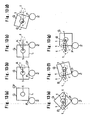
- Chamfering a linear edge portion or a corner portion of a glass sheet is performed by pressing an edge portion of the glass sheet against one point P of a grinding wheel 2 held by a robot hand 1 as shown in Figs. 13 (a) to (g) .
- the moving trajectory depicted by a robot hand 1 is a straight line parallel with the linear portion L as shown by arrows A in Figs. 13 (a) to (c) .
- the moving trajectory is a large circular arc as shown by arrows B in Figs. 13 (d) to (g) . This is because the robot hand is moved to rotate the glass sheet G so as to perform chamfering at the uppermost position of the grinding wheel. By repeating this movement for four sides of the glass sheet G, the entire edge portion of the glass sheet as a single sheet is chamfered by the grinding wheel 2.
- the moving trajectory of the robot hands has a circular arc shape when chamfering a corner portion of a glass sheet G
- the chamfered corner portion has an angular shape as shown in Fig. 11 since the moving trajectory actually comprises polygonal lines, which are formed by dividing a circular arc at plural points and connecting the respective points.
- the conventional chamfering machines for a glass sheet G have caused a disadvantage that it is difficult to perform chamfering with good precision.
- the moving trajectory becomes rougher since the number of the dividing points of the circular arc as the moving trajectory of the robot hands for chamfering a corner portion decreases. From the viewpoint of maintaining required chamfering precision, there is a limitation to an increase in the moving speed of the robot hands.
- JP 2002 120134 A discloses a chamfering device of a plate body capable of properly preventing chamfering burning.
- a glass plate positioned at a plate arranging position by a plate arranging device is held by a robot and it is transferred upward above a grinding wheel of a grinding wheel device. Thereafter, an edge part of the glass plate is brought into contact with the grinding wheel, and an overall periphery of the edge part is chamfered and worked by moving the glass plate.
- FR-A-2 545 025 discloses a machine for edging or polishing flat panes such as windows or mirrors comprising a turntable equipped with suckers for gripping the sheet of glass.
- a grinder and its drive motor are mounted on a carriage guided in straight translational movement in a direction parallel to the plane of the glass supported by the turntable, wherein the plane of the glass supported by its turntable is inclined by approximately 45° to the horizontal.
- JP 2001 261357 discloses a method for fabrication of sheet glass and a corresponding apparatus according to which the sheet glass is prevented from being scratched.
- a glass cutting and breaking machine and a chamfering machine are arranged so that they are opposed to each other on both sides of a glass plate sucking and conveying machine.
- the present invention is proposed in consideration of the circumstances stated earlier. It is an object of the present invention to provide a method for chamfering a plate-like member, which is capable of increasing productivity and chamfering precision.
- the present invention provides a method for chamfering a plate-like member, which comprises chamfering a peripheral edge portion of a plate-like member with a robot hand being moved and rotated while using the robot hand to hold the plate-like member and press the peripheral edge against a rotating grinding wheel of a chamfering machine, and which further comprises chamfering the peripheral edge with the robot hand being moved and rotated so that a grinding point, at which an edge of the plate-like member and a peripheral surface of the grinding wheel contact, moves along the peripheral surface of the grinding wheel, wherein the plate-like member has the peripheral edge so that the center of rotation of the robot hand moves along a straight line connecting between the center of rotation of the robot hand and the center of the grinding wheel.
- a method for chamfering a plate-like member which comprises chamfering a peripheral edge portion of a plate-like member with a robot hand being moved and rotated while using the robot hand to hold the plate-like member and press the peripheral edge against a rotating grinding wheel of a cham
- the plate-like member has the peripheral edge chambered with the robot hand being moved and rotated so that the grinding point between an edge of the plate-like member and a peripheral surface of the grinding wheel contact moves along the peripheral surface of the grinding wheel.
- the robot hand is rotatably provided on a sixth axis of a six-axis articulated robot, and the edge portion of the plate-like member is chamfered while the robot is in such a posture that an arm linked to the fifth axis of the articulated robot is horizontal and perpendicular to a plane parallel with axes of arms respectively linked to the second axis, the third axis and the fourth axis.
- the edge portion of the plate-like member is chamfered while the robot is in such a posture that an arm linked to the fifth axis of the articulated robot is horizontal and perpendicular to a plane parallel with axes of arms respectively linked to the second axis, the third axis and the fourth axis.
- the robot for chamfering is also served as a robot for scribing and breaking off the plate-like member. Accordingly, it is possible to eliminate positioning for chamfering and to effectively perform the processes from the cutting process to the chamfering process. It is also possible to reduce the facility space.
- the plate-like member has the peripheral edge chambered with the robot hand being moved and rotated so that the grinding point between an edge of the plate-like member and a peripheral surface of the grinding wheel contact moves along the peripheral surface of the grinding wheel.
- the plate-like member has the peripheral edge so that the center of rotation of the robot hand moves along a straight line connecting between the center of rotation of the robot hand and the center of the grinding wheel, it is possible to make the moving distance of the robot hand to the minimum. Accordingly, it is possible not only to chamfer the plate-like member so as to have the corner or corners formed in a circular arc-shape.
- the robot for chamfering is also served as a robot for scribing and breaking off the plate-like member, it is possible to eliminate positioning for chamfering and to effectively perform the processes from the cutting process to the chamfering process. It is also possible to reduce the facility space.
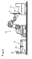
- Fig. 1 to Fig. 4 show machining equipment for a glass sheet, wherein a single robot 14 is provided between a chamfering machine 10 and a cutting machine 12, and wherein a series of machining processes from scribing and breaking off of a glass sheet G to chamfering of the glass sheet are performed by use of the single robot 14.
- the moving trajectories of the robot 14 are controlled so that a robot hand 16 of the robot moves along a moving trajectory required for scribing and breaking off and a moving trajectory required for chamfering.
- the motion of the robot hand 16 is controlled so as to hold a central position of the scribed and broken off glass sheet G during chamfering by the robot controller.
- FIG. 1 is a front view showing a status wherein the glass sheet is scored by the robot in the machine equipment.
- Fig. 2 is a top plan view of the status shown in Fig. 1 .
- Fig. 3 is a front view showing a status wherein the glass sheet is chamfered in the machine equipment.
- Fig. 4 is a top plan view of the status shown in Fig. 3 .
- Fig. 5 is a front view of the robot shown in Fig. 1 .
- the cutting machine 12 is configured so as to have a chuck for opening 24 provided on a table 22 with a suction pad 20.
- a rectangular glass sheet (original sheet) 1G before scribing and breaking off is conveyed to the table 22 by, e.g., an unshown conveyer.
- the glass sheet 1G is sucked and held by the suction pad 20 of the table shown in Fig. 1 to be positioned at a certain position on the table 22.
- the robot hand 16 has a cutter 26 provided thereon to score the glass sheet 1G.
- the cutter 26 is provided on the robot hand 16 through an unshown inverting mechanism.
- the cutter When scoring the glass sheet 1G, the cutter is directed so as to confront the glass sheet 1G as shown in Fig. 1 .
- the cutter is inverted and withdrawn from a projected position to be housed.
- the glass sheet 1G which has been scored by the cutter 26, is held by the robot hand 16, and a peripheral portion of the glass sheet to be scribed and broken off is inserted into the chuck for scribing and breaking off 24. Then, the robot hand 16 is moved in a direction to snap the peripheral portion.
- the glass sheet G is formed so as to have a final product shape by having the peripheral portions snapped along the scores.
- the glass sheet G is conveyed to the chamfering machine 10 by movement of the robot 14, being held on the robot hand 16, as shown in Fig. 3 and Fig. 4 .
- the robot 14 is a six-axis articulated robot as shown in Fig. 5 and is rotatable about the respective axes S1, S2, S3, S4, S5 and S6.
- the robot hand 16 is provided with a suction pad, by which the glass sheet G is sucked and held and is conveyed to the chamfering machine 10.
- the chamfering machine 10 has a rotating grinding wheel 30 (corresponding to the grinding wheel in Claims) as shown in Fig. 3 and Fig. 4 .
- the glass sheet G, which is sucked and held by the robot hand 16 has a peripheral portion pressed against an upper portion of the rotating grinding wheel 30, being at a standing position, as shown in Figs. 6(a) to (g) .
- the motion of the robot hand 16 is controlled so that the entire peripheral portion of the glass sheet G is brought into contact with the grinding wheel 30.
- the glass sheet G has the entire peripheral portion chamfered.
- the chamfering machine 10 is applicable to a glass sheet to have a part of the peripheral portion chamfered.
- the glass sheet G that has been chamfered is conveyed to a conveyer (not shown), such as a belt conveyer, by the robot 14 and is released from the robot hand 16 of the robot 14 there.
- a conveyer such as a belt conveyer
- Figs. 6(a) to (g) correspond to the motion for chamfering a linear portion L of the glass sheet G.
- the chamfering steps shown in Figs. 6(c) to (g) correspond to the motion for chamfering a corner portion CP of the glass sheet G.
- the robot hand 16 rotates the glass sheet G in the clockwise direction in Figs. 6(a) to (g)
- the robot hand follows a trajectory A to vertically move along a straight line Q connecting between the center of rotation 0 1 of the robot hand 16 and the center of rotation 0 2 of the grinding wheel 30 to chamfer the entire peripheral portion of the glass sheet G.
- the motion of a conventional robot hand 1 shown in Figs. 13(a) to (g) comprises a linear trajectory A and a circular arc trajectory B since the glass sheet G is chamfered, being pressed against a single point P of a grinding wheel 2.
- the moving amounts of the robot hands 1 and 16 are compared with each other in the case of using the machine according to the present invention shown in Figs. 1 to 4 and the conventional machine shown in Figs. 13(a) to (g) .
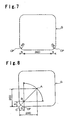
- the glass sheets G to be used for comparison were square glass sheets having a side length of 400 mm and a radius of curvature R of 5 mm at each of the corner portions CP.
- the circular arc trajectory B followed by the conventional robot hand 1 was actually a combination of straight lines, the trajectory B was regarded as being a circular arc since there was no substantially different between a combination of straight lines and a circular arc in terms of calculating the moving amount.
- a comparison of both moving amounts reveals that the machine according to the present invention can significantly reduce the moving amount since the moving amount in the conventional machine having a fixed grinding point is 3292.7 mm while the moving amount in the machine having a movable grinding point according to the present invention is 646.6 mm.
- a comparison of both moving amounts at the corner portions CP reveals that the moving amount in the machine according to the present invention is reduced to about 1/10 since the moving amount in the conventional machine is 1732.7 mm while the machine according to the present invention is 183.2 mm.
- the glass sheet 1G is chamfered so as to have an angular form at a corner portion CP as shown in Fig. 11 since the circular arc forming the moving trajectory comprises a combination of linear trajectories connecting points. Accordingly, the conventional chamfering machines has a disadvantage that chamfering precision is reduced when an attempt is made to increase the moving speed of the robot hand for an increase in productivity.
- the chamfering equipment of the present invention it is possible to minimize the moving distance of the robot hand 16 since the moving trajectory of the center of rotation 0 1 of the robot hand 16 at each of the corners depicts a straight line, not a circular arc. It is also possible to prevent the moving trajectory of the robot hand from being rough even if the moving speed of the robot hand increases. Accordingly, in accordance with the chamfering equipment of the present invention, it is possible to increase chamfering precision since it is possible to chamfer the corners CP in a smooth circular arc-shape as shown in Fig. 12 even if the moving speed of the robot hand increases.
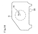
- Fig. 14 is a schematic view explaining the optimum position sucked and held by the robot hand when chamfering a peripheral edge portion of an automobile side windshield G having a unique shape.
- the center of gravity O 3 of the side windshield G is the optimum position to sucked and held by the robot hand 16. While the side windshield G is held by the robot hand with the center of rotation (holding center) O 1 of the robot hand aligned with the center of the gravity O 3 , the side windshield G has the entire peripheral edge portion chamfered by the grinding wheel 30 in accordance with the chamfering process shown in Figs. 6(a) to (g) . Thus, it is possible to minimize the deviation in the distance between the center of rotation of the robot hand 16 and the contour of the side windshield G. Accordingly, chamfering quality is stabilized since it is possible to decrease a change in the rotational speed of the side windshield G or the moving speed of the robot arm when the chamfering speed at the entire peripheral edge portion of the side windshield G is controlled to be uniform.
- the chamfering precision is significantly affected by the backlash of the respective axes of the robot 14 and the flexure of the arm in the sense of mechanics of materials. From this viewpoint, it is important to select the optimum robot posture with the backlash and the flexure minimized, i.e., the optimum robot posture having the highest rigidity in the development of chamfering technique by use of the robot 14.
- the six-axis articulated robot 14 in this embodiment includes a first axis S1 as the pivotal axis of a pivotal table, a second axis S2, a third axis S3, a fourth axis S4, a fifth axis S5 and a sixth axis S6 as the rotation axis of the robot hand 16 as shown in Fig. 5 .
- the arm linked with the fifth axis S5 is horizontal and parallel with a plane in parallel with the axes of the arms respectively linked to the second axis S2, the third axis S3 and the fourth axis S4.
- This posture is called flange level 0°. This is the closest posture to the posture on shipment and is generally used as the reference in many cases.
- the displacement amounts of the robot hand 16 caused by backlash in Direction No. 1 (vertical direction from upward toward downward), Direction No. 2 (horizontal direction) and Direction No. 3 (vertical direction from downward toward upward) in Figs.
- the flexing amounts caused by application of different loads to the robot hand 16 were a displacement amount of 0.8 mm for application of a load of 490 N in Direction No. 1, a displacement amount of 0.8 mm for application of a load of 372.4 N in Direction No. 2 and a displacement amount of 0.8 mm for application of a load of 401.8 N in Direction No. 3.
- the arm linked with the fifth axis S5 is horizontal and perpendicular to the plane in parallel with the axes of the arms respectively linked to the second axis S2, the third axis S3 and the fourth axis S4.
- This posture is called flange level 90°.
- the displacement amounts of the robot hand 16 caused by backlash in Direction No. 1 (vertical direction from upward toward downward) and Direction No. 2 (horizontal direction) were 0.07 mm for Direction No. 1 and 0.04 mm for Direction No. 2 as shown in Table 2 of Fig. 18 .
- the flexing amount for application of a load of 490 N in Direction No. 1 was 0.52 mm
- the flexing amount in Direction No. 2 was 0.54 mm.
- the posture of flange level 90° shown in Figs. 17(a) and (b) which has the backlash and the flexing amounts minimized, is the optimum robot posture having the highest rigidity.
- the glass sheet G was chamfered while the robot was maintaining this posture. By this posture, it is possible to increase the chamfering precision.
- the posture of flange level 0° shown in Figs. 15(a) and (b) unless a careful consideration is paid about the moving range of the robot, there is a possibility that the robot 14 is in a singular configuration to cause trouble in movement.
- the posture of flange level 90° shown in Figs. 17(a) and (b) the robot 14 can smoothly move without being in a singular configuration.
- the singular configuration of a robot will be explained.
- the singular configuration of a robot is caused by mathematization of the movement of the robot, which is required to determine how to move articulations of the robot for controlling the robot.
- mathematization of the movement of the robot which is required to determine how to move articulations of the robot for controlling the robot.
- f the reverse function of f is found in inverse kinematics
- the Jacobian matrix has an inverse matrix when the robot is in a posture
- q ⁇ J ⁇ q - 1 ⁇ r ⁇
- the requirement for obtaining the inverse kinematics of speed is that the Jacobian matrix has an inverse matrix.
- the determinant of the Jacobian matrix is not 0 in any cases.
- the determinant contains a term of sin( ⁇ ).
- ⁇ is the rotational angle of an articulation of the robot.
- the meaning that the determinant is equal to 0 will be considered with respect to an actual robot.
- an articulation related for a finger tip extends in a straight way, it is impossible to move the finger tip farther. This is not only applied to the robot but also to a man or woman as can be seen from consideration of a man's or woman's elbow or knee.
- the posture is also changed. Conversely, when an attempt is made to withdraw the hand or foot, it is necessary to rapidly bend the articulation (it is impossible even to make this motion in the mathematical sense).
Landscapes
- Engineering & Computer Science (AREA)
- Mechanical Engineering (AREA)
- Chemical & Material Sciences (AREA)
- Ceramic Engineering (AREA)
- Inorganic Chemistry (AREA)
- Robotics (AREA)
- Grinding And Polishing Of Tertiary Curved Surfaces And Surfaces With Complex Shapes (AREA)
- Mechanical Treatment Of Semiconductor (AREA)
- Manipulator (AREA)
Claims (4)
- Procédé de chanfreinage d'une pièce en forme de plaque, qui comprend le chanfreinage d'une partie de bord périphérique d'une pièce en forme de plaque avec une main de robot qui se déplace et qui pivote tout en utilisant la main de robot pour tenir la pièce en forme de plaque et presser le bord périphérique contre une meule pivotante d'une machine de chanfreinage ;
et qui est caractérisée en ce que le procédé comprend en outre le chanfreinage du bord périphérique avec la main de robot qui se déplace et qui pivote de manière à ce qu'une pointe de meulage, au niveau de laquelle un bord de la pièce en forme de plaque et une surface périphérique de la meule sont en contact, se déplace le long de la surface périphérique de la meule,
caractérisée en ce que le procédé comprend en outre le chanfreinage du bord périphérique avec la main de robot qui se déplace et qui pivote de manière à ce qu'un centre de rotation de la pièce en forme de plaque se déplace le long d'une ligne droite faisant la liaison entre le centre de rotation de la main de robot et un centre de la meule. - Procédé selon la revendication 1, dans lequel la main de robot est montée de manière pivotante sur un sixième axe d'un robot articulé à six axes ;
le robot articulé possède le premier axe agissant comme axe pivotant, le deuxième et le troisième axes agissant comme axes horizontaux perpendiculaires au premier axe, le quatrième axe étant perpendiculaire au troisième axe, le cinquième axe étant perpendiculaire au quatrième axe et le sixième axe étant perpendiculaire au cinquième axe ; et
la partie de bord de la pièce en forme de plaque est chanfreinée pendant que le robot est dans une position où un bras relié au cinquième axe est horizontal et perpendiculaire à un plan parallèle avec les axes des bras respectivement reliés au deuxième axe, au troisième axe et au quatrième axe. - Procédé selon la revendication 1, dans lequel une machine à découper destinée à une pièce originale en forme de plaque est montée à proximité du robot comportant la main de robot ;
la main de robot tient la pièce originale en forme de plaque et achemine la pièce originale en forme de plaque jusqu'à la machine à découper, et trace et découpe la pièce originale en forme de plaque de manière à obtenir une forme souhaitée sur la machine à découper ; et
la main de robot achemine la pièce en forme de plaque ainsi tracée et découpée dans la machine de chanfreinage, et la pièce en forme de plaque est chanfreinée par la meule de la machine de chanfreinage. - Procédé selon la revendication 2, dans lequel une machine à découper pour une pièce originale en forme de plaque est montée à proximité du robot comportant la main de robot ;
la main de robot tient la pièce originale en forme de plaque et achemine la pièce originale en forme de plaque jusqu'à la machine à découper, et trace et découpe la pièce originale en forme de plaque de manière à obtenir une forme désirée sur la machine à découper ; et
la main de robot achemine la pièce en forme de plaque ainsi tracée et découpée dans la machine de chanfreinage, et la pièce en forme de plaque est chanfreinée par la meule de la machine de chanfreinage.
Applications Claiming Priority (2)
| Application Number | Priority Date | Filing Date | Title |
|---|---|---|---|
| JP2003182260 | 2003-06-26 | ||
| JP2003182260 | 2003-06-26 |
Publications (2)
| Publication Number | Publication Date |
|---|---|
| EP1491288A1 EP1491288A1 (fr) | 2004-12-29 |
| EP1491288B1 true EP1491288B1 (fr) | 2008-08-06 |
Family
ID=33411094
Family Applications (1)
| Application Number | Title | Priority Date | Filing Date |
|---|---|---|---|
| EP04014903A Expired - Lifetime EP1491288B1 (fr) | 2003-06-26 | 2004-06-24 | Méthode de chanfreinage d'une pièce en forme de plaque |
Country Status (3)
| Country | Link |
|---|---|
| EP (1) | EP1491288B1 (fr) |
| AT (1) | ATE403523T1 (fr) |
| DE (1) | DE602004015532D1 (fr) |
Cited By (1)
| Publication number | Priority date | Publication date | Assignee | Title |
|---|---|---|---|---|
| US8556680B2 (en) | 2008-06-06 | 2013-10-15 | Grenzebach Maschinenbau Gmbh | Process and apparatus for automatically grinding edges of glass sheets under clean room conditions |
Families Citing this family (7)
| Publication number | Priority date | Publication date | Assignee | Title |
|---|---|---|---|---|
| BE1020915B1 (nl) * | 2013-07-02 | 2019-09-16 | Optidrive Nv | Methode en installatie voor het afschuinen van hoeken. |
| ITUB20155709A1 (it) * | 2015-11-18 | 2017-05-18 | Biesse Spa | Macchina per lavorare lastre in posizione sostanzialmente verticale, con utensile di molatura a tazza che e' orientabile intorno ad un asse ortogonale al piano della lastra |
| CN108655870B (zh) * | 2018-03-31 | 2019-11-08 | 台州市星煜车辆部件有限公司 | 一种用于后视镜镜片加工的具有机械手的磨边机 |
| CN110253362A (zh) * | 2019-05-29 | 2019-09-20 | 深圳市中勋精密机械有限公司 | 一种全自动倒r角研磨机 |
| CN114310539A (zh) * | 2020-10-12 | 2022-04-12 | 太原科技大学 | 一种棒材倒棱机器人系统及方法 |
| CN112743575B (zh) * | 2020-12-29 | 2022-04-12 | 北京理工大学 | 面向加工现场的串联工业机器人静态刚度辨识系统和方法 |
| CN119141369B (zh) * | 2024-11-18 | 2025-02-28 | 广东立纬新材料科技有限公司 | 一种双轴双面倒角设备及其控制系统 |
Family Cites Families (4)
| Publication number | Priority date | Publication date | Assignee | Title |
|---|---|---|---|---|
| DE3312898A1 (de) * | 1983-04-11 | 1984-10-11 | Vereinigte Glaswerke Gmbh, 5100 Aachen | Verfahren und vorrichtung zur positionssteuerung des werkzeugs einer kantenbearbeitungsmaschine fuer glasscheiben |
| FR2545025A1 (fr) * | 1983-04-28 | 1984-11-02 | Baudin Sa Ets | Machine destinee au bordage des feuilles de verre ou de glace chantournees |
| JP2001261357A (ja) * | 2000-03-21 | 2001-09-26 | Asahi Glass Co Ltd | ガラス板の加工方法及びその装置 |
| JP2002120134A (ja) * | 2000-10-13 | 2002-04-23 | Asahi Glass Co Ltd | 板状体の面取装置及び面取装置のロボット制御システム |
-
2004
- 2004-06-24 DE DE602004015532T patent/DE602004015532D1/de not_active Expired - Lifetime
- 2004-06-24 AT AT04014903T patent/ATE403523T1/de not_active IP Right Cessation
- 2004-06-24 EP EP04014903A patent/EP1491288B1/fr not_active Expired - Lifetime
Cited By (1)
| Publication number | Priority date | Publication date | Assignee | Title |
|---|---|---|---|---|
| US8556680B2 (en) | 2008-06-06 | 2013-10-15 | Grenzebach Maschinenbau Gmbh | Process and apparatus for automatically grinding edges of glass sheets under clean room conditions |
Also Published As
| Publication number | Publication date |
|---|---|
| EP1491288A1 (fr) | 2004-12-29 |
| DE602004015532D1 (de) | 2008-09-18 |
| ATE403523T1 (de) | 2008-08-15 |
Similar Documents
| Publication | Publication Date | Title |
|---|---|---|
| US7056191B2 (en) | Method for chamfering a plate-like member | |
| CN110014353B (zh) | 曲面玻璃基板的加工方法及玻璃成形体的制造方法 | |
| KR101490551B1 (ko) | 로봇 핸드 및 로봇 | |
| CN104044143B (zh) | 机器人系统、校正方法及被加工物制造方法 | |
| US12030147B2 (en) | Robot machining system | |
| EP1491288B1 (fr) | Méthode de chanfreinage d'une pièce en forme de plaque | |
| KR20110039455A (ko) | 판상 워크의 이송 설비 및 이송 방법 | |
| KR20100090293A (ko) | 버어 제거 시스템, 버어 제거 장치 및 절단기 날 | |
| EP2105250B1 (fr) | Procédé de rectification sans centre | |
| TW201711817A (zh) | 板玻璃加工裝置及玻璃基板 | |
| WO2018092520A1 (fr) | Dispositif d'usinage de plaque incurvée, et procédé de fabrication de plaque incurvée ayant une circonférence externe usinée | |
| CN106002930A (zh) | 机器人以及机器人系统 | |
| CN111843183A (zh) | 自动激光切割装置及切割方法 | |
| JP2003103325A (ja) | ロールヘム加工装置およびロールヘム加工方法 | |
| KR101143290B1 (ko) | 판상체의 연마 방법 및 그 장치 | |
| JPH10291149A (ja) | ガラス板の角部研削装置 | |
| KR20140007370A (ko) | 유리판의 코너부 연삭 가공 방법 및 가공 장치 | |
| JPH07124837A (ja) | 板ガラスの位置決め方法及び装置 | |
| KR100932111B1 (ko) | 디스플레이용 박판유리 가공물의 면취부 연삭가공을 위한 자동화장치 및 그의 제어방법 | |
| JP7730485B2 (ja) | ガラス板加工システム | |
| TW202035323A (zh) | 彎曲基板的劃線裝置以及分割系統 | |
| EP1382441A9 (fr) | Procédé et dispositif de l'assemblage automatique de vitrage feuilleté | |
| WO2020213372A1 (fr) | Procédé et système pour la fabrication d'un article en verre | |
| CN110666996A (zh) | 玻璃加工中心及玻璃加工中心的加工方法 | |
| EP0962282B1 (fr) | Procédé et dispositif pour chamfreiner une plaquette semiconductrice |
Legal Events
| Date | Code | Title | Description |
|---|---|---|---|
| PUAI | Public reference made under article 153(3) epc to a published international application that has entered the european phase |
Free format text: ORIGINAL CODE: 0009012 |
|
| AK | Designated contracting states |
Kind code of ref document: A1 Designated state(s): AT BE BG CH CY CZ DE DK EE ES FI FR GB GR HU IE IT LI LU MC NL PL PT RO SE SI SK TR |
|
| AX | Request for extension of the european patent |
Extension state: AL HR LT LV MK |
|
| 17P | Request for examination filed |
Effective date: 20041216 |
|
| AKX | Designation fees paid |
Designated state(s): AT BE BG CH CY CZ DE DK EE ES FI FR GB GR HU IE IT LI LU MC NL PL PT RO SE SI SK TR |
|
| GRAP | Despatch of communication of intention to grant a patent |
Free format text: ORIGINAL CODE: EPIDOSNIGR1 |
|
| GRAS | Grant fee paid |
Free format text: ORIGINAL CODE: EPIDOSNIGR3 |
|
| GRAA | (expected) grant |
Free format text: ORIGINAL CODE: 0009210 |
|
| AK | Designated contracting states |
Kind code of ref document: B1 Designated state(s): AT BE BG CH CY CZ DE DK EE ES FI FR GB GR HU IE IT LI LU MC NL PL PT RO SE SI SK TR |
|
| REG | Reference to a national code |
Ref country code: GB Ref legal event code: FG4D |
|
| REG | Reference to a national code |
Ref country code: CH Ref legal event code: EP |
|
| REG | Reference to a national code |
Ref country code: IE Ref legal event code: FG4D |
|
| REF | Corresponds to: |
Ref document number: 602004015532 Country of ref document: DE Date of ref document: 20080918 Kind code of ref document: P |
|
| PG25 | Lapsed in a contracting state [announced via postgrant information from national office to epo] |
Ref country code: NL Free format text: LAPSE BECAUSE OF FAILURE TO SUBMIT A TRANSLATION OF THE DESCRIPTION OR TO PAY THE FEE WITHIN THE PRESCRIBED TIME-LIMIT Effective date: 20080806 Ref country code: ES Free format text: LAPSE BECAUSE OF FAILURE TO SUBMIT A TRANSLATION OF THE DESCRIPTION OR TO PAY THE FEE WITHIN THE PRESCRIBED TIME-LIMIT Effective date: 20081117 |
|
| PG25 | Lapsed in a contracting state [announced via postgrant information from national office to epo] |
Ref country code: AT Free format text: LAPSE BECAUSE OF FAILURE TO SUBMIT A TRANSLATION OF THE DESCRIPTION OR TO PAY THE FEE WITHIN THE PRESCRIBED TIME-LIMIT Effective date: 20080806 Ref country code: FI Free format text: LAPSE BECAUSE OF FAILURE TO SUBMIT A TRANSLATION OF THE DESCRIPTION OR TO PAY THE FEE WITHIN THE PRESCRIBED TIME-LIMIT Effective date: 20080806 Ref country code: SI Free format text: LAPSE BECAUSE OF FAILURE TO SUBMIT A TRANSLATION OF THE DESCRIPTION OR TO PAY THE FEE WITHIN THE PRESCRIBED TIME-LIMIT Effective date: 20080806 |
|
| PG25 | Lapsed in a contracting state [announced via postgrant information from national office to epo] |
Ref country code: DK Free format text: LAPSE BECAUSE OF FAILURE TO SUBMIT A TRANSLATION OF THE DESCRIPTION OR TO PAY THE FEE WITHIN THE PRESCRIBED TIME-LIMIT Effective date: 20080806 Ref country code: BG Free format text: LAPSE BECAUSE OF FAILURE TO SUBMIT A TRANSLATION OF THE DESCRIPTION OR TO PAY THE FEE WITHIN THE PRESCRIBED TIME-LIMIT Effective date: 20081106 |
|
| PG25 | Lapsed in a contracting state [announced via postgrant information from national office to epo] |
Ref country code: PT Free format text: LAPSE BECAUSE OF FAILURE TO SUBMIT A TRANSLATION OF THE DESCRIPTION OR TO PAY THE FEE WITHIN THE PRESCRIBED TIME-LIMIT Effective date: 20090106 Ref country code: CZ Free format text: LAPSE BECAUSE OF FAILURE TO SUBMIT A TRANSLATION OF THE DESCRIPTION OR TO PAY THE FEE WITHIN THE PRESCRIBED TIME-LIMIT Effective date: 20080806 Ref country code: RO Free format text: LAPSE BECAUSE OF FAILURE TO SUBMIT A TRANSLATION OF THE DESCRIPTION OR TO PAY THE FEE WITHIN THE PRESCRIBED TIME-LIMIT Effective date: 20080806 Ref country code: SK Free format text: LAPSE BECAUSE OF FAILURE TO SUBMIT A TRANSLATION OF THE DESCRIPTION OR TO PAY THE FEE WITHIN THE PRESCRIBED TIME-LIMIT Effective date: 20080806 |
|
| PLBE | No opposition filed within time limit |
Free format text: ORIGINAL CODE: 0009261 |
|
| STAA | Information on the status of an ep patent application or granted ep patent |
Free format text: STATUS: NO OPPOSITION FILED WITHIN TIME LIMIT |
|
| 26N | No opposition filed |
Effective date: 20090507 |
|
| PG25 | Lapsed in a contracting state [announced via postgrant information from national office to epo] |
Ref country code: EE Free format text: LAPSE BECAUSE OF FAILURE TO SUBMIT A TRANSLATION OF THE DESCRIPTION OR TO PAY THE FEE WITHIN THE PRESCRIBED TIME-LIMIT Effective date: 20080806 |
|
| PG25 | Lapsed in a contracting state [announced via postgrant information from national office to epo] |
Ref country code: IT Free format text: LAPSE BECAUSE OF FAILURE TO SUBMIT A TRANSLATION OF THE DESCRIPTION OR TO PAY THE FEE WITHIN THE PRESCRIBED TIME-LIMIT Effective date: 20080806 |
|
| PGFP | Annual fee paid to national office [announced via postgrant information from national office to epo] |
Ref country code: BE Payment date: 20090619 Year of fee payment: 6 |
|
| PG25 | Lapsed in a contracting state [announced via postgrant information from national office to epo] |
Ref country code: MC Free format text: LAPSE BECAUSE OF NON-PAYMENT OF DUE FEES Effective date: 20090630 Ref country code: SE Free format text: LAPSE BECAUSE OF FAILURE TO SUBMIT A TRANSLATION OF THE DESCRIPTION OR TO PAY THE FEE WITHIN THE PRESCRIBED TIME-LIMIT Effective date: 20081106 |
|
| REG | Reference to a national code |
Ref country code: CH Ref legal event code: PL |
|
| REG | Reference to a national code |
Ref country code: IE Ref legal event code: MM4A |
|
| PG25 | Lapsed in a contracting state [announced via postgrant information from national office to epo] |
Ref country code: LI Free format text: LAPSE BECAUSE OF NON-PAYMENT OF DUE FEES Effective date: 20090630 Ref country code: CH Free format text: LAPSE BECAUSE OF NON-PAYMENT OF DUE FEES Effective date: 20090630 Ref country code: IE Free format text: LAPSE BECAUSE OF NON-PAYMENT OF DUE FEES Effective date: 20090624 |
|
| PG25 | Lapsed in a contracting state [announced via postgrant information from national office to epo] |
Ref country code: PL Free format text: LAPSE BECAUSE OF FAILURE TO SUBMIT A TRANSLATION OF THE DESCRIPTION OR TO PAY THE FEE WITHIN THE PRESCRIBED TIME-LIMIT Effective date: 20080806 |
|
| PG25 | Lapsed in a contracting state [announced via postgrant information from national office to epo] |
Ref country code: GR Free format text: LAPSE BECAUSE OF FAILURE TO SUBMIT A TRANSLATION OF THE DESCRIPTION OR TO PAY THE FEE WITHIN THE PRESCRIBED TIME-LIMIT Effective date: 20081107 |
|
| BERE | Be: lapsed |
Owner name: ASAHI GLASS COMPANY, LTD Effective date: 20100630 |
|
| PG25 | Lapsed in a contracting state [announced via postgrant information from national office to epo] |
Ref country code: LU Free format text: LAPSE BECAUSE OF NON-PAYMENT OF DUE FEES Effective date: 20090624 |
|
| PG25 | Lapsed in a contracting state [announced via postgrant information from national office to epo] |
Ref country code: BE Free format text: LAPSE BECAUSE OF NON-PAYMENT OF DUE FEES Effective date: 20100630 Ref country code: HU Free format text: LAPSE BECAUSE OF FAILURE TO SUBMIT A TRANSLATION OF THE DESCRIPTION OR TO PAY THE FEE WITHIN THE PRESCRIBED TIME-LIMIT Effective date: 20090207 |
|
| PG25 | Lapsed in a contracting state [announced via postgrant information from national office to epo] |
Ref country code: TR Free format text: LAPSE BECAUSE OF FAILURE TO SUBMIT A TRANSLATION OF THE DESCRIPTION OR TO PAY THE FEE WITHIN THE PRESCRIBED TIME-LIMIT Effective date: 20080806 |
|
| PG25 | Lapsed in a contracting state [announced via postgrant information from national office to epo] |
Ref country code: CY Free format text: LAPSE BECAUSE OF FAILURE TO SUBMIT A TRANSLATION OF THE DESCRIPTION OR TO PAY THE FEE WITHIN THE PRESCRIBED TIME-LIMIT Effective date: 20080806 |
|
| PGFP | Annual fee paid to national office [announced via postgrant information from national office to epo] |
Ref country code: DE Payment date: 20120620 Year of fee payment: 9 |
|
| PGFP | Annual fee paid to national office [announced via postgrant information from national office to epo] |
Ref country code: FR Payment date: 20120619 Year of fee payment: 9 Ref country code: GB Payment date: 20120620 Year of fee payment: 9 |
|
| GBPC | Gb: european patent ceased through non-payment of renewal fee |
Effective date: 20130624 |
|
| REG | Reference to a national code |
Ref country code: FR Ref legal event code: ST Effective date: 20140228 |
|
| REG | Reference to a national code |
Ref country code: DE Ref legal event code: R119 Ref document number: 602004015532 Country of ref document: DE Effective date: 20140101 |
|
| PG25 | Lapsed in a contracting state [announced via postgrant information from national office to epo] |
Ref country code: GB Free format text: LAPSE BECAUSE OF NON-PAYMENT OF DUE FEES Effective date: 20130624 Ref country code: DE Free format text: LAPSE BECAUSE OF NON-PAYMENT OF DUE FEES Effective date: 20140101 |
|
| PG25 | Lapsed in a contracting state [announced via postgrant information from national office to epo] |
Ref country code: FR Free format text: LAPSE BECAUSE OF NON-PAYMENT OF DUE FEES Effective date: 20130701 |