EP1491690A1 - Dispositif de commande pour chasse d'eau - Google Patents
Dispositif de commande pour chasse d'eau Download PDFInfo
- Publication number
- EP1491690A1 EP1491690A1 EP20040102958 EP04102958A EP1491690A1 EP 1491690 A1 EP1491690 A1 EP 1491690A1 EP 20040102958 EP20040102958 EP 20040102958 EP 04102958 A EP04102958 A EP 04102958A EP 1491690 A1 EP1491690 A1 EP 1491690A1
- Authority
- EP
- European Patent Office
- Prior art keywords
- button
- frame
- seats
- plate
- pneumatic
- Prior art date
- Legal status (The legal status is an assumption and is not a legal conclusion. Google has not performed a legal analysis and makes no representation as to the accuracy of the status listed.)
- Withdrawn
Links
Images


Classifications
-
- E—FIXED CONSTRUCTIONS
- E03—WATER SUPPLY; SEWERAGE
- E03D—WATER-CLOSETS OR URINALS WITH FLUSHING DEVICES; FLUSHING VALVES THEREFOR
- E03D5/00—Special constructions of flushing devices, e.g. closed flushing system
- E03D5/02—Special constructions of flushing devices, e.g. closed flushing system operated mechanically or hydraulically (or pneumatically) also details such as push buttons, levers and pull-card therefor
- E03D5/028—Pusher plates and actuating mechanisms for built-in cisterns
-
- E—FIXED CONSTRUCTIONS
- E03—WATER SUPPLY; SEWERAGE
- E03D—WATER-CLOSETS OR URINALS WITH FLUSHING DEVICES; FLUSHING VALVES THEREFOR
- E03D5/00—Special constructions of flushing devices, e.g. closed flushing system
- E03D5/02—Special constructions of flushing devices, e.g. closed flushing system operated mechanically or hydraulically (or pneumatically) also details such as push buttons, levers and pull-card therefor
- E03D5/024—Operated hydraulically or pneumatically
Definitions
- the present invention relates to a device, in particular a pneumatic device, for controlling a flush tank drain valve.
- a flush tank drain valve comprises a movable member fitted with a shutter which cooperates with a fluidtight seat; and, to drain the water from the tank, the movable member is raised by means of a pneumatic system connected to a user-operated pneumatic control device.
- the pneumatic control device In the case of walled-in or recessed tanks, the pneumatic control device generally comprises a supporting structure fixed to the wall and having a button for operating a lever mechanism which cooperates with a piston sliding inside a chamber to produce an air pulse; and the air pulse is fed to the pneumatic system which raises the shutter to drain the water from the tank.
- the mechanism connecting the button to the piston comprises numerous interconnected component parts, and is therefore relatively complex and expensive to produce and assemble. Moreover, the presence of lever mechanisms may impair operation and/or reliability of the device as a whole.
- a device for controlling the drain valve of a flush tank comprising a supporting structure fitted with at least one button cooperating with an actuator of a pneumatic assembly to generate an air pulse; the device being characterized in that said button is a rocking button which cooperates with and exerts thrust directly on said actuator.
- control device is therefore extremely straightforward and cheap and easy to produce and assemble, while at the same time providing for maximum efficiency and reliability.
- the supporting structure comprises a frame supporting the pneumatic assembly; and a plate fixable removably to the frame and supporting the button.
- the frame is designed to selectively support one or more pneumatic assemblies.
- Control devices can thus be produced cheaply and easily for both single-drain valves (i.e. permitting full drainage of the tank only) and dual-function drain valves (i.e. selectively enabling full or partial drainage of the tank) by simply changing a small number of component parts of the control device to switch from one version to the other.
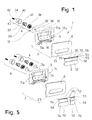
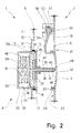
- Number 1 in Figures 1 and 2 indicates as a whole a pneumatic device for controlling a flush tank drain valve, in particular a pneumatic drain valve (known and not shown for the sake of simplicity), which, as is known, is opened by a pneumatic actuating system acting on a movable member of the valve.
- device 1 provides for activating one operating mode of the drain valve (full drainage), so the drain valve associated with device 1 is a single-drain valve.
- Device 1 comprises a supporting structure 2 supporting a button 3 and a pneumatic assembly 4.
- Structure 2 comprises a frame 5 supporting pneumatic assembly 4; and a plate 6 fixable removably to frame 5 and supporting button 3.
- frame 5 comprises a substantially rectangular peripheral border 7 defining an opening 8; and a central portion 9 bridging opening 8 between two opposite sides of border 7.
- border 7 has holes 10 for the insertion of screws by which to fix frame 5 to a wall (e.g. the front wall of the cavity in which the flush tank is housed).
- Portion 9 comprises a plate 11 set back with respect to border 7 and connected to border 7 by two end arms 12; and plate 11 supports three substantially cylindrical seats 13 bounded by respective lateral wall portions 14 projecting perpendicularly from plate 11. More specifically, a central seat 13a and two lateral seats 13b, 13c, located on opposite sides of central seat 13a, are provided; seats 13 are arranged substantially side by side and overlap laterally on plate 11; and each seat 13 comprises a back wall 15, through which a central through hole 16 is formed, and two diametrically opposite retaining seats 17 formed, for example, in lateral wall portions 14 or in back wall 15.
- plate 6 comprises a plate 18, and a peripheral edge 19 substantially perpendicular to plate 18; and plate 18 has a front surface 21, a rear surface 22, and an oblong window 23 formed through plate 18 and bounded by a collar 24 projecting from rear surface 22.
- Structure 2 also comprises reversible fastening means of any known type for fixing plate 6 removably to frame 5.
- the fastening means comprise teeth 26 projecting from rear surface 22 to engage respective seats 27 formed in frame 5; and frame 5 supports elastic members 28, e.g. flexible tongues, which cooperate with peripheral edge 19 of plate 6 to permit engagement of respective seats 27 by teeth 26.
- frame 5 supports one pneumatic assembly 4 housed inside one seat 13, in particular inside central seat 13a.
- pneumatic assembly 4 comprises a casing 30 and an actuator 31; casing 30 is cup-shaped, and comprises a cylindrical inner chamber 32 bounded by a lateral wall 33 and by a back wall 34; actuator 31 comprises a slide 35 housed and sliding inside chamber 32; slide 35 comprises a tubular rod 36 extending axially from a disk 37 fitted to an elastomeric sealing ring 38 which cooperates in sliding manner with lateral wall 33; slide 35 slides axially inside chamber 32 in opposition to a spring 39 interposed between disk 37 and back wall 34; and rod 36 is fitted through hole 16 in seat 13a, and has an end head 40 on the opposite side to disk 37.
- Back wall 34 has an outlet hole 41 engaged by a conduit 42 which is connected in known manner (not shown) to the pneumatic actuating system (known and not shown) of the drain valve; and casing 30 has retaining teeth 43 which cooperate with retaining seats 17 to fix casing 30 to seat 13a, and therefore pneumatic assembly 4 to frame 5.
- Pneumatic assembly 4 may be provided with an optional relief valve 45.
- slide 35 has an inner cylindrical channel 46 housing a pin 47 which slides in opposition to spring 39; and pin 47 has, at one axial end, a shutter 48 loaded by spring 39 and cooperating with disk 37 or sealing ring 38 to close channel 46, and, at the opposite axial end, an end portion 49 projecting axially from head 40.
- Button 3 is a rocking button hinged to plate 6 and housed inside window 23, and comprises a user-operated oblong base portion 52 substantially the same shape as and housed inside window 23; a longitudinal rod 53 parallel to base portion 52; and a brace 54 connecting rod 53 to base portion 52.
- Rod 53 comprises cylindrical pin portions 55; and reinforcing ribbed portions 56 between pin portions 55.
- plate 6 has a number of supports 57 aligned to support button 3 in rotary manner. More specifically, four supports 57 project from rear surface 22 and have respective rotation seats 58 for click-in insertion of respective pin portions 55.
- button 3 contacts actuator 31 directly to cooperate with and exert thrust directly on actuator 31, in particular on head 40, and, if relief valve 45 is provided, on the end portion 49 of pin 47.
- button 3 which is hinged to plate 6 by pin portions 55 inserted inside rotation seats 58, rotation of button 3 causes slide 35 to slide inside chamber 32 and produce an air pulse which is fed along conduit 42 to the pneumatic actuating system to open the drain valve.
- FIG. 5 embodiment shows a two-button control device 1a for selectively activating full or partial drainage; so the drain valve associated with device 1a in this case is a dual-function valve.
- Device 1a comprises supporting structure 2 as described above; two identical pneumatic assemblies 4 identical with that of device 1 described above; and two rocking buttons 3a, 3b hinged to plate 6 and housed side by side inside window 23.
- Each button 3a, 3b comprises a user-operated base portion 52 housed inside window 23; a longitudinal rod 53 parallel to base portion 52; a brace 54 connecting rod 53 to base portion 52; and two cylindrical pin portions 55 at respective opposite axial ends of rod 53 to engage rotation seats 58.
- device 1a comprises the same component parts as device 1 described above, except that the single button 3 is replaced by two buttons 3a, 3b, and two pneumatic assemblies 4 are inserted inside respective seats 13b and 13c.
- Frame 5 in fact, is designed to selectively support one or more pneumatic assemblies 4, and in particular has a number of seats 13 to selectively house one or more pneumatic assemblies 4 inside respective seats 13; and plate 6 also has supports 57 for supporting for rotation one button 3 or two side by side buttons 3a, 3b.
- buttons 3a, 3b cooperate with and exert thrust directly on actuators 31 of respective pneumatic assemblies 4; and the drain valve is activated for full or partial drainage by the user pressing button 3a or 3b.
Landscapes
- Engineering & Computer Science (AREA)
- Mechanical Engineering (AREA)
- Aviation & Aerospace Engineering (AREA)
- Health & Medical Sciences (AREA)
- Life Sciences & Earth Sciences (AREA)
- Hydrology & Water Resources (AREA)
- Public Health (AREA)
- Water Supply & Treatment (AREA)
- Mechanically-Actuated Valves (AREA)
Applications Claiming Priority (2)
| Application Number | Priority Date | Filing Date | Title |
|---|---|---|---|
| ITMI20031323 | 2003-06-27 | ||
| IT001323A ITMI20031323A1 (it) | 2003-06-27 | 2003-06-27 | Dispositivo di comando della valvola di scarico di una cassetta di risciacquo. |
Publications (1)
| Publication Number | Publication Date |
|---|---|
| EP1491690A1 true EP1491690A1 (fr) | 2004-12-29 |
Family
ID=30131319
Family Applications (1)
| Application Number | Title | Priority Date | Filing Date |
|---|---|---|---|
| EP20040102958 Withdrawn EP1491690A1 (fr) | 2003-06-27 | 2004-06-25 | Dispositif de commande pour chasse d'eau |
Country Status (2)
| Country | Link |
|---|---|
| EP (1) | EP1491690A1 (fr) |
| IT (1) | ITMI20031323A1 (fr) |
Cited By (16)
| Publication number | Priority date | Publication date | Assignee | Title |
|---|---|---|---|---|
| DE202006012664U1 (de) * | 2006-08-17 | 2007-12-27 | Viega Gmbh & Co. Kg | Betätigungsvorrichtung für einen Urinal-Unterputzspüler oder WC-Unterputzspülkasten |
| EP2169126A1 (fr) * | 2008-09-29 | 2010-03-31 | Geberit International AG | Dispositif d'actionnement pneumatique |
| ITMI20090339A1 (it) * | 2009-03-06 | 2010-09-07 | Valsir Spa | Assieme placca/controplacca di comando di una cassetta di risciacquo |
| EP2476808A1 (fr) * | 2011-01-14 | 2012-07-18 | Geberit International AG | Dispositif d'actionnement pour une chasse d'eau |
| DE202012002875U1 (de) * | 2012-02-28 | 2013-06-06 | Kai Rettschlag | Universeller Einbau-, Umrüst- u. Reparatursatz für Unterputzspülkästen |
| EP2672030A1 (fr) | 2012-06-08 | 2013-12-11 | Geberit International AG | Dispositif dýactionnement pour un inverseur dýun réservoir de chasse |
| EP2672029A1 (fr) | 2012-06-08 | 2013-12-11 | Geberit International AG | Dispositif d'actionnement pour la soupape d'un réservoir de chasse |
| EP3192931A1 (fr) * | 2016-01-13 | 2017-07-19 | Geberit International AG | Unite d'actionnement |
| ITUA20163286A1 (it) * | 2016-04-20 | 2017-10-20 | Franco Tavarone | Meccanismo cartuccia pneumatica, per sostituzione azionamenti sistemi di risciaquo wc, riparare e migliorare le prestazioni. |
| DE102017123886A1 (de) * | 2017-10-13 | 2019-04-18 | Tece Gmbh | Betätigungstaste für Toilettenspülung |
| RU2771679C1 (ru) * | 2021-08-04 | 2022-05-11 | Виорел Алексеевич Саенко | Встраиваемый узел клавиши смыва инсталляции унитаза |
| EP4095328A1 (fr) * | 2021-05-25 | 2022-11-30 | Kohler (China) Investment Co. Ltd. | Mécanisme de conversion de force de poussée et réservoir chasse d'eau |
| US11927006B2 (en) | 2021-05-25 | 2024-03-12 | Kohler (China) Investment Co., Ltd. | Pushing force converting mechanism and concealed water tank |
| EP4488460A1 (fr) | 2023-07-07 | 2025-01-08 | Geberit International AG | Unité d'actionnement |
| WO2025162597A1 (fr) * | 2024-01-30 | 2025-08-07 | Grohe Ag | Dispositif d'actionnement d'un processus de chasse d'eau de toilette |
| WO2025186053A1 (fr) * | 2024-03-05 | 2025-09-12 | Grohe Ag | Dispositif d'actionnement d'un mécanisme de chasse d'eau de toilettes |
Citations (3)
| Publication number | Priority date | Publication date | Assignee | Title |
|---|---|---|---|---|
| US4304015A (en) * | 1979-06-05 | 1981-12-08 | Geberit Ag | Pneumatic actuating device for a toilet flush valve |
| US4791857A (en) * | 1987-09-17 | 1988-12-20 | Farmer Frederick M | Air valve push button adapter |
| EP0924353A2 (fr) * | 1997-12-15 | 1999-06-23 | Geberit Technik Ag | Dispositif d'actionnement pneumatique d'un réservoir de chasse d'eau |
-
2003
- 2003-06-27 IT IT001323A patent/ITMI20031323A1/it unknown
-
2004
- 2004-06-25 EP EP20040102958 patent/EP1491690A1/fr not_active Withdrawn
Patent Citations (3)
| Publication number | Priority date | Publication date | Assignee | Title |
|---|---|---|---|---|
| US4304015A (en) * | 1979-06-05 | 1981-12-08 | Geberit Ag | Pneumatic actuating device for a toilet flush valve |
| US4791857A (en) * | 1987-09-17 | 1988-12-20 | Farmer Frederick M | Air valve push button adapter |
| EP0924353A2 (fr) * | 1997-12-15 | 1999-06-23 | Geberit Technik Ag | Dispositif d'actionnement pneumatique d'un réservoir de chasse d'eau |
Cited By (19)
| Publication number | Priority date | Publication date | Assignee | Title |
|---|---|---|---|---|
| DE202006012664U1 (de) * | 2006-08-17 | 2007-12-27 | Viega Gmbh & Co. Kg | Betätigungsvorrichtung für einen Urinal-Unterputzspüler oder WC-Unterputzspülkasten |
| EP1889978A2 (fr) | 2006-08-17 | 2008-02-20 | Viega GmbH & Co. KG | Dispositif d'actionnement pour un laveur urinaire encastré ou citerne de laveur encastré pour WC |
| EP1889978A3 (fr) * | 2006-08-17 | 2009-07-22 | Viega GmbH & Co. KG | Dispositif d'actionnement pour un laveur urinaire encastré ou citerne de laveur encastré pour WC |
| EP2169126A1 (fr) * | 2008-09-29 | 2010-03-31 | Geberit International AG | Dispositif d'actionnement pneumatique |
| ITMI20090339A1 (it) * | 2009-03-06 | 2010-09-07 | Valsir Spa | Assieme placca/controplacca di comando di una cassetta di risciacquo |
| EP2226436A1 (fr) * | 2009-03-06 | 2010-09-08 | VALSIR S.p.A. | Ensemble de contreplaque/plaque fonctionnant sur un réservoir de chasse d'eau |
| EP2476808A1 (fr) * | 2011-01-14 | 2012-07-18 | Geberit International AG | Dispositif d'actionnement pour une chasse d'eau |
| DE202012002875U1 (de) * | 2012-02-28 | 2013-06-06 | Kai Rettschlag | Universeller Einbau-, Umrüst- u. Reparatursatz für Unterputzspülkästen |
| EP2672030A1 (fr) | 2012-06-08 | 2013-12-11 | Geberit International AG | Dispositif dýactionnement pour un inverseur dýun réservoir de chasse |
| EP2672029A1 (fr) | 2012-06-08 | 2013-12-11 | Geberit International AG | Dispositif d'actionnement pour la soupape d'un réservoir de chasse |
| EP3192931A1 (fr) * | 2016-01-13 | 2017-07-19 | Geberit International AG | Unite d'actionnement |
| ITUA20163286A1 (it) * | 2016-04-20 | 2017-10-20 | Franco Tavarone | Meccanismo cartuccia pneumatica, per sostituzione azionamenti sistemi di risciaquo wc, riparare e migliorare le prestazioni. |
| DE102017123886A1 (de) * | 2017-10-13 | 2019-04-18 | Tece Gmbh | Betätigungstaste für Toilettenspülung |
| EP4095328A1 (fr) * | 2021-05-25 | 2022-11-30 | Kohler (China) Investment Co. Ltd. | Mécanisme de conversion de force de poussée et réservoir chasse d'eau |
| US11927006B2 (en) | 2021-05-25 | 2024-03-12 | Kohler (China) Investment Co., Ltd. | Pushing force converting mechanism and concealed water tank |
| RU2771679C1 (ru) * | 2021-08-04 | 2022-05-11 | Виорел Алексеевич Саенко | Встраиваемый узел клавиши смыва инсталляции унитаза |
| EP4488460A1 (fr) | 2023-07-07 | 2025-01-08 | Geberit International AG | Unité d'actionnement |
| WO2025162597A1 (fr) * | 2024-01-30 | 2025-08-07 | Grohe Ag | Dispositif d'actionnement d'un processus de chasse d'eau de toilette |
| WO2025186053A1 (fr) * | 2024-03-05 | 2025-09-12 | Grohe Ag | Dispositif d'actionnement d'un mécanisme de chasse d'eau de toilettes |
Also Published As
| Publication number | Publication date |
|---|---|
| ITMI20031323A1 (it) | 2004-12-28 |
| ITMI20031323A0 (it) | 2003-06-27 |
Similar Documents
| Publication | Publication Date | Title |
|---|---|---|
| US8739829B2 (en) | Automatic flush actuation apparatus | |
| RU2434171C2 (ru) | Водопроводный клапан со стержневой ручкой управления | |
| US20080256697A1 (en) | Vacuum Sewer System | |
| EP1945980B1 (fr) | Actionneur de chasse d'eau automatique | |
| US20070102979A1 (en) | Adjustment mechanism for a chair and method for replacing a telescoping cylinder in a reconfigurable chair | |
| PT1898009E (pt) | Dispositivo de acionamento para um objeto sanitário, sobretudo para um autoclismo de wc | |
| JP2530289B2 (ja) | ワンタッチ開閉式バルブ装置 | |
| EP1582637B1 (fr) | Dispositif pour commander la soupape de vidange d'une chasse d'eau et chasse d'eau comprenant un tel dispositif | |
| JP6485631B2 (ja) | 水栓装置 | |
| JP2000160620A (ja) | 遠隔操作式排水装置 | |
| KR100987120B1 (ko) | 스토퍼가 내장되는 도어 | |
| MXPA04006701A (es) | MANGUERA DE REGADERA QUE COMPRENDE UNA VáLVULA DE DOS VIAS, Y LA VáLVULA DE DOS VIAS PARA UNA MANGUERA DE REGADERA. | |
| US8220480B2 (en) | Sanitary fitting | |
| EP2617905A1 (fr) | Ensemble plaque de commande d'un réservoir de chasse d'eau | |
| JP2008130531A (ja) | 押釦構造およびその構造を使用したトイレ用壁付けリモコン | |
| EP1607530A2 (fr) | Dispositif de fixation pour fixer une plaque de commande à un cadre support | |
| DK2672030T3 (en) | Activation device for a drain valve in a rinse tank | |
| CN112136197B (zh) | 转换开关 | |
| NL2030513B1 (en) | Flush plate | |
| KR100760777B1 (ko) | 복귀장치를 구비한 도어 스톱퍼 | |
| JP7626652B2 (ja) | 通水装置 | |
| JP4126181B2 (ja) | 電気錠の切換えレバーと支持枠との構造 | |
| RU2776161C2 (ru) | Переключатель | |
| JP3786246B2 (ja) | 開閉弁 | |
| JP2024168089A (ja) | 切替止水弁 |
Legal Events
| Date | Code | Title | Description |
|---|---|---|---|
| PUAI | Public reference made under article 153(3) epc to a published international application that has entered the european phase |
Free format text: ORIGINAL CODE: 0009012 |
|
| AK | Designated contracting states |
Kind code of ref document: A1 Designated state(s): AT BE BG CH CY CZ DE DK EE ES FI FR GB GR HU IE IT LI LU MC NL PL PT RO SE SI SK TR |
|
| AX | Request for extension of the european patent |
Extension state: AL HR LT LV MK |
|
| AKX | Designation fees paid | ||
| REG | Reference to a national code |
Ref country code: DE Ref legal event code: 8566 |
|
| STAA | Information on the status of an ep patent application or granted ep patent |
Free format text: STATUS: THE APPLICATION IS DEEMED TO BE WITHDRAWN |
|
| 18D | Application deemed to be withdrawn |
Effective date: 20050630 |