EP1494317A1 - Antenne à fente pour véhicules - Google Patents
Antenne à fente pour véhicules Download PDFInfo
- Publication number
- EP1494317A1 EP1494317A1 EP04253859A EP04253859A EP1494317A1 EP 1494317 A1 EP1494317 A1 EP 1494317A1 EP 04253859 A EP04253859 A EP 04253859A EP 04253859 A EP04253859 A EP 04253859A EP 1494317 A1 EP1494317 A1 EP 1494317A1
- Authority
- EP
- European Patent Office
- Prior art keywords
- slot
- conductor
- vehicle
- grounding conductor
- conductor section
- Prior art date
- Legal status (The legal status is an assumption and is not a legal conclusion. Google has not performed a legal analysis and makes no representation as to the accuracy of the status listed.)
- Granted
Links
- 239000004020 conductor Substances 0.000 claims abstract description 144
- 239000000758 substrate Substances 0.000 claims description 13
- 230000035945 sensitivity Effects 0.000 description 13
- 230000005540 biological transmission Effects 0.000 description 11
- 230000005684 electric field Effects 0.000 description 11
- 239000005357 flat glass Substances 0.000 description 6
- 230000001902 propagating effect Effects 0.000 description 4
- 238000013459 approach Methods 0.000 description 3
- 230000003321 amplification Effects 0.000 description 2
- 230000000694 effects Effects 0.000 description 2
- 238000003199 nucleic acid amplification method Methods 0.000 description 2
- 230000005855 radiation Effects 0.000 description 2
- 239000010409 thin film Substances 0.000 description 2
- 230000001154 acute effect Effects 0.000 description 1
- 230000004075 alteration Effects 0.000 description 1
- 230000006735 deficit Effects 0.000 description 1
- 230000001771 impaired effect Effects 0.000 description 1
- 230000002401 inhibitory effect Effects 0.000 description 1
- 125000006850 spacer group Chemical group 0.000 description 1
Images



Classifications
-
- H—ELECTRICITY
- H01—ELECTRIC ELEMENTS
- H01Q—ANTENNAS, i.e. RADIO AERIALS
- H01Q1/00—Details of, or arrangements associated with, antennas
- H01Q1/27—Adaptation for use in or on movable bodies
- H01Q1/32—Adaptation for use in or on road or rail vehicles
- H01Q1/325—Adaptation for use in or on road or rail vehicles characterised by the location of the antenna on the vehicle
- H01Q1/3283—Adaptation for use in or on road or rail vehicles characterised by the location of the antenna on the vehicle side-mounted antennas, e.g. bumper-mounted, door-mounted
-
- H—ELECTRICITY
- H01—ELECTRIC ELEMENTS
- H01Q—ANTENNAS, i.e. RADIO AERIALS
- H01Q1/00—Details of, or arrangements associated with, antennas
- H01Q1/12—Supports; Mounting means
- H01Q1/1271—Supports; Mounting means for mounting on windscreens
-
- H—ELECTRICITY
- H01—ELECTRIC ELEMENTS
- H01Q—ANTENNAS, i.e. RADIO AERIALS
- H01Q13/00—Waveguide horns or mouths; Slot antennas; Leaky-waveguide antennas; Equivalent structures causing radiation along the transmission path of a guided wave
- H01Q13/10—Resonant slot antennas
- H01Q13/106—Microstrip slot antennas
-
- H—ELECTRICITY
- H01—ELECTRIC ELEMENTS
- H01Q—ANTENNAS, i.e. RADIO AERIALS
- H01Q15/00—Devices for reflection, refraction, diffraction or polarisation of waves radiated from an antenna, e.g. quasi-optical devices
- H01Q15/14—Reflecting surfaces; Equivalent structures
-
- H—ELECTRICITY
- H01—ELECTRIC ELEMENTS
- H01Q—ANTENNAS, i.e. RADIO AERIALS
- H01Q23/00—Antennas with active circuits or circuit elements integrated within them or attached to them
Definitions
- the present invention relates to a vehicle-mounted antenna composed of a slot antenna.
- a planar antenna is known in the prior art, for example, that is equipped with a radiating conductor provided on the same surface on the interior side of a vehicle window glass and a roughly loop-shaped grounding conductor that surrounds the periphery of the edge of the radiating conductor at a location away towards the outside from the outer edge of the radiating conductor (see, for example, Japanese Unexamined Patent Application, First Publication No. 2002-252520).
- a planar antenna is known that is equipped with a spacer that inclines the antenna so that the normal direction of the planar antenna approaches the vertical more than the normal direction of the mounting position of the planar antenna (e.g., vehicle window glass) in order to improve the reception sensitivity with respect to signals received from an artificial satellite at a relatively high elevation angle (see, for example, Japanese Unexamined Patent Application, First Publication No. Hei 5-63424).
- planar antenna has been provided on the surface of a vehicle window glass arranged so as to intersect the vertical direction in particular, there is the problem of it being difficult to ensure the desired transmission and reception reliability with respect to vertically polarized waves arriving from the horizontal direction.
- the object of the present invention is to provide a vehicle-mounted antenna capable of inhibiting the loss of installability onto a vehicle while improving transmission and reception characteristics with respect to vertically polarized waves arriving from the horizontal direction.
- a vehicle-mounted antenna includes: a slot antenna equipped with a grounding conductor provided on the surface of a dielectric substrate and a slot formed in the grounding conductor that exposes the surface of the dielectric substrate, and a roughly plate-shaped electrically conductive reflecting member that protrudes from the surface of the grounding conductor at a location close to the slot and forms a predetermined angle with the surface of the grounding conductor.
- the dielectric substrate is made to be the window glass of a vehicle and has a surface that intersects the vertical direction
- the electrically conductive reflecting member that protrudes from the slot antenna formed on the surface of this dielectric substrate so as to form a predetermined angle with this surface
- electric field strength can be relatively increased in a desired region due to the shielding effect of this electrically conductive reflecting member.
- radiation characteristics of the slot antenna in the horizontal direction can be improved, and the sensitivity to vertically polarized waves arriving from the horizontal direction can be improved.
- the grounding conductor may be composed of two conductor sections integrally formed with the location where the slot is formed serving as the border between them, the length of one conductor section in the lengthwise direction of the slot may be formed to be shorter than the length of the other conductor section, and the two conductor sections may be formed in mutually asymmetrical shapes bordering on the slot.
- the grounding conductor being shaped in an asymmetrical shape with the position where the slot is formed in the grounding conductor of the slot antenna serving as a border section, in comparison with, for example, the case in which the grounding conductor is formed into a symmetrical shape, the directional characteristics with respect to vertically polarized waves arriving from the horizontal direction can be set to a shape that more closely approximates non-directivity.
- a vehicle-mounted antenna includes: a slot antenna equipped with a grounding conductor provided on the surface of a dielectric substrate; and a slot formed in the grounding conductor, the slot exposing the surface of the dielectric substrate, wherein the grounding conductor is composed of two conductor sections integrally formed with the location where the slot is formed serving as the border between them, the length of one conductor section in the lengthwise direction of the slot is formed to be shorter than the length of the other conductor section, and the two conductor sections are formed into mutually asymmetrical shapes bordering on the slot.
- the directional characteristics with respect to vertically polarized waves arriving from the horizontal direction can be set to a shape that more closely approaches non-directivity.
- An auxiliary slot may be provided in the grounding conductor that exposes the surface of the dielectric substrate roughly in the shape of the letter "U", the slot may be connected to both ends of the auxiliary slot, and another conductor section may be formed in the grounding conductor of which the peripheries are surrounded by the slot and the auxiliary slot.
- impedance characteristics of the slot antenna can be improved as compared with, for example, the case of not providing the auxiliary slot, and reflection and waveguide characteristics can be improved with respect to vertically polarized waves arriving from the horizontal direction.
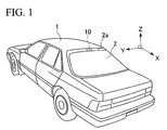
- vehicle-mounted antenna 10 of the present embodiment is arranged on the interior side surface 2A of the periphery 2a of a rear window 2 of the window glasses in a vehicle 1.
- This vehicle-mounted antenna 10 is, for example, an antenna that receives radio waves transmitted from a suitable base station and so forth, and particularly vertically polarized waves arriving from the horizontal direction.
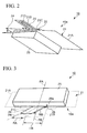
- vehicle-mounted antenna 10 is composed by being provided with a slot antenna 10a, which is composed of a grounding conductor 21 including an electrically conductive thin film and so forth arranged on the interior side surface 2A of rear window 2 serving as a dielectric substrate and a slot 22 formed in grounding conductor 21, an auxiliary slot 23 formed in grounding conductor 21, and a roughly rectangular electrically conductive reflecting plate 24, which protrudes from the surface of grounding conductor 21 at a location close to slot 22 and forms a predetermined angle ⁇ with the surface of grounding conductor 21.
- a slot antenna 10a which is composed of a grounding conductor 21 including an electrically conductive thin film and so forth arranged on the interior side surface 2A of rear window 2 serving as a dielectric substrate and a slot 22 formed in grounding conductor 21, an auxiliary slot 23 formed in grounding conductor 21, and a roughly rectangular electrically conductive reflecting plate 24, which protrudes from the surface of grounding conductor 21 at a location close to slot 22 and forms a predetermined angle ⁇ with the
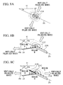
- Grounding conductor 21 is formed by a roughly rectangular first conductor section 21A and a second conductor section 21B composed of an electrically conductive thin film being integrally connected with the location at which a slot 22 to be described later is formed serving as the border between them.
- first conductor section 21A is arranged on the lower side in the vertical direction.
- length LB of second conductor section 21B is formed to be shorter than length LA of first conductor section 21A (LA > LB), and first conductor section 21A and second conductor section 21B are formed mutually asymmetrically bordering on slot 22.
- center line PA of first conductor section 21A which is perpendicular to the lengthwise direction of slot 22 and contains the center position of first conductor 21A
- center line PB of second conductor section 21B which is perpendicular to the lengthwise direction of slot 22 and contains the center position of second conductor section 21B
- first conductor section 21A and second conductor section 21B are, for example, formed in a linearly symmetrical shape with respect to each center line PA and PB.
- a roughly rectangular border conductor section 21C is formed in first conductor 21A at the border between first conductor section 21A and second conductor section 21B, length LC of border conductor section 21C in the lengthwise direction of slot 22 is, for example, formed to be longer than length LB of second conductor section 21B and shorter than length LA of first conductor section 21A (LA > LC > LB), and center line PC of border conductor section 21C, which is perpendicular to the lengthwise direction of slot 22 and contains the center position of border conductor section 21C, and center line PA of first conductor section 21A are formed to be aligned.
- the surface area of second conductor section 21B which is set by length LB of second conductor section 21B in the lengthwise direction of slot 22 and length VB of second conductor section 21B in the direction perpendicular to the lengthwise direction of slot 22 (e.g., LB x VB), is set to change in an increasing trend corresponding to an increase in inclination angle ⁇ relative to horizontal plane H of vehicle interior side surface 2A of rear window 2 (namely, inclination angle ⁇ of the surface of grounding conductor 21 relative to horizontal plane H) as shown in, for example, FIG. 6.
- Slot 22 is composed of a roughly rectangular through hole formed in grounding conductor 21 at the border between first conductor section 21A and second conductor section 21B, and vehicle interior side surface 2A of rear window 2 is exposed through this slot 22.
- An auxiliary slot 23 is composed of a roughly U-shaped through hole formed in second conductor section 21B, and vehicle interior side surface 2A of rear window 2 is exposed through this auxiliary slot 23, and two ends of auxiliary slot 23 are connected to slot 22.
- conductor section 21D is formed in second conductor section 21B, the periphery of which is surrounded by slot 22 and auxiliary slot 23.
- Length SB of auxiliary slot 23 in the lengthwise direction of slot 22 is formed, for example, to be shorter than length LB of second conductor section 21B (LB > SB).
- a power supply point 26 is provided in slot 22 at a location shifted from the center position in the lengthwise direction of slot 22 corresponding to impedance matching and so forth, and as shown, for example, in FIG. 3, this power supply point 26 is connected to, for example, an amplification circuit 25 arranged on the surface of first conductor section 21A via a suitable power supply line 26a, and this amplification circuit 25 is connected, for example, to a transmitter or receiver (not shown).
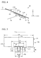
- electrically conductive reflecting plate 24 is arranged so as to protrude in a direction that forms a predetermined angle ⁇ with respect to the surface of grounding conductor 21 so as to have a downward slope towards the front of the vehicle from a location shifted downward in the vertical direction (in other words, towards the rear of the vehicle) from slot 22 on the surface of grounding conductor 21.
- center line PR of electrically conductive reflecting plate 24, which is perpendicular to the lengthwise direction of slot 22 and contains the center position of electrically conductive reflecting plate 24, intersects with any of the directions in which each center line PA, PB and PC of each conductor section 21A, 21B and 21C extends that faces upward in the vertical direction (in other words, towards the front of the vehicle) at a predetermined angle ⁇ , and this predetermined angle ⁇ is set to be larger than, for example, inclination angle ⁇ of the surface of grounding conductor 21 with respect to horizontal plane H.
- length RB of electrically conductive reflecting plate 24 in the direction perpendicular to the lengthwise direction of slot 22 is set so as to change in an increasing trend corresponding to an increase in inclination angle ⁇ of the surface of grounding conductor 21 with respect to horizontal plane H.
- length RB of electrically conductive reflecting plate 24 in the direction perpendicular to the lengthwise direction of slot 22 is set to a suitable dimension of about ⁇ /4 or less.
- the angle formed between electrically conductive reflecting plate 24 and grounding conductor 21, namely predetermined angle ⁇ , is set to as to change in an increasing trend corresponding to an increase in inclination angle ⁇ of the surface of grounding conductor 21 with respect to horizontal plane H.
- the vehicle-mounted antenna 10 according to the present embodiment is provided with the aforementioned constitution, and the following provides an explanation of the operating characteristics of this vehicle-mounted antenna 10 with reference to the attached drawings.
- electrically conductive reflecting plate 24 is made to protrude from a location shifted downward in the vertical direction (namely, towards the rear of the vehicle) from slot 22 on the surface of first conductor section 21A so as to form a predetermined angle ⁇ with respect to the direction extending upward in the vertical direction (namely, towards the front of the vehicle) of center line PA of first conductor section 21A and have a downward slope towards the front of the vehicle, transmission and reception sensitivity with respect to vertically polarized wave components propagating in the horizontal direction can be improved.
- the direction characteristics ⁇ in the case of being provided with electrically conductive reflecting plate 24 are such that the gain in the forward direction of the vehicle in which electrically conductive reflecting plate 24 protrudes increases as compared with the directional characteristics ⁇ in the case of omitting electrically conductive reflecting plate 24.
- second conductor section 21B having a different shape than first conductor section 21A is provided so as to form a predetermined angle ⁇ with electrically conductive reflecting plate 24 in the direction extending upward in the vertical direction (namely, towards the front of the vehicle) of center line PA of first conductor section 21A, transmission and reception sensitivity with respect to vertically polarized wave components propagating from the horizontal direction can be further improved.
- the electric field distribution of region C and region A, in which the angle formed by second conductor section 21B and first conductor section 21A is ⁇ (180°) is formed more preferably.
- directional characteristic y in the case of providing electrically conductive reflecting plate 24 and second conductor section 21B is such that together with gain in all directions within the horizontal plane increasing as compared with direction characteristic ⁇ in the case of providing only electrically conductive reflecting plate 24, the gain becomes nearly equal in all directions, resulting in a so-called non-directional state.
- a change in the sensitivity, or gain, with respect to vertically polarized wave components of this vehicle-mounted antenna 10 corresponding to the frequency of the mean value (mean gain) dBa around the vertical axis (Z axis shown in FIG. 1), is a value larger than a predetermined lower limit mean gain dB, and this can be understood to make it possible to secure desired transmission and reception sensitivity with respect to vertically polarized wave components.
- auxiliary slot 23 in second conductor section 21B, impedance characteristics are improved as compared with the case of, for example, omitting auxiliary slot 23, and this can be understood to be able to lower the standing wave ratio (SWR).
- SWR standing wave ratio
- a vehicle-mounted antenna 10 According to a vehicle-mounted antenna 10 according to the present embodiment, radiation characteristics in the horizontal direction of slot antenna 10a can be improved by providing electrically conductive reflecting plate 24, thereby making it possible to improve sensitivity with respect to vertically polarized waves arriving from the horizontal direction.
- electrically conductive reflecting plate 24 can be reduced in the state in which a desired transmission and reception sensitivity with respect to vertically polarized waves has been secured, the field of view of vehicle passengers from being obstructed can be prevented, and also impairment of vehicle appearance can be prevented.
- grounding conductor 21 an asymmetrical shape bordering at the location where slot 22 is formed in grounding conductor 21
- impedance characteristics can be improved, and the transmission and reception sensitivity with respect to vertically polarized waves arriving from the horizontal direction can be improved, and also the directional characteristics with respect to vertically polarized waves arriving from the horizontal direction can be set to have a shape that more closely approaches non-directivity.
- impedance characteristics can be further improved by forming a roughly U-shaped auxiliary slot in second conductor section 21B, and connecting both ends of auxiliary slot 23 to slot 22.
- first conductor section 21A and second conductor section 21B may be formed to have an equal length, and first conductor section 21A and second conductor section 21B may be formed symmetrically with slot 22 being the border between them.
- center line PA of first conductor section 21A and center line PB of second conductor section 21B were made to be aligned in the lengthwise direction of slot 22 in the aforementioned present embodiment, the present invention is not limited to this, but rather center line PA and center line PB may be, for example, set to be shifted out of alignment in the lengthwise direction of slot 22.
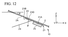
- electrically conductive reflecting plate 24 is made to protrude from a location shifted downward in the vertical direction (namely, towards the rear of the vehicle) from slot 22 on the surface of grounding conductor 21 in the aforementioned present embodiment, the present invention is not limited to this, but rather as shown, for example, in FIG. 12, electrically conductive reflecting plate 24 may be arranged so as to protrude from a location shifted upward in the vertical direction (namely, towards the front of the vehicle) from slot 22.
- center line PR of electrically conductive reflecting plate 24 was made to intersect with center line PA of first conductor section 21A, center line PB of second conductor section 21B and center line PC of border conductor section 21C in the aforementioned present embodiment, the present invention is not limited to this, but rather, for example, center line PR of electrically conductive reflecting plate 24 may be set so as to not intersect each center line PA, PB and PC, but instead contain locations shifted from each center line PC, PB and PC in the lengthwise direction of slot 22.
- first conductor section 21A and the second conductor section 21B correspond to "conductor section” described in claim of the present invention
- the conductor 21D corresponds to "another conductor section” described in claim of the present invention.
Landscapes
- Engineering & Computer Science (AREA)
- Remote Sensing (AREA)
- Physics & Mathematics (AREA)
- Electromagnetism (AREA)
- Waveguide Aerials (AREA)
- Aerials With Secondary Devices (AREA)
- Details Of Aerials (AREA)
- Support Of Aerials (AREA)
Applications Claiming Priority (2)
| Application Number | Priority Date | Filing Date | Title |
|---|---|---|---|
| JP2003187303A JP4021814B2 (ja) | 2003-06-30 | 2003-06-30 | 車載アンテナ |
| JP2003187303 | 2003-06-30 |
Publications (2)
| Publication Number | Publication Date |
|---|---|
| EP1494317A1 true EP1494317A1 (fr) | 2005-01-05 |
| EP1494317B1 EP1494317B1 (fr) | 2007-04-18 |
Family
ID=33432255
Family Applications (1)
| Application Number | Title | Priority Date | Filing Date |
|---|---|---|---|
| EP04253859A Expired - Lifetime EP1494317B1 (fr) | 2003-06-30 | 2004-06-28 | Antenne à fente pour véhicules |
Country Status (4)
| Country | Link |
|---|---|
| US (1) | US7088295B2 (fr) |
| EP (1) | EP1494317B1 (fr) |
| JP (1) | JP4021814B2 (fr) |
| DE (1) | DE602004005925T2 (fr) |
Cited By (2)
| Publication number | Priority date | Publication date | Assignee | Title |
|---|---|---|---|---|
| DE102011076246A1 (de) | 2011-05-20 | 2012-11-22 | Antonics-Icp Gmbh | Mehrbandfähige Anordnung für Funksignale und Verfahren zur Herstellung einer zugehörigen Erregerstruktur |
| CN102856635A (zh) * | 2011-06-27 | 2013-01-02 | 旭丽电子(广州)有限公司 | 多频天线及具有该多频天线的电子装置 |
Families Citing this family (7)
| Publication number | Priority date | Publication date | Assignee | Title |
|---|---|---|---|---|
| JP4407617B2 (ja) * | 2005-10-20 | 2010-02-03 | 株式会社デンソー | 無線通信システム |
| GB0922191D0 (en) * | 2009-12-21 | 2010-02-03 | Pilkington Group Ltd | Vehicle glazing |
| KR101801186B1 (ko) * | 2011-02-25 | 2017-11-24 | 엘지전자 주식회사 | 이동 단말기 |
| US10439275B2 (en) | 2016-06-24 | 2019-10-08 | Ford Global Technologies, Llc | Multiple orientation antenna for vehicle communication |
| CN111987408B (zh) * | 2020-08-21 | 2021-10-19 | 福耀玻璃工业集团股份有限公司 | 天线结构、天线玻璃组件及交通工具 |
| US11652290B2 (en) | 2021-08-23 | 2023-05-16 | GM Global Technology Operations LLC | Extremely low profile ultra wide band antenna |
| US11901616B2 (en) * | 2021-08-23 | 2024-02-13 | GM Global Technology Operations LLC | Simple ultra wide band very low profile antenna arranged above sloped surface |
Citations (7)
| Publication number | Priority date | Publication date | Assignee | Title |
|---|---|---|---|---|
| EP0378905A1 (fr) * | 1988-12-16 | 1990-07-25 | The Marconi Company Limited | Antenne microbande couplée par une fente et réseau d'antennes à commande de phase comportant de telles antennes |
| US6188369B1 (en) * | 1997-05-30 | 2001-02-13 | Hitachi, Ltd. | Tunable slot antenna with capacitively coupled slot island conductor for precise impedance adjustment |
| EP1128467A2 (fr) * | 2000-02-22 | 2001-08-29 | SMARTEQ Wireless AB | Dispositif d'antenne |
| US6342864B1 (en) * | 1999-07-19 | 2002-01-29 | Kokusai Electric Co., Ltd. | Slot array antenna with cavities |
| US6404394B1 (en) * | 1999-12-23 | 2002-06-11 | Tyco Electronics Logistics Ag | Dual polarization slot antenna assembly |
| US20020175864A1 (en) * | 2001-05-22 | 2002-11-28 | Acer Neweb Cprp. | Space diversity slot antennas and apparatus using the same |
| US20030043083A1 (en) * | 2001-08-29 | 2003-03-06 | Huang Chien Shun | Slot antenna having irregular geometric shape |
Family Cites Families (8)
| Publication number | Priority date | Publication date | Assignee | Title |
|---|---|---|---|---|
| JPH0563424A (ja) | 1991-08-30 | 1993-03-12 | Asahi Glass Co Ltd | 高周波用アンテナ |
| WO1999028990A1 (fr) * | 1997-12-01 | 1999-06-10 | Kabushiki Kaisha Toshiba | Antenne de type f inversee pour frequences multiples |
| AU2001280076B2 (en) * | 2000-08-28 | 2007-04-05 | In4Tel Ltd. | Apparatus and method for enhancing low-frequency operation of mobile communication antennas |
| JP2002252520A (ja) | 2001-02-22 | 2002-09-06 | Asahi Glass Co Ltd | 平面アンテナ |
| US6466170B2 (en) * | 2001-03-28 | 2002-10-15 | Motorola, Inc. | Internal multi-band antennas for mobile communications |
| US6879296B2 (en) * | 2001-11-21 | 2005-04-12 | Superpass Company Inc. | Horizontally polarized slot antenna with omni-directional and sectorial radiation patterns |
| JP3656610B2 (ja) * | 2002-03-27 | 2005-06-08 | 日立電線株式会社 | 板状アンテナおよびそれを備えた電気機器 |
| JP2005012588A (ja) * | 2003-06-20 | 2005-01-13 | Nippon Sheet Glass Co Ltd | 車両用ガラスアンテナ装置 |
-
2003
- 2003-06-30 JP JP2003187303A patent/JP4021814B2/ja not_active Expired - Fee Related
-
2004
- 2004-06-28 DE DE602004005925T patent/DE602004005925T2/de not_active Expired - Fee Related
- 2004-06-28 EP EP04253859A patent/EP1494317B1/fr not_active Expired - Lifetime
- 2004-06-28 US US10/876,757 patent/US7088295B2/en not_active Expired - Fee Related
Patent Citations (7)
| Publication number | Priority date | Publication date | Assignee | Title |
|---|---|---|---|---|
| EP0378905A1 (fr) * | 1988-12-16 | 1990-07-25 | The Marconi Company Limited | Antenne microbande couplée par une fente et réseau d'antennes à commande de phase comportant de telles antennes |
| US6188369B1 (en) * | 1997-05-30 | 2001-02-13 | Hitachi, Ltd. | Tunable slot antenna with capacitively coupled slot island conductor for precise impedance adjustment |
| US6342864B1 (en) * | 1999-07-19 | 2002-01-29 | Kokusai Electric Co., Ltd. | Slot array antenna with cavities |
| US6404394B1 (en) * | 1999-12-23 | 2002-06-11 | Tyco Electronics Logistics Ag | Dual polarization slot antenna assembly |
| EP1128467A2 (fr) * | 2000-02-22 | 2001-08-29 | SMARTEQ Wireless AB | Dispositif d'antenne |
| US20020175864A1 (en) * | 2001-05-22 | 2002-11-28 | Acer Neweb Cprp. | Space diversity slot antennas and apparatus using the same |
| US20030043083A1 (en) * | 2001-08-29 | 2003-03-06 | Huang Chien Shun | Slot antenna having irregular geometric shape |
Cited By (3)
| Publication number | Priority date | Publication date | Assignee | Title |
|---|---|---|---|---|
| DE102011076246A1 (de) | 2011-05-20 | 2012-11-22 | Antonics-Icp Gmbh | Mehrbandfähige Anordnung für Funksignale und Verfahren zur Herstellung einer zugehörigen Erregerstruktur |
| DE202011110175U1 (de) | 2011-05-20 | 2013-03-21 | Antonics-Icp Gmbh | Mehrbandfähige Anordnung für Funksignale |
| CN102856635A (zh) * | 2011-06-27 | 2013-01-02 | 旭丽电子(广州)有限公司 | 多频天线及具有该多频天线的电子装置 |
Also Published As
| Publication number | Publication date |
|---|---|
| JP4021814B2 (ja) | 2007-12-12 |
| EP1494317B1 (fr) | 2007-04-18 |
| US7088295B2 (en) | 2006-08-08 |
| US20050007284A1 (en) | 2005-01-13 |
| DE602004005925T2 (de) | 2008-01-17 |
| JP2005026783A (ja) | 2005-01-27 |
| DE602004005925D1 (de) | 2007-05-31 |
Similar Documents
| Publication | Publication Date | Title |
|---|---|---|
| CN112771719B (zh) | 天线系统 | |
| US8941545B2 (en) | Windowpane for vehicle and antenna | |
| JP3285299B2 (ja) | 小型アンテナおよび光ビーコン、電波ビーコン共用車載フロントエンド | |
| EP1437792B1 (fr) | Antenne fente à cavité | |
| US20010015703A1 (en) | Antenna device and an antenna assembly | |
| EP1434301B1 (fr) | Antenne montée sur une vitre d'un véhicule | |
| US7126539B2 (en) | Non-uniform dielectric beam steering antenna | |
| US20180115048A1 (en) | Vehicle antenna and window glass | |
| US7289075B2 (en) | Planar antenna | |
| JPH11330842A (ja) | 広帯域アンテナ | |
| EP1494317B1 (fr) | Antenne à fente pour véhicules | |
| US6222497B1 (en) | Antenna device | |
| US20230253712A1 (en) | Antenna device for vehicle | |
| US7019699B2 (en) | On-board antenna | |
| JP2002252520A (ja) | 平面アンテナ | |
| US6930645B2 (en) | Automotive on-board antenna | |
| JP7734492B2 (ja) | パッチアンテナ | |
| US7199758B2 (en) | Antenna device | |
| US6995722B2 (en) | On-board antenna | |
| US20070080876A1 (en) | Planar antenna and window glass sheet for automobiles | |
| US12586890B2 (en) | Antenna device and vehicle including the same | |
| JP4649371B2 (ja) | 車載用アンテナ装置 |
Legal Events
| Date | Code | Title | Description |
|---|---|---|---|
| PUAI | Public reference made under article 153(3) epc to a published international application that has entered the european phase |
Free format text: ORIGINAL CODE: 0009012 |
|
| AK | Designated contracting states |
Kind code of ref document: A1 Designated state(s): AT BE BG CH CY CZ DE DK EE ES FI FR GB GR HU IE IT LI LU MC NL PL PT RO SE SI SK TR |
|
| AX | Request for extension of the european patent |
Extension state: AL HR LT LV MK |
|
| RIN1 | Information on inventor provided before grant (corrected) |
Inventor name: FUKUMARU, TOMOYUKIK.K. HON-DA GIJUTSU KENKYUSHO Inventor name: MATSUSHITA, TATSUOC/O NIPPON SHEET GLASS CO., LTD Inventor name: KURIBAYASHI, HIROSHIK.K. HON-DA GIJUTSU KENKYUSHO Inventor name: IIJIMA, HIROSHIC/O NIPPON SHEET GLASS CO., LTD. Inventor name: OSHIMA, HIDEAKIC/O NIPPON SHEET GLASS CO., LTD. Inventor name: KOMATSU, SATORUC/O K.K. HON-DA GIJUTSU KENKYUSHO |
|
| 17P | Request for examination filed |
Effective date: 20050518 |
|
| AKX | Designation fees paid |
Designated state(s): DE FR GB |
|
| GRAP | Despatch of communication of intention to grant a patent |
Free format text: ORIGINAL CODE: EPIDOSNIGR1 |
|
| GRAS | Grant fee paid |
Free format text: ORIGINAL CODE: EPIDOSNIGR3 |
|
| GRAA | (expected) grant |
Free format text: ORIGINAL CODE: 0009210 |
|
| AK | Designated contracting states |
Kind code of ref document: B1 Designated state(s): DE FR GB |
|
| REF | Corresponds to: |
Ref document number: 602004005925 Country of ref document: DE Date of ref document: 20070531 Kind code of ref document: P |
|
| ET | Fr: translation filed | ||
| PLBE | No opposition filed within time limit |
Free format text: ORIGINAL CODE: 0009261 |
|
| STAA | Information on the status of an ep patent application or granted ep patent |
Free format text: STATUS: NO OPPOSITION FILED WITHIN TIME LIMIT |
|
| 26N | No opposition filed |
Effective date: 20080121 |
|
| PGFP | Annual fee paid to national office [announced via postgrant information from national office to epo] |
Ref country code: DE Payment date: 20080627 Year of fee payment: 5 |
|
| PGFP | Annual fee paid to national office [announced via postgrant information from national office to epo] |
Ref country code: FR Payment date: 20080625 Year of fee payment: 5 |
|
| PGFP | Annual fee paid to national office [announced via postgrant information from national office to epo] |
Ref country code: GB Payment date: 20080618 Year of fee payment: 5 |
|
| GBPC | Gb: european patent ceased through non-payment of renewal fee |
Effective date: 20090628 |
|
| REG | Reference to a national code |
Ref country code: FR Ref legal event code: ST Effective date: 20100226 |
|
| PG25 | Lapsed in a contracting state [announced via postgrant information from national office to epo] |
Ref country code: FR Free format text: LAPSE BECAUSE OF NON-PAYMENT OF DUE FEES Effective date: 20090630 |
|
| PG25 | Lapsed in a contracting state [announced via postgrant information from national office to epo] |
Ref country code: GB Free format text: LAPSE BECAUSE OF NON-PAYMENT OF DUE FEES Effective date: 20090628 |
|
| PG25 | Lapsed in a contracting state [announced via postgrant information from national office to epo] |
Ref country code: DE Free format text: LAPSE BECAUSE OF NON-PAYMENT OF DUE FEES Effective date: 20100101 |