EP1496257A2 - Pompe à rotors à vis - Google Patents
Pompe à rotors à vis Download PDFInfo
- Publication number
- EP1496257A2 EP1496257A2 EP04012939A EP04012939A EP1496257A2 EP 1496257 A2 EP1496257 A2 EP 1496257A2 EP 04012939 A EP04012939 A EP 04012939A EP 04012939 A EP04012939 A EP 04012939A EP 1496257 A2 EP1496257 A2 EP 1496257A2
- Authority
- EP
- European Patent Office
- Prior art keywords
- spindle
- spindles
- screw pump
- elastic layer
- top surfaces
- Prior art date
- Legal status (The legal status is an assumption and is not a legal conclusion. Google has not performed a legal analysis and makes no representation as to the accuracy of the status listed.)
- Granted
Links
Images

Classifications
-
- F—MECHANICAL ENGINEERING; LIGHTING; HEATING; WEAPONS; BLASTING
- F04—POSITIVE - DISPLACEMENT MACHINES FOR LIQUIDS; PUMPS FOR LIQUIDS OR ELASTIC FLUIDS
- F04C—ROTARY-PISTON, OR OSCILLATING-PISTON, POSITIVE-DISPLACEMENT MACHINES FOR LIQUIDS; ROTARY-PISTON, OR OSCILLATING-PISTON, POSITIVE-DISPLACEMENT PUMPS
- F04C2/00—Rotary-piston machines or pumps
- F04C2/08—Rotary-piston machines or pumps of intermeshing-engagement type, i.e. with engagement of co-operating members similar to that of toothed gearing
- F04C2/12—Rotary-piston machines or pumps of intermeshing-engagement type, i.e. with engagement of co-operating members similar to that of toothed gearing of other than internal-axis type
- F04C2/14—Rotary-piston machines or pumps of intermeshing-engagement type, i.e. with engagement of co-operating members similar to that of toothed gearing of other than internal-axis type with toothed rotary pistons
- F04C2/16—Rotary-piston machines or pumps of intermeshing-engagement type, i.e. with engagement of co-operating members similar to that of toothed gearing of other than internal-axis type with toothed rotary pistons with helical teeth, e.g. chevron-shaped, screw type
- F04C2/165—Rotary-piston machines or pumps of intermeshing-engagement type, i.e. with engagement of co-operating members similar to that of toothed gearing of other than internal-axis type with toothed rotary pistons with helical teeth, e.g. chevron-shaped, screw type having more than two rotary pistons with parallel axes
-
- F—MECHANICAL ENGINEERING; LIGHTING; HEATING; WEAPONS; BLASTING
- F04—POSITIVE - DISPLACEMENT MACHINES FOR LIQUIDS; PUMPS FOR LIQUIDS OR ELASTIC FLUIDS
- F04C—ROTARY-PISTON, OR OSCILLATING-PISTON, POSITIVE-DISPLACEMENT MACHINES FOR LIQUIDS; ROTARY-PISTON, OR OSCILLATING-PISTON, POSITIVE-DISPLACEMENT PUMPS
- F04C2/00—Rotary-piston machines or pumps
- F04C2/08—Rotary-piston machines or pumps of intermeshing-engagement type, i.e. with engagement of co-operating members similar to that of toothed gearing
- F04C2/082—Details specially related to intermeshing engagement type machines or pumps
- F04C2/084—Toothed wheels
-
- F—MECHANICAL ENGINEERING; LIGHTING; HEATING; WEAPONS; BLASTING
- F04—POSITIVE - DISPLACEMENT MACHINES FOR LIQUIDS; PUMPS FOR LIQUIDS OR ELASTIC FLUIDS
- F04C—ROTARY-PISTON, OR OSCILLATING-PISTON, POSITIVE-DISPLACEMENT MACHINES FOR LIQUIDS; ROTARY-PISTON, OR OSCILLATING-PISTON, POSITIVE-DISPLACEMENT PUMPS
- F04C2230/00—Manufacture
- F04C2230/90—Improving properties of machine parts
- F04C2230/91—Coating
-
- F—MECHANICAL ENGINEERING; LIGHTING; HEATING; WEAPONS; BLASTING
- F05—INDEXING SCHEMES RELATING TO ENGINES OR PUMPS IN VARIOUS SUBCLASSES OF CLASSES F01-F04
- F05C—INDEXING SCHEME RELATING TO MATERIALS, MATERIAL PROPERTIES OR MATERIAL CHARACTERISTICS FOR MACHINES, ENGINES OR PUMPS OTHER THAN NON-POSITIVE-DISPLACEMENT MACHINES OR ENGINES
- F05C2225/00—Synthetic polymers, e.g. plastics; Rubber
- F05C2225/02—Rubber
Definitions
- the invention relates to a screw pump - for Delivery of a flow medium - with in a pump housing provided drive spindles flanked by running spindles, where the spindle threads of the spindles touch.
- the shape of a drive spindle is for example the To refer font to DE 92 11 523 of the Applicant with at a spindle shaft coaxially adjoining spindle section, whose circumference is determined by tooth flanks.
- the spindles are at least partially with an elastic layer provided, which preferably consists of a Elastomer exists.
- This - for example, vulcanized - Layer should have a dampening effect and a suitable one Have thickness; the latter must ensure that a Pressing between the spindles on this coated Jobs can be sustained so that a permanent Walk work on these layers can take place.
- this flexing work is in this embodiment a certain degree the occurring torsional vibration and Axialschwingungsenergie consumed and thus dampened, so that the vibrational energy is no longer in its entirety Gear mesh contact destroyed as well as the wear attack is reduced.
- the elastic Layer formed as a cup-shaped part and on a Spindle end pushed on.
- the layer on a screw pump with - optionally cross-sectionally part-circular curved - Top surfaces of the spindle threads is the elastic layer cup-like attached to those head surfaces of the spindle threads; the other spindle areas remain layer-free.
- a further embodiment of the screw pump optionally has cross-sectionally part-circular curved Top surfaces of the spindle threads and between the top surfaces extending side surfaces of the spindle; inventively are both the top surfaces of the spindle gear as well as the side surfaces of the spindle with the elastic Covered layer; the latter gives a closed sleeve-like Serving. All meshed surfaces are coated to a limited length; the highest degree of flexing work must be done here and will therefore offer the highest damping effect.
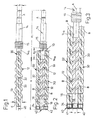
- screw pump has in the interior a pump housing on a drive spindle 10, which is flanked by two sealing or running spindles 30.
- the Longitudinal axes A and B of the drive spindle 10 and the Both spindles 30 are parallel to each other.
- the drive spindle 10 has a metallic spindle body 12 of a length a to the right in Fig. 1 to 3 pressure side a coaxial - cross-sectionally multi-stepped - spindle shaft 14 of diameter b with a - Drollenuten offering - compensating piston 15. This is in the installed position on the inside - not recognizable - a flange or an end wall of that pump housing. From the compensating piston 15 goes to the spindle body 12 toward a coaxial shaft portion 14 a of the diameter b 1 .
- the diameter d of the spindle body 12 is in the rest of a spirally arranged spindle gear 33 of the drive spindle 10 determines that with appropriate metallic Spindle gears 33 of the spindles 30 meshes.
- suction side - cylindrically shaped - shaft end 16 with cylindrical end pin 18 of the drive spindle 10 is located between on both sides adjacent end portions of the Dichtoder Running spindle 30, and these in turn each with a cylindrical end journal 34.
- end pins 18, 34 are shown in FIG. 5 in a common plane E.
- the end pins 34 of the sealing and running spindles 30 and the End pins 18 of the drive spindle 10 are of the same Diameter c and each of a tube tap 40 made of flexible Material of length q covered, the endwards through a molded cup bottom 41 is closed; with each other aligned cup bases 42 each span the free end 19 and 35 of the associated spigot 18th or 34.
- the Napfböden 42 on the spindles 30 are according to Fig. 2, 3 provided with diametrically molded inner ribs 42 and push with their comb to the subsequent forehead 35.
- tube cups 40 roll off one another and, as shown in FIG. 5, are temporarily deformed on both sides of the central spigot 18 and on both sides of that plane E (panel S); the cross-sectional mid-axes M of the two end pins 34 of the spindles 30 are displaced from their rest positions M r to the central end pin 18 in this deformation process.
- a milling operation is changed which changes the spindle position.
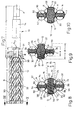
- Fig. 8 illustrates the transverse axis Q symmetrical cross section of the spindle set of Fig. 7 shows an embodiment of the spindle body 12, which consists of a central portion 20 circular outer contour of the diameter d 1 and two - lying in that transverse axis Q - projections 22 approximately oval design composed as a spindle profile; FIG. 8 also illustrates that the height h of these projections 22 is shorter than the central spindle diameter d 1 .
- two axially parallel shaft stubs 31 of the spindles 30 run.
- the latter is - as possibly also the above-described pipe cup 40 - formed from an elastomer; This material must be chemically resistant, especially with regard to emulsions, oil or water.
- the likewise part-circular outer surface 52 of the layer 50 extends in a circular contour K 1 ; whose distance from the adjacent circle contour K determines the layer thickness z.
- Each running spindle 30 is determined cross-sectionally by a circular contour N of the diameter e, which here depends on the circumference of the tooth flanks or of the spindle passage 33.
- the barrel spindle 30 has a - in the sketched in Fig. 8 to 10 position a common center axis T determining - I-shaped cross-section on with a web portion 36, which merges into integrally formed head extensions 38 at both ends; the cross-sectional shape of the tooth flanks or top surfaces 39 are determined by that circular contour N and are therefore each designed cross-sectionally part-circular.
- the top surfaces 39 are respectively spanned by a layer 54, which is likewise formed of elastomeric material, whose outer surface 56 lies in a circular contour N 1 .
- the radial contour spacing determines the thickness y of the layer 54.
- Fig. 9 are those top surfaces 23 of the projections 22 of the drive spindle 10 free, however the between these cross-sectional side surfaces 24 of the projections 22 and the central portion 20 each of a layer or Walk layer 26th covered; the latter contains - corresponding to the spindle cross-section - Cross-sectionally three trough-shaped curved Sections.
- the spindles 30 here wear flank layers or shells 58 on the side surfaces 37 of the land areas 36.
- this embodiment is therefore on the - the Fig. 9 corresponding - same length section the Walk layer but in the tooth flanks 13, 33 of all three Spindles 10, 30 and the core diameter of the drive spindle 10 applied.
- the outside diameters are not coated. This is in three-dimensional direction flexing made in a higher degree and the damping effect is in to be expected to a greater extent than in the embodiment of FIG. 9th
- Fig. 10 in each case entirely of a closed Layer or shell 28 or 60 of elastomeric Material embraced drive and running spindles 10 and 30; it is all meshed surfaces on one limited length coated. This must be the highest degree be done on flexing work, and is therefore with the offer the highest damping effect.
Landscapes
- Engineering & Computer Science (AREA)
- Mechanical Engineering (AREA)
- General Engineering & Computer Science (AREA)
- Rotary Pumps (AREA)
- Details And Applications Of Rotary Liquid Pumps (AREA)
- Screw Conveyors (AREA)
Applications Claiming Priority (4)
| Application Number | Priority Date | Filing Date | Title |
|---|---|---|---|
| DE20310651 | 2003-07-10 | ||
| DE20310651U | 2003-07-10 | ||
| DE20313288U | 2003-08-26 | ||
| DE20313288 | 2003-08-26 |
Publications (3)
| Publication Number | Publication Date |
|---|---|
| EP1496257A2 true EP1496257A2 (fr) | 2005-01-12 |
| EP1496257A3 EP1496257A3 (fr) | 2005-08-17 |
| EP1496257B1 EP1496257B1 (fr) | 2007-07-18 |
Family
ID=32109020
Family Applications (1)
| Application Number | Title | Priority Date | Filing Date |
|---|---|---|---|
| EP04012939A Expired - Lifetime EP1496257B1 (fr) | 2003-07-10 | 2004-05-29 | Pompe à rotors à vis |
Country Status (3)
| Country | Link |
|---|---|
| EP (1) | EP1496257B1 (fr) |
| AT (1) | ATE367528T1 (fr) |
| DE (2) | DE20318594U1 (fr) |
Cited By (2)
| Publication number | Priority date | Publication date | Assignee | Title |
|---|---|---|---|---|
| CN106640628A (zh) * | 2016-10-09 | 2017-05-10 | 广东技术师范学院 | 微啮合间隙高压螺杆泵 |
| DE102018103446A1 (de) * | 2018-02-15 | 2019-08-22 | Michael Schröter | Vorrichtung und Verfahren zum Verdichten und/oder Verdrängen eines Fluids |
Families Citing this family (2)
| Publication number | Priority date | Publication date | Assignee | Title |
|---|---|---|---|---|
| DE102018222516A1 (de) | 2018-12-20 | 2020-06-25 | Audi Ag | Antriebseinrichtung für ein Kraftfahrzeug |
| DE102022207330A1 (de) * | 2022-07-19 | 2024-01-25 | Vitesco Technologies GmbH | Spindelpumpenstufe, Fluidfördervorrichtung und Kraftfahrzeug |
Family Cites Families (4)
| Publication number | Priority date | Publication date | Assignee | Title |
|---|---|---|---|---|
| CH232200A (de) * | 1942-03-09 | 1944-05-15 | Fried Krupp Germaniawerft Akti | Schraubenpumpe. |
| JPS58148292A (ja) * | 1982-02-26 | 1983-09-03 | Hitachi Ltd | スクリユ−圧縮機のロ−タ表面処理 |
| SU1437575A1 (ru) * | 1987-03-17 | 1988-11-15 | И.М.Чесноков и А.И.Чеснаков | Двухвинтовой растворонасос |
| JPH03290086A (ja) * | 1990-04-06 | 1991-12-19 | Hitachi Ltd | スクリュ式回転機械と該機械のロータ表面処理方法およびドライ方式のスクリュ式回転機械と該機械のロータ表面処理方法 |
-
2003
- 2003-12-02 DE DE20318594U patent/DE20318594U1/de not_active Expired - Lifetime
-
2004
- 2004-05-29 DE DE502004004339T patent/DE502004004339D1/de not_active Expired - Lifetime
- 2004-05-29 EP EP04012939A patent/EP1496257B1/fr not_active Expired - Lifetime
- 2004-05-29 AT AT04012939T patent/ATE367528T1/de active
Cited By (2)
| Publication number | Priority date | Publication date | Assignee | Title |
|---|---|---|---|---|
| CN106640628A (zh) * | 2016-10-09 | 2017-05-10 | 广东技术师范学院 | 微啮合间隙高压螺杆泵 |
| DE102018103446A1 (de) * | 2018-02-15 | 2019-08-22 | Michael Schröter | Vorrichtung und Verfahren zum Verdichten und/oder Verdrängen eines Fluids |
Also Published As
| Publication number | Publication date |
|---|---|
| DE20318594U1 (de) | 2004-04-08 |
| ATE367528T1 (de) | 2007-08-15 |
| EP1496257A3 (fr) | 2005-08-17 |
| EP1496257B1 (fr) | 2007-07-18 |
| DE502004004339D1 (de) | 2007-08-30 |
Similar Documents
| Publication | Publication Date | Title |
|---|---|---|
| EP2683955B1 (fr) | Coquille de coussinet lisse | |
| EP2221510B1 (fr) | Satellite doté d'un boulon d'appui comportant un écrou axial | |
| AT520920B1 (de) | Lenksystem | |
| DE2258135A1 (de) | Mehrgaengiges rotor-schraubentriebwerk | |
| WO2014005789A1 (fr) | Procédé pour produire un élément de connexion pour transmettre des mouvements de rotation et élément de connexion ainsi produit | |
| DE102006021011A1 (de) | Buchsenlager mit axialseitig profiliertem Lagerkörper | |
| EP3054161B1 (fr) | Procede de fonctionnement d'une pompe à engrenages et pompe à engrenages | |
| EP2547925A1 (fr) | Coquille de coussinet lisse | |
| DE10205199A1 (de) | Getriebe mit Schmiernuten | |
| DE4112291C2 (fr) | ||
| EP1496257B1 (fr) | Pompe à rotors à vis | |
| EP2596242A1 (fr) | Ensemble piston | |
| EP1723352B1 (fr) | Entrainement auxiliaire de moteur dans un vehicule a moteur, pourvu d'une transmission par engrenages | |
| DE19926508A1 (de) | Innenzahnradpumpe | |
| EP3169913B1 (fr) | Engrenage harmonique à fonctionnement à sec | |
| DE4338875C2 (de) | Reversierbare Innenzahnradmaschine (Pumpe oder Motor) | |
| AT526358B1 (de) | Verfahren zur Herstellung eines Zahnrads | |
| EP2464853A1 (fr) | Pompe haute pression | |
| DE29810548U1 (de) | Zahnrad für eine Zahnradpumpe | |
| DE102017112924A1 (de) | Planetengetriebe | |
| DE363768C (de) | Freibewegliche Lagerbuchse | |
| AT522070A4 (de) | Zahnrad | |
| DE102010049439A1 (de) | Außenzahnradpumpe | |
| DE10314107A1 (de) | Servolenkung mit einem Zahnradgetriebe | |
| DE102012209154B4 (de) | Zahnradmaschine mit zweiteiligem Gehäuse und Dämpfungsschicht |
Legal Events
| Date | Code | Title | Description |
|---|---|---|---|
| PUAI | Public reference made under article 153(3) epc to a published international application that has entered the european phase |
Free format text: ORIGINAL CODE: 0009012 |
|
| AK | Designated contracting states |
Kind code of ref document: A2 Designated state(s): AT BE BG CH CY CZ DE DK EE ES FI FR GB GR HU IE IT LI LU MC NL PL PT RO SE SI SK TR |
|
| AX | Request for extension of the european patent |
Extension state: AL HR LT LV MK |
|
| PUAL | Search report despatched |
Free format text: ORIGINAL CODE: 0009013 |
|
| AK | Designated contracting states |
Kind code of ref document: A3 Designated state(s): AT BE BG CH CY CZ DE DK EE ES FI FR GB GR HU IE IT LI LU MC NL PL PT RO SE SI SK TR |
|
| AX | Request for extension of the european patent |
Extension state: AL HR LT LV MK |
|
| 17P | Request for examination filed |
Effective date: 20051222 |
|
| AKX | Designation fees paid |
Designated state(s): AT DE ES GB GR IT |
|
| GRAP | Despatch of communication of intention to grant a patent |
Free format text: ORIGINAL CODE: EPIDOSNIGR1 |
|
| GRAS | Grant fee paid |
Free format text: ORIGINAL CODE: EPIDOSNIGR3 |
|
| GRAA | (expected) grant |
Free format text: ORIGINAL CODE: 0009210 |
|
| AK | Designated contracting states |
Kind code of ref document: B1 Designated state(s): AT DE ES GB GR IT |
|
| REG | Reference to a national code |
Ref country code: GB Ref legal event code: FG4D Free format text: NOT ENGLISH |
|
| REF | Corresponds to: |
Ref document number: 502004004339 Country of ref document: DE Date of ref document: 20070830 Kind code of ref document: P |
|
| PG25 | Lapsed in a contracting state [announced via postgrant information from national office to epo] |
Ref country code: ES Free format text: LAPSE BECAUSE OF FAILURE TO SUBMIT A TRANSLATION OF THE DESCRIPTION OR TO PAY THE FEE WITHIN THE PRESCRIBED TIME-LIMIT Effective date: 20071029 |
|
| GBV | Gb: ep patent (uk) treated as always having been void in accordance with gb section 77(7)/1977 [no translation filed] |
Effective date: 20070718 |
|
| PG25 | Lapsed in a contracting state [announced via postgrant information from national office to epo] |
Ref country code: GR Free format text: LAPSE BECAUSE OF FAILURE TO SUBMIT A TRANSLATION OF THE DESCRIPTION OR TO PAY THE FEE WITHIN THE PRESCRIBED TIME-LIMIT Effective date: 20071019 |
|
| PLBE | No opposition filed within time limit |
Free format text: ORIGINAL CODE: 0009261 |
|
| STAA | Information on the status of an ep patent application or granted ep patent |
Free format text: STATUS: NO OPPOSITION FILED WITHIN TIME LIMIT |
|
| PG25 | Lapsed in a contracting state [announced via postgrant information from national office to epo] |
Ref country code: GB Free format text: LAPSE BECAUSE OF FAILURE TO SUBMIT A TRANSLATION OF THE DESCRIPTION OR TO PAY THE FEE WITHIN THE PRESCRIBED TIME-LIMIT Effective date: 20070718 |
|
| 26N | No opposition filed |
Effective date: 20080421 |
|
| REG | Reference to a national code |
Ref country code: DE Ref legal event code: R082 Ref document number: 502004004339 Country of ref document: DE Representative=s name: BEHRMANN WAGNER VOETSCH, DE |
|
| REG | Reference to a national code |
Ref country code: DE Ref legal event code: R082 Ref document number: 502004004339 Country of ref document: DE Representative=s name: BEHRMANN WAGNER VOETSCH, DE |
|
| REG | Reference to a national code |
Ref country code: DE Ref legal event code: R082 Ref document number: 502004004339 Country of ref document: DE Representative=s name: PATENTANWAELTE BEHRMANN WAGNER PARTNERSCHAFTSG, DE Effective date: 20120413 Ref country code: DE Ref legal event code: R082 Ref document number: 502004004339 Country of ref document: DE Representative=s name: PATENTANWAELTE BEHRMANN WAGNER PARTNERSCHAFTSG, DE Effective date: 20120405 Ref country code: DE Ref legal event code: R081 Ref document number: 502004004339 Country of ref document: DE Owner name: ALLWEILER GMBH, DE Free format text: FORMER OWNER: ALLWEILER AG, 78315 RADOLFZELL, DE Effective date: 20120405 Ref country code: DE Ref legal event code: R082 Ref document number: 502004004339 Country of ref document: DE Representative=s name: MURGITROYD & COMPANY, DE Effective date: 20120405 Ref country code: DE Ref legal event code: R082 Ref document number: 502004004339 Country of ref document: DE Representative=s name: MURGITROYD & COMPANY, DE Effective date: 20120413 |
|
| PGFP | Annual fee paid to national office [announced via postgrant information from national office to epo] |
Ref country code: IT Payment date: 20140526 Year of fee payment: 11 Ref country code: DE Payment date: 20140529 Year of fee payment: 11 |
|
| REG | Reference to a national code |
Ref country code: DE Ref legal event code: R082 Ref document number: 502004004339 Country of ref document: DE Representative=s name: MURGITROYD & COMPANY, DE |
|
| PGFP | Annual fee paid to national office [announced via postgrant information from national office to epo] |
Ref country code: AT Payment date: 20150505 Year of fee payment: 12 |
|
| REG | Reference to a national code |
Ref country code: DE Ref legal event code: R119 Ref document number: 502004004339 Country of ref document: DE |
|
| PG25 | Lapsed in a contracting state [announced via postgrant information from national office to epo] |
Ref country code: IT Free format text: LAPSE BECAUSE OF NON-PAYMENT OF DUE FEES Effective date: 20150529 |
|
| PG25 | Lapsed in a contracting state [announced via postgrant information from national office to epo] |
Ref country code: DE Free format text: LAPSE BECAUSE OF NON-PAYMENT OF DUE FEES Effective date: 20151201 |
|
| REG | Reference to a national code |
Ref country code: AT Ref legal event code: MM01 Ref document number: 367528 Country of ref document: AT Kind code of ref document: T Effective date: 20160529 |
|
| PG25 | Lapsed in a contracting state [announced via postgrant information from national office to epo] |
Ref country code: AT Free format text: LAPSE BECAUSE OF NON-PAYMENT OF DUE FEES Effective date: 20160529 |