EP1496365A2 - Dispositif et procédé de transport d'objets - Google Patents
Dispositif et procédé de transport d'objets Download PDFInfo
- Publication number
- EP1496365A2 EP1496365A2 EP04015100A EP04015100A EP1496365A2 EP 1496365 A2 EP1496365 A2 EP 1496365A2 EP 04015100 A EP04015100 A EP 04015100A EP 04015100 A EP04015100 A EP 04015100A EP 1496365 A2 EP1496365 A2 EP 1496365A2
- Authority
- EP
- European Patent Office
- Prior art keywords
- working
- gripping mechanism
- objects
- tool
- characterizing
- Prior art date
- Legal status (The legal status is an assumption and is not a legal conclusion. Google has not performed a legal analysis and makes no representation as to the accuracy of the status listed.)
- Granted
Links
- 238000000034 method Methods 0.000 title claims description 14
- 238000006073 displacement reaction Methods 0.000 claims description 21
- 238000012512 characterization method Methods 0.000 claims description 19
- 238000007689 inspection Methods 0.000 claims description 4
- 238000000151 deposition Methods 0.000 claims description 3
- 239000000203 mixture Substances 0.000 claims description 2
- 239000000126 substance Substances 0.000 claims description 2
- 238000001514 detection method Methods 0.000 claims 1
- 230000000704 physical effect Effects 0.000 claims 1
- 239000000969 carrier Substances 0.000 description 6
- 239000007788 liquid Substances 0.000 description 5
- 230000009286 beneficial effect Effects 0.000 description 2
- 238000011109 contamination Methods 0.000 description 2
- 108090000623 proteins and genes Proteins 0.000 description 2
- 238000004458 analytical method Methods 0.000 description 1
- 230000005540 biological transmission Effects 0.000 description 1
- 230000000903 blocking effect Effects 0.000 description 1
- 239000008280 blood Substances 0.000 description 1
- 210000004369 blood Anatomy 0.000 description 1
- 239000003153 chemical reaction reagent Substances 0.000 description 1
- 238000012864 cross contamination Methods 0.000 description 1
- 230000001419 dependent effect Effects 0.000 description 1
- 238000007599 discharging Methods 0.000 description 1
- 238000007876 drug discovery Methods 0.000 description 1
- 239000012530 fluid Substances 0.000 description 1
- 238000001093 holography Methods 0.000 description 1
- 238000005259 measurement Methods 0.000 description 1
- 239000002547 new drug Substances 0.000 description 1
- 102000004169 proteins and genes Human genes 0.000 description 1
- 239000007787 solid Substances 0.000 description 1
Images

Classifications
-
- G—PHYSICS
- G01—MEASURING; TESTING
- G01N—INVESTIGATING OR ANALYSING MATERIALS BY DETERMINING THEIR CHEMICAL OR PHYSICAL PROPERTIES
- G01N35/00—Automatic analysis not limited to methods or materials provided for in any single one of groups G01N1/00 - G01N33/00; Handling materials therefor
- G01N35/02—Automatic analysis not limited to methods or materials provided for in any single one of groups G01N1/00 - G01N33/00; Handling materials therefor using a plurality of sample containers moved by a conveyor system past one or more treatment or analysis stations
- G01N35/04—Details of the conveyor system
-
- G—PHYSICS
- G01—MEASURING; TESTING
- G01N—INVESTIGATING OR ANALYSING MATERIALS BY DETERMINING THEIR CHEMICAL OR PHYSICAL PROPERTIES
- G01N35/00—Automatic analysis not limited to methods or materials provided for in any single one of groups G01N1/00 - G01N33/00; Handling materials therefor
- G01N35/00584—Control arrangements for automatic analysers
- G01N35/00722—Communications; Identification
- G01N35/00732—Identification of carriers, materials or components in automatic analysers
-
- G—PHYSICS
- G01—MEASURING; TESTING
- G01N—INVESTIGATING OR ANALYSING MATERIALS BY DETERMINING THEIR CHEMICAL OR PHYSICAL PROPERTIES
- G01N35/00—Automatic analysis not limited to methods or materials provided for in any single one of groups G01N1/00 - G01N33/00; Handling materials therefor
- G01N35/0099—Automatic analysis not limited to methods or materials provided for in any single one of groups G01N1/00 - G01N33/00; Handling materials therefor comprising robots or similar manipulators
-
- G—PHYSICS
- G01—MEASURING; TESTING
- G01N—INVESTIGATING OR ANALYSING MATERIALS BY DETERMINING THEIR CHEMICAL OR PHYSICAL PROPERTIES
- G01N35/00—Automatic analysis not limited to methods or materials provided for in any single one of groups G01N1/00 - G01N33/00; Handling materials therefor
- G01N35/02—Automatic analysis not limited to methods or materials provided for in any single one of groups G01N1/00 - G01N33/00; Handling materials therefor using a plurality of sample containers moved by a conveyor system past one or more treatment or analysis stations
- G01N35/04—Details of the conveyor system
- G01N2035/0401—Sample carriers, cuvettes or reaction vessels
- G01N2035/0406—Individual bottles or tubes
- G01N2035/041—Individual bottles or tubes lifting items out of a rack for access
-
- G—PHYSICS
- G01—MEASURING; TESTING
- G01N—INVESTIGATING OR ANALYSING MATERIALS BY DETERMINING THEIR CHEMICAL OR PHYSICAL PROPERTIES
- G01N35/00—Automatic analysis not limited to methods or materials provided for in any single one of groups G01N1/00 - G01N33/00; Handling materials therefor
- G01N35/02—Automatic analysis not limited to methods or materials provided for in any single one of groups G01N1/00 - G01N33/00; Handling materials therefor using a plurality of sample containers moved by a conveyor system past one or more treatment or analysis stations
- G01N35/04—Details of the conveyor system
- G01N2035/0401—Sample carriers, cuvettes or reaction vessels
- G01N2035/0412—Block or rack elements with a single row of samples
- G01N2035/0415—Block or rack elements with a single row of samples moving in two dimensions in a horizontal plane
-
- G—PHYSICS
- G01—MEASURING; TESTING
- G01N—INVESTIGATING OR ANALYSING MATERIALS BY DETERMINING THEIR CHEMICAL OR PHYSICAL PROPERTIES
- G01N35/00—Automatic analysis not limited to methods or materials provided for in any single one of groups G01N1/00 - G01N33/00; Handling materials therefor
- G01N35/02—Automatic analysis not limited to methods or materials provided for in any single one of groups G01N1/00 - G01N33/00; Handling materials therefor using a plurality of sample containers moved by a conveyor system past one or more treatment or analysis stations
- G01N35/04—Details of the conveyor system
- G01N2035/0401—Sample carriers, cuvettes or reaction vessels
- G01N2035/0412—Block or rack elements with a single row of samples
- G01N2035/0417—Block or rack elements with a single row of samples forming an endless chain in a vertical plane
-
- G—PHYSICS
- G01—MEASURING; TESTING
- G01N—INVESTIGATING OR ANALYSING MATERIALS BY DETERMINING THEIR CHEMICAL OR PHYSICAL PROPERTIES
- G01N35/00—Automatic analysis not limited to methods or materials provided for in any single one of groups G01N1/00 - G01N33/00; Handling materials therefor
- G01N35/02—Automatic analysis not limited to methods or materials provided for in any single one of groups G01N1/00 - G01N33/00; Handling materials therefor using a plurality of sample containers moved by a conveyor system past one or more treatment or analysis stations
- G01N35/04—Details of the conveyor system
- G01N2035/0401—Sample carriers, cuvettes or reaction vessels
- G01N2035/0418—Plate elements with several rows of samples
- G01N2035/0422—Plate elements with several rows of samples carried on a linear conveyor
- G01N2035/0424—Two or more linear conveyors
-
- G—PHYSICS
- G01—MEASURING; TESTING
- G01N—INVESTIGATING OR ANALYSING MATERIALS BY DETERMINING THEIR CHEMICAL OR PHYSICAL PROPERTIES
- G01N35/00—Automatic analysis not limited to methods or materials provided for in any single one of groups G01N1/00 - G01N33/00; Handling materials therefor
- G01N35/02—Automatic analysis not limited to methods or materials provided for in any single one of groups G01N1/00 - G01N33/00; Handling materials therefor using a plurality of sample containers moved by a conveyor system past one or more treatment or analysis stations
- G01N35/04—Details of the conveyor system
- G01N2035/0401—Sample carriers, cuvettes or reaction vessels
- G01N2035/0418—Plate elements with several rows of samples
- G01N2035/0425—Stacks, magazines or elevators for plates
Definitions
- the invention relates to, according to the preamble of independent claims. 1 and 14, devices and methods for transporting objects in one Sample manipulation system in which the objects are at least one, substantially horizontal working field with a longitudinal extent X and a transverse extent Y are arranged.
- a liquid handling robot and an object transfer robot include.
- a liquid handling robot and an object transfer robot include.
- Such a system is e.g. that of the applicant under named "Genesis Robotic Sample Processor”. It This is a device for manipulating samples in containers and / or on microscope slides, wherein the containers and / or slides on a substantially horizontal working field with a longitudinal extent X. and a transverse extent Y, and wherein the device is robot manipulators for manipulating the samples. This manipulation can be the picking up and / or discharging of fluids, in particular of liquids, e.g. in this X-Y field.
- centrifuges and other processing stations or analysis stations for samples such as Fluorescence reader and the like may be provided. It is important for such working platforms identifying objects such as sample tubes, microplates and other samples containing containers. As objects are also called so "Carrier” usually refers to the inclusion of three microplates are formed.
- Such known work platforms include at least one parallel to X-directional rail and one by means of drives on this rail in the X direction reciprocating displacement unit with a tool for Characterizing an object and a motor-driven gripping mechanism for grasping and approaching an object to the characterization tool. Furthermore, these devices include a processor for controlling the movements the displacement unit and the actions of the gripping mechanism and the Processing the information provided by the characterization tool. typically, is the tool in the known working platforms as a barcode reader formed and arranged on the displacement unit.
- Samples that are to be processed or examined are usually located in tubes or in the wells of microplates. Such tubes will be placed in suitable holders, so that each holder take a series of tubes can, which in the Y direction, ie in the direction of the transverse extent of the Working platform are arranged in a line next to each other. These holders are slidably guided on the work surface. Samples can also be found in the wells from microplates, or from the sample tubes pipetted into these wells have been. There are usually three microplates on a so-called "Carrier” arranged, which also led to the work surface is displaceable.
- this tube holder or carrier is detected with a gripper and in pulled the measuring range of the barcode reader. After the identification will be the checked objects, i. the tube holder with the sample tube or the Carrier with the microplates, back to their original place on the work surface pushed back.
- Roboterermanipulatoren used so often need to be that for transporting objects on the work surface of the Work platform often has to wait for their availability. It also provides Also, the necessary identification of the samples is a complex work, which slow down the operation of such a work platform.
- the object of the present invention is according to a first aspect to propose alternative devices and methods with which the Transporting samples in a work platform can be streamlined.
- this invention relates to additional identification or characterizing samples in a work platform.
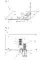
- FIG. 1 shows a device 1 for characterizing objects 2 in one Sample manipulation system 3, in which the objects 2 on at least one, im essential horizontal working field 4 with a longitudinal extent X and a Transverse extension Y are arranged.
- This device 1 comprises at least one parallel to the X-direction extending rail 5 and one by means of drives on this rail 5 in the X direction back and forth movable displacement unit.
- the displacement unit preferably comprises a tool 7 for characterization an object 2 and a motor-driven gripping mechanism 8 for Grasping and approaching an object 2 to the characterization tool 7.
- the device 1 comprises a processor (not shown) for controlling the movements the displacement unit 6 and the actions of the gripping mechanism 8 and for processing the information provided by the characterization tool 7.
- FIG. 2 shows a schematic plan view of a preferred, first embodiment a device according to the invention 1.
- This device comprises in addition to the elements of the working platform shown in Figure 1, a displacement unit 6 with one with this displacement along along the Rail 5 movable support device 9 for transporting objects 2 in X-direction.
- the support device 9 is formed here as a support plate 11, which together with the displacement unit 6, the tool 7 for characterization an object 2 and a motor-driven gripping mechanism 8 for Grasping and approaching an object 2 along the characterization tool 7 along the rail 5 is movable.
- the gripping mechanism 8 objects be it carriers (as shown in FIG. 2), microplates, tube holders, Troughs or other containers for samples or liquids, on the support plate 11 pulled and transported on this support device 9 in the X direction.
- the here used as a characterization tool 7 Barcode reader one side of the first microplate 2 and / or one side of the carrier 2 'and so scans the identity of the samples in the corresponding wells finds. This identification is preferably carried out during which the carrier 2 '. is pulled on the support plate 11 of the support device 9. According to the current X-position of this support plate 11 is the recorded object of its original Position on the work surface 4 can be assigned. This capture of the X position the support plate 11, the travel of the gripping mechanism 8 for grasping of the object (original Y-position of the object) takes place via suitable Sensors for detecting linear movements, such as those of the skilled person known in the art. Processing the information of this Sensors (not shown in Fig.
- the bar code reader used in FIG. 2 as a characterization tool 7 preferably travels along the rail 5 in a first passage and reads the identification marks or flags of the carriers, which preferentially all are essentially vertically readable from behind. On the basis of this data, it is recognized, for example, which types of carriers are involved and whether they can simply be dragged onto the platform surface during subsequent transport. Likewise, it is preferably apparent from these data whether and at which locations and angles the corresponding barcodes of the objects positioned on the carriers are to be expected.
- a double identification is thus preferably carried out first, and only later (if necessary) is a direct subsequent check performed.
- the gripping mechanism 8 is designed here as a telescopic arm; Alternatively it can also be designed as an articulated arm.
- Another (not shown) alternative Embodiment of the gripping mechanism comprises one in the Y direction extending rail with a crawler, which raised or lowered can be used to to capture or deposit the carriers.
- this Carrying device 9 an object 2, which the characterizing tool. 7 was approximated, transported in the X direction and on it by means of Gripping mechanism 8 are deposited at a position on the working field, the is different from the original position of the object on the desktop.
- objects 2 are using the gripping mechanism 8 not only detected, transported in a plane and again can be deposited; Rather, objects 2 can also be from one level transported in a Z-direction above or below arranged plane and be deposited there.
- the objects each with the characterization tool 7 identified or otherwise characterized it is advantageous but not necessarily require the objects each with the characterization tool 7 identified or otherwise characterized.
- Figure 3 shows a schematic plan view of a second embodiment of a Device 1 according to the invention for characterizing objects 2 in one Sample manipulation system 3, in which the objects 2 on at least one, substantially horizontal working field 4 with a longitudinal extent X and a Transverse extension Y are arranged.
- This device 1 comprises at least a parallel to the X-direction extending rail 5 and one by means of drives on this rail 5 in the X direction back and forth movable displacement unit 6, preferably with a tool 7 for characterizing an object 2 and a motor-driven gripping mechanism 8 for grasping and approaching of an object 2 to the characterization tool 7.
- the device 1 comprises a processor for controlling the movements of the displacement unit 6 and the actions of the gripping mechanism 8 and for processing of the Characterization tool 7 possibly supplied information.
- the inventive Device 1 is characterized in that the displacement unit 6 a with her along the rail 5 movable support device 9 for Transporting objects 2 in the X direction includes.
- the carrying device 9 comprises one for carrying the objects 2,2 'formed support plate 11 and a gripping mechanism 8 for Detecting objects 2 at a recording location, for conveying these objects 2 on the transport plate 11 and for depositing these objects 2 at a delivery location.
- the gripping mechanism 8 is extendable in the Y direction over at least the extent of an object 2, 2 'positioned on the working field 4 and designed as a telescopic arm or articulated arm.
- the rail 5 is preferably arranged outside the working field 4 and has a length which corresponds at least to the longitudinal extent X of the working field 4.
- the rail 5 can also be designed to be longer than the working field 4 of the sample manipulation system 3. This makes it possible for objects to be picked up from outside this sample manipulation system 3 and positioned on the working field 4.
- the storage of objects that are to be removed from the working field 4, outside of the sample manipulation system 3 is made possible.
- a device 1 in which the support device 9 with respect to a perpendicular to the horizontal working field 4 Z-axis 10 by an angle ⁇ , which is preferably + 180 ° and / or - 180 °, is rotatable.
- two sample manipulation systems 3, 3 ' which are arranged parallel to each other and at the same working height (see Fig. 3), can be operated with only one device.
- the characterization tool 7 may include a bar code reader and / or an IR thermometer and / or a spectroscope and / or a tube inspection unit and / or a camera.
- the invention also relates to sample manipulation systems 3 with at least one of the devices 1 described so far.
- Such systems can be designed as a single working platform 14 and a single working field 4 or two (or more) substantially horizontal working fields 4, 4 'each having a longitudinal extent X, X 'and each have a transverse extent Y, Y' include.
- these working fields 4,4 ' are preferably arranged in a plane and parallel to each other.
- the working fields 4,4 ' can also be parallel to each other or a practical any angle ⁇ twisted to be arranged one above the other (not shown).
- Another combination option (not shown) of two working fields 4,4 ' is that these in two parallel successively arranged working platforms 14,14 'are placed, leaving the back of the first platform facing the front of the second platform.
- An additional (not shown) combination option of two working fields 4,4 ' is that these are placed in parallel one behind the other so that the back of the first platform faces the front of the second platform.
- the inventive device 1 which in such cases preferably at the Rear side of the first platform is arranged, without turning on the front and / or rear work platform.
- the displacement unit 6 with the optional characterization tool 7 and the motor-driven gripping mechanism 8 is then at least one between the two working fields 4,4 'arranged, parallel to the X direction or X'-direction extending rail 5 by means of drives back and forth.
- the displacement unit 6 with the characterization tool 7 and the motor driven gripping mechanism 8 can also on two rails 5 (not shown) to be arranged to move back and forth.
- the invention also includes corresponding methods for transporting and preferably also for characterizing objects 2 in one or more Probenmanipuliersystemen 3, wherein objects 2 at a first X / Y position with detected the gripping mechanism 8, the characterizing tool 7 approximated, characterized by this characterization tool 7, in the X direction transported and deposited at a second X / Y position again.
- the objects 2 according to a first embodiment pulled on a plate 11 of a support device 9 and on this support plate 11 transported in the X direction.
- the objects 2 are lifted with a gripping mechanism 8 and with this gripping mechanism 8 transported in the X direction.
- characterization according to the invention and transport method applied to a system which two or more work fields 4,4 ', so objects 2,2' at a first X / Y position detected in a first working field 4 and at a second X / Y position in a second working field 4 ', which is preferably parallel to the first Work area 4 and above, below or next to this, deposited become. Also, objects 2,2 'outside the first or second field of work 4,4 'recorded and / or delivered.
- working fields 4,4 ' is the support device 9 - between detecting and depositing an object 2,2 '- with respect to a perpendicular to the horizontal working field 4 Z-axis 10 by an angle ⁇ , the preferably + 180 ° and / or - 180 °, rotated.
- It can be a single Microplate (as shown) or even an entire carrier with e.g. three microplates or racks of, for example, 16 sample tubes (both not shown) be transported from a first working field 4 to a second working field 4 '.
- a tube inspection unit is here a device for performing a automatic transmission measurement on samples (e.g., blood samples in tubes) designated. In this way, with the inventive device the Presence, position and quality of samples are determined. usual Barcode readers capture a 1-D barcode.
- the characterization tool 7 is about one or more axes turn / tilt, so that the sample container or objects 2,2 'from different Solid angles can be observed or detected. Representing the himself in tilting or rotating axes in virtually any spatial position is a horizontal Tilting axis 12 each drawn in Figures 2 to 4.
- FIGS. 1 to 4 each denote the same features, even if not all features are explicitly named for each figure.
- parts the device 1 and the Probenmanipuliersystems 3 the every professional Selects to complete, e.g. Pipette tips, tubings which connect the pipette tips to the pumps, drives for the robotic manipulators and the like, have been omitted in the figures so that these become clearer.
- Such parts are of course part of the inventive Devices 1 or Systems 3. Any combinations of disclosed features of the invention belong to its scope.
- a non-illustrated variant of a Probenmanipuliersystems 3 comprises preferably at least one working field 4, 4 'or a working platform 14, 14', which is designed as inaccessible to people, protected area 15 is designed.
- One such protected area 15 may be a per se known flow cabinet or a Include low pressure chamber and possibly present persons before one Protect contamination (bio hazard) by samples to be processed.
- a protected area 15 comprises a lock 16 over which Objects 2 or samples in e.g. the flow cabinet in or out of this can be transported.
- the inventive device 1 can to be designed for this purpose as part of this lock 16 and their transport function To run.
- the protected area 15 of a working field can therefore also from the rest be separated from a work platform or a system so that a person Do not touch or damage delicate parts.
- a person Do not touch or damage delicate parts For example could be an unintentional misalignment of a Multipipettenkopfes (with, for example, 1536 extremely precisely set pipetting needles) or just one slight displacement of a high-precision carrier fatal impact, so that the pipetting needles are damaged by touching the microplate surface could.
- Other misalignments could cause blocking or confusion contribute to samples.
Landscapes
- Analytical Chemistry (AREA)
- Immunology (AREA)
- Physics & Mathematics (AREA)
- Health & Medical Sciences (AREA)
- Life Sciences & Earth Sciences (AREA)
- Chemical & Material Sciences (AREA)
- Pathology (AREA)
- General Health & Medical Sciences (AREA)
- Biochemistry (AREA)
- General Physics & Mathematics (AREA)
- Engineering & Computer Science (AREA)
- Robotics (AREA)
- Automatic Analysis And Handling Materials Therefor (AREA)
- Sampling And Sample Adjustment (AREA)
- Apparatus Associated With Microorganisms And Enzymes (AREA)
Applications Claiming Priority (2)
| Application Number | Priority Date | Filing Date | Title |
|---|---|---|---|
| CH12172003 | 2003-07-11 | ||
| CH12172003 | 2003-07-11 |
Publications (3)
| Publication Number | Publication Date |
|---|---|
| EP1496365A2 true EP1496365A2 (fr) | 2005-01-12 |
| EP1496365A3 EP1496365A3 (fr) | 2012-02-01 |
| EP1496365B1 EP1496365B1 (fr) | 2014-06-04 |
Family
ID=33438120
Family Applications (1)
| Application Number | Title | Priority Date | Filing Date |
|---|---|---|---|
| EP04015100.3A Expired - Lifetime EP1496365B1 (fr) | 2003-07-11 | 2004-06-28 | Dispositif et procédé de transport d'objets |
Country Status (3)
| Country | Link |
|---|---|
| US (1) | US7264432B2 (fr) |
| EP (1) | EP1496365B1 (fr) |
| JP (1) | JP4430996B2 (fr) |
Cited By (8)
| Publication number | Priority date | Publication date | Assignee | Title |
|---|---|---|---|---|
| DE102006049208A1 (de) * | 2006-10-18 | 2008-04-24 | Polysius Ag | Laborsystem |
| US10296769B2 (en) | 2016-02-01 | 2019-05-21 | Roche Molecular Systems, Inc. | Method for teaching positioning of a bar code scanner and apparatus for processing a sample or reagent |
| CN112249579A (zh) * | 2020-10-23 | 2021-01-22 | 南京晓庄学院 | 差动集散控制式中药自动配发装置 |
| DE102024101358A1 (de) * | 2024-01-17 | 2025-07-17 | Hamilton Bonaduz Ag | Labormoduletagere aus übereinander angeordneten Labormodulen |
| DE102024116148A1 (de) * | 2024-06-10 | 2025-12-11 | Analytik Jena Gmbh+Co. Kg | Trägereinheit für den Transport eines Objekts |
| DE102024116178A1 (de) * | 2024-06-10 | 2025-12-11 | Analytik Jena Gmbh+Co. Kg | Lagermodul für ein Probengerät |
| DE102024116179A1 (de) * | 2024-06-10 | 2025-12-11 | Analytik Jena Gmbh+Co. Kg | Verfahren zur Beschickung eines Probengeräts |
| DE102024116144A1 (de) * | 2024-06-10 | 2025-12-11 | Analytik Jena Gmbh+Co. Kg | Vorrichtung zum Beistellen von Objekten für ein Probengerät sowie Anlage mit Probengerät |
Families Citing this family (18)
| Publication number | Priority date | Publication date | Assignee | Title |
|---|---|---|---|---|
| US7976260B2 (en) * | 2005-03-15 | 2011-07-12 | Hirata Corporation | Work handling apparatus |
| US20080003092A1 (en) * | 2006-06-30 | 2008-01-03 | Petar Baclija | Rotary union connection |
| JP4875951B2 (ja) * | 2006-08-31 | 2012-02-15 | Juki株式会社 | 自動分注装置、及び、その検体供給用架設台 |
| EP2188638A1 (fr) * | 2007-08-15 | 2010-05-26 | Christophe Alain Guex | Appareil et procédé de transport de récipients |
| ES2402225T3 (es) * | 2008-07-25 | 2013-04-29 | F. Hoffmann-La Roche Ag | Un método y un sistema de laboratorio para la manipulación de tubos de muestras y una unidad de análisis por imagen |
| EP2148204B1 (fr) * | 2008-07-25 | 2013-01-02 | F. Hoffmann-La Roche AG | Système de stockage et d'extraction de laboratoire et procédé pour manipuler des tubes d'échantillons |
| EP2148206B1 (fr) * | 2008-07-25 | 2015-11-18 | F.Hoffmann-La Roche Ag | Système de laboratoire pour la manipulation de portoir de tubes d'échantillons, et élément d'alignement pour portoirs de tubes d'échantillons et ensemble recevant le plateau de portoirs |
| ES2582205T3 (es) | 2008-07-25 | 2016-09-09 | F. Hoffmann-La Roche Ag | Método y sistema de laboratorio para manipular gradillas de tubos de muestra |
| CA3009281C (fr) | 2011-09-09 | 2021-10-19 | Gen-Probe Incorporated | Instrumentation de maniement automatise d'echantillons, systemes, processus et procedes associes |
| KR20140092378A (ko) * | 2011-11-07 | 2014-07-23 | 베크만 컬터, 인코포레이티드 | 샘플을 처리하기 위한 시스템 및 방법 |
| US10668622B2 (en) | 2012-10-11 | 2020-06-02 | Siemens Healthcare Diagnostics Inc. | Automation maintenance carrier |
| DE102012020679B4 (de) * | 2012-10-22 | 2022-01-05 | Grenzebach Maschinenbau Gmbh | Verfahren und Vorrichtung zum schnellen Versetzen von Platten |
| AU2013202805B2 (en) * | 2013-03-14 | 2015-07-16 | Gen-Probe Incorporated | System and method for extending the capabilities of a diagnostic analyzer |
| CN103884856B (zh) * | 2014-04-01 | 2015-06-10 | 重庆科斯迈生物科技有限公司 | 化学发光免疫分析仪杯条运送系统 |
| CN107271705B (zh) * | 2017-06-30 | 2018-10-16 | 江南大学 | 一种生产流水线式的高通量筛选系统 |
| CN108482925B (zh) * | 2018-02-28 | 2019-02-22 | 中国烟草总公司北京市公司物流中心 | 一种暂存区管理方法 |
| CN110018320A (zh) * | 2019-03-29 | 2019-07-16 | 赫安仕科技(苏州)有限公司 | 一种检测驱动装置及驱动方法 |
| JPWO2024142561A1 (fr) | 2022-12-28 | 2024-07-04 |
Citations (5)
| Publication number | Priority date | Publication date | Assignee | Title |
|---|---|---|---|---|
| EP0317325A2 (fr) | 1987-11-20 | 1989-05-24 | Hewlett-Packard Company | Dispositif d'identification d'échantillons judiciaires et station d'impression pour ledit dispositif |
| WO1992022880A1 (fr) | 1991-06-13 | 1992-12-23 | Abbott Laboratories | Procede de visualisation destine a la detection d'agglutination |
| US5388946A (en) | 1988-01-20 | 1995-02-14 | Grau Gmbh & Co. | Systems and methods for the automated archiving and retrieval of computer data storage cassettes |
| US6060022A (en) | 1996-07-05 | 2000-05-09 | Beckman Coulter, Inc. | Automated sample processing system including automatic centrifuge device |
| WO2001057538A1 (fr) | 2000-02-01 | 2001-08-09 | Incyte Genomics, Inc. | Procede et appareil pour convoyer par navette des plaques de microtitration |
Family Cites Families (5)
| Publication number | Priority date | Publication date | Assignee | Title |
|---|---|---|---|---|
| US5125150A (en) * | 1991-09-03 | 1992-06-30 | Amp Incorporated | Tool for mass terminating wires to electrical connectors |
| EP0629858A1 (fr) * | 1993-06-16 | 1994-12-21 | Kabushiki Kaisha Nittec | Appareil pour préparer des échantillons |
| JP2002060011A (ja) * | 2000-08-11 | 2002-02-26 | Murata Mach Ltd | 自動倉庫 |
| DE60139922D1 (de) * | 2001-04-05 | 2009-10-29 | Inpeco Ip Ltd | Verfahren zur Verwaltung von Arbeitszellensystemen mit einem Automatisierungsverwaltungssystem |
| US6923612B2 (en) * | 2002-03-29 | 2005-08-02 | TGW Transportgeräte GmbH & Co. KG | Load-handling system and telescopic arm therefor |
-
2004
- 2004-06-28 EP EP04015100.3A patent/EP1496365B1/fr not_active Expired - Lifetime
- 2004-07-08 US US10/886,887 patent/US7264432B2/en not_active Expired - Lifetime
- 2004-07-09 JP JP2004203123A patent/JP4430996B2/ja not_active Expired - Lifetime
Patent Citations (5)
| Publication number | Priority date | Publication date | Assignee | Title |
|---|---|---|---|---|
| EP0317325A2 (fr) | 1987-11-20 | 1989-05-24 | Hewlett-Packard Company | Dispositif d'identification d'échantillons judiciaires et station d'impression pour ledit dispositif |
| US5388946A (en) | 1988-01-20 | 1995-02-14 | Grau Gmbh & Co. | Systems and methods for the automated archiving and retrieval of computer data storage cassettes |
| WO1992022880A1 (fr) | 1991-06-13 | 1992-12-23 | Abbott Laboratories | Procede de visualisation destine a la detection d'agglutination |
| US6060022A (en) | 1996-07-05 | 2000-05-09 | Beckman Coulter, Inc. | Automated sample processing system including automatic centrifuge device |
| WO2001057538A1 (fr) | 2000-02-01 | 2001-08-09 | Incyte Genomics, Inc. | Procede et appareil pour convoyer par navette des plaques de microtitration |
Cited By (8)
| Publication number | Priority date | Publication date | Assignee | Title |
|---|---|---|---|---|
| DE102006049208A1 (de) * | 2006-10-18 | 2008-04-24 | Polysius Ag | Laborsystem |
| US10296769B2 (en) | 2016-02-01 | 2019-05-21 | Roche Molecular Systems, Inc. | Method for teaching positioning of a bar code scanner and apparatus for processing a sample or reagent |
| CN112249579A (zh) * | 2020-10-23 | 2021-01-22 | 南京晓庄学院 | 差动集散控制式中药自动配发装置 |
| DE102024101358A1 (de) * | 2024-01-17 | 2025-07-17 | Hamilton Bonaduz Ag | Labormoduletagere aus übereinander angeordneten Labormodulen |
| DE102024116148A1 (de) * | 2024-06-10 | 2025-12-11 | Analytik Jena Gmbh+Co. Kg | Trägereinheit für den Transport eines Objekts |
| DE102024116178A1 (de) * | 2024-06-10 | 2025-12-11 | Analytik Jena Gmbh+Co. Kg | Lagermodul für ein Probengerät |
| DE102024116179A1 (de) * | 2024-06-10 | 2025-12-11 | Analytik Jena Gmbh+Co. Kg | Verfahren zur Beschickung eines Probengeräts |
| DE102024116144A1 (de) * | 2024-06-10 | 2025-12-11 | Analytik Jena Gmbh+Co. Kg | Vorrichtung zum Beistellen von Objekten für ein Probengerät sowie Anlage mit Probengerät |
Also Published As
| Publication number | Publication date |
|---|---|
| JP4430996B2 (ja) | 2010-03-10 |
| US20050053454A1 (en) | 2005-03-10 |
| US7264432B2 (en) | 2007-09-04 |
| EP1496365A3 (fr) | 2012-02-01 |
| JP2005031087A (ja) | 2005-02-03 |
| EP1496365B1 (fr) | 2014-06-04 |
Similar Documents
| Publication | Publication Date | Title |
|---|---|---|
| EP1496365B1 (fr) | Dispositif et procédé de transport d'objets | |
| EP1759215B1 (fr) | Dispositif et procede pour disposer des pointes de pipette ou de distributeur dans un systeme servant a manipuler des echantillons liquides | |
| DE102008022835B3 (de) | Analysegerät | |
| DE3872341T2 (de) | Geraet zum durchfuehren einer fluessigkeitsreaktion. | |
| DE69429840T2 (de) | Transportsystem für ein Analysengerät für Flüssigkeiten | |
| DE112010000822B4 (de) | Automatische Analysevorrichtung und automatisches Analyseverfahren | |
| DE60000539T2 (de) | Vorrichtung und verfahren zur übertragung von kleinen substanzvolumen | |
| DE69835795T2 (de) | Vorrichtung zur automatischen Durchführung von Laboratoriumprüfungen | |
| DE602004013176T2 (de) | Vorrichtung zur durchführung von analysen in biologischen flüssigkeiten und damit verbundenes verfahren | |
| EP2027926B1 (fr) | Appareil de fonctionnement de matériel biologique | |
| CH706811A1 (de) | Mikroplatten-Reader mit Deckelabheber für Mikroplatten. | |
| EP3759502B1 (fr) | Appareil de mesure pour un appareil automatique de laboratoire de mesure d'un objet, objet pour ledit appareil de mesure et procédé de mesure | |
| EP2730927A1 (fr) | Poste de réactif pour un appareil d'analyse automatique | |
| EP2998744B1 (fr) | Dispositif d'incubation pour un appareil d'analyse automatique | |
| WO2012146770A1 (fr) | Dispositif de poinçonnage pourvu d'une unité de préhension | |
| EP3666381A1 (fr) | Appareil automatique de laboratoire destiné au traitement automatique des échantillons de laboratoire | |
| WO2017001676A1 (fr) | Système de pipetage muni d'un dispositif de traitement d'images | |
| EP2420847B1 (fr) | Système de préparation d'échantillons et procédé de traitement d'un échantillon | |
| DE202015104718U1 (de) | Bauteilehandhabungsvorrichtung und System | |
| DE202008006338U1 (de) | Analysegerät | |
| DE102020134318A1 (de) | Handhabung von Laborelementen | |
| WO2013064237A2 (fr) | Détermination automatique de structures | |
| DE102011117273A1 (de) | Automatische Strukturbestimmung | |
| EP3173794B1 (fr) | Procede de transfert d'un volume de liquide dans un appareil d'analyse | |
| DE102020117973A1 (de) | Roboterzelle zur Handhabung von Stückgut |
Legal Events
| Date | Code | Title | Description |
|---|---|---|---|
| PUAI | Public reference made under article 153(3) epc to a published international application that has entered the european phase |
Free format text: ORIGINAL CODE: 0009012 |
|
| AK | Designated contracting states |
Kind code of ref document: A2 Designated state(s): AT BE BG CH CY CZ DE DK EE ES FI FR GB GR HU IE IT LI LU MC NL PL PT RO SE SI SK TR |
|
| AX | Request for extension of the european patent |
Extension state: AL HR LT LV MK |
|
| PUAL | Search report despatched |
Free format text: ORIGINAL CODE: 0009013 |
|
| RIC1 | Information provided on ipc code assigned before grant |
Ipc: B65G 1/04 20060101ALI20111219BHEP Ipc: G01N 35/00 20060101AFI20111219BHEP Ipc: G01N 35/02 20060101ALI20111219BHEP Ipc: G01N 35/04 20060101ALI20111219BHEP |
|
| AK | Designated contracting states |
Kind code of ref document: A3 Designated state(s): AT BE BG CH CY CZ DE DK EE ES FI FR GB GR HU IE IT LI LU MC NL PL PT RO SE SI SK TR |
|
| AX | Request for extension of the european patent |
Extension state: AL HR LT LV MK |
|
| RIC1 | Information provided on ipc code assigned before grant |
Ipc: G01N 35/02 20060101ALI20111223BHEP Ipc: G01N 35/00 20060101AFI20111223BHEP Ipc: B65G 1/04 20060101ALI20111223BHEP Ipc: G01N 35/04 20060101ALI20111223BHEP |
|
| 17P | Request for examination filed |
Effective date: 20120614 |
|
| AKX | Designation fees paid |
Designated state(s): CH DE FR GB LI |
|
| 17Q | First examination report despatched |
Effective date: 20120921 |
|
| GRAP | Despatch of communication of intention to grant a patent |
Free format text: ORIGINAL CODE: EPIDOSNIGR1 |
|
| INTG | Intention to grant announced |
Effective date: 20140102 |
|
| GRAS | Grant fee paid |
Free format text: ORIGINAL CODE: EPIDOSNIGR3 |
|
| GRAA | (expected) grant |
Free format text: ORIGINAL CODE: 0009210 |
|
| RIN1 | Information on inventor provided before grant (corrected) |
Inventor name: OBERHOLZER, ALOIS Inventor name: MUERSET, PETER Inventor name: SCHINZEL, FRED Inventor name: ROMER, HANSPETER Inventor name: BATLINER, GREGOR Inventor name: WIGGLI, MARKUS |
|
| AK | Designated contracting states |
Kind code of ref document: B1 Designated state(s): CH DE FR GB LI |
|
| REG | Reference to a national code |
Ref country code: GB Ref legal event code: FG4D Free format text: NOT ENGLISH |
|
| RIN2 | Information on inventor provided after grant (corrected) |
Inventor name: ROMER, HANSPETER Inventor name: OBERHOLZER, ALOIS Inventor name: SCHINZEL, FRED Inventor name: MUERSET, PETER Inventor name: WIGGLI, MARKUS Inventor name: BATLINER, GREGOR |
|
| REG | Reference to a national code |
Ref country code: CH Ref legal event code: EP |
|
| REG | Reference to a national code |
Ref country code: DE Ref legal event code: R096 Ref document number: 502004014627 Country of ref document: DE Effective date: 20140710 |
|
| REG | Reference to a national code |
Ref country code: CH Ref legal event code: NV Representative=s name: OK PAT AG PATENTE MARKEN LIZENZEN, CH |
|
| REG | Reference to a national code |
Ref country code: DE Ref legal event code: R097 Ref document number: 502004014627 Country of ref document: DE |
|
| PLBE | No opposition filed within time limit |
Free format text: ORIGINAL CODE: 0009261 |
|
| STAA | Information on the status of an ep patent application or granted ep patent |
Free format text: STATUS: NO OPPOSITION FILED WITHIN TIME LIMIT |
|
| 26N | No opposition filed |
Effective date: 20150305 |
|
| REG | Reference to a national code |
Ref country code: DE Ref legal event code: R097 Ref document number: 502004014627 Country of ref document: DE Effective date: 20150305 |
|
| REG | Reference to a national code |
Ref country code: FR Ref legal event code: PLFP Year of fee payment: 13 |
|
| REG | Reference to a national code |
Ref country code: FR Ref legal event code: PLFP Year of fee payment: 14 |
|
| REG | Reference to a national code |
Ref country code: FR Ref legal event code: PLFP Year of fee payment: 15 |
|
| REG | Reference to a national code |
Ref country code: CH Ref legal event code: PFUS Owner name: TECAN TRADING AG, CH Free format text: FORMER OWNER: TECAN TRADING AG, CH |
|
| PGFP | Annual fee paid to national office [announced via postgrant information from national office to epo] |
Ref country code: FR Payment date: 20230510 Year of fee payment: 20 Ref country code: DE Payment date: 20230502 Year of fee payment: 20 |
|
| PGFP | Annual fee paid to national office [announced via postgrant information from national office to epo] |
Ref country code: GB Payment date: 20230504 Year of fee payment: 20 Ref country code: CH Payment date: 20230702 Year of fee payment: 20 |
|
| REG | Reference to a national code |
Ref country code: CH Ref legal event code: PL |
|
| PG25 | Lapsed in a contracting state [announced via postgrant information from national office to epo] |
Ref country code: GB Free format text: LAPSE BECAUSE OF EXPIRATION OF PROTECTION Effective date: 20240627 |
|
| REG | Reference to a national code |
Ref country code: GB Ref legal event code: PE20 Expiry date: 20240627 |
|
| PG25 | Lapsed in a contracting state [announced via postgrant information from national office to epo] |
Ref country code: GB Free format text: LAPSE BECAUSE OF EXPIRATION OF PROTECTION Effective date: 20240627 |