EP1496495B1 - Pixelschaltung für eine organische lichtemittierende Vorrichtung mit Selbstkompensation der Schwellenspannung und Ansteuerungsverfahren dafür - Google Patents
Pixelschaltung für eine organische lichtemittierende Vorrichtung mit Selbstkompensation der Schwellenspannung und Ansteuerungsverfahren dafür Download PDFInfo
- Publication number
- EP1496495B1 EP1496495B1 EP04090270.2A EP04090270A EP1496495B1 EP 1496495 B1 EP1496495 B1 EP 1496495B1 EP 04090270 A EP04090270 A EP 04090270A EP 1496495 B1 EP1496495 B1 EP 1496495B1
- Authority
- EP
- European Patent Office
- Prior art keywords
- transistor
- current
- gate
- signal
- light emitting
- Prior art date
- Legal status (The legal status is an assumption and is not a legal conclusion. Google has not performed a legal analysis and makes no representation as to the accuracy of the status listed.)
- Expired - Lifetime
Links
- 238000000034 method Methods 0.000 title claims description 12
- 239000003990 capacitor Substances 0.000 claims description 27
- 239000010409 thin film Substances 0.000 description 10
- 229920001621 AMOLED Polymers 0.000 description 5
- 238000004519 manufacturing process Methods 0.000 description 5
- 238000010276 construction Methods 0.000 description 4
- 238000010586 diagram Methods 0.000 description 4
- 230000008901 benefit Effects 0.000 description 3
- 239000011159 matrix material Substances 0.000 description 2
- 230000015556 catabolic process Effects 0.000 description 1
- 238000006731 degradation reaction Methods 0.000 description 1
- 238000007599 discharging Methods 0.000 description 1
- 230000003071 parasitic effect Effects 0.000 description 1
- 239000000758 substrate Substances 0.000 description 1
Images


Classifications
-
- G—PHYSICS
- G09—EDUCATION; CRYPTOGRAPHY; DISPLAY; ADVERTISING; SEALS
- G09G—ARRANGEMENTS OR CIRCUITS FOR CONTROL OF INDICATING DEVICES USING STATIC MEANS TO PRESENT VARIABLE INFORMATION
- G09G3/00—Control arrangements or circuits, of interest only in connection with visual indicators other than cathode-ray tubes
- G09G3/20—Control arrangements or circuits, of interest only in connection with visual indicators other than cathode-ray tubes for presentation of an assembly of a number of characters, e.g. a page, by composing the assembly by combination of individual elements arranged in a matrix no fixed position being assigned to or needed to be assigned to the individual characters or partial characters
- G09G3/22—Control arrangements or circuits, of interest only in connection with visual indicators other than cathode-ray tubes for presentation of an assembly of a number of characters, e.g. a page, by composing the assembly by combination of individual elements arranged in a matrix no fixed position being assigned to or needed to be assigned to the individual characters or partial characters using controlled light sources
- G09G3/30—Control arrangements or circuits, of interest only in connection with visual indicators other than cathode-ray tubes for presentation of an assembly of a number of characters, e.g. a page, by composing the assembly by combination of individual elements arranged in a matrix no fixed position being assigned to or needed to be assigned to the individual characters or partial characters using controlled light sources using electroluminescent panels
- G09G3/32—Control arrangements or circuits, of interest only in connection with visual indicators other than cathode-ray tubes for presentation of an assembly of a number of characters, e.g. a page, by composing the assembly by combination of individual elements arranged in a matrix no fixed position being assigned to or needed to be assigned to the individual characters or partial characters using controlled light sources using electroluminescent panels semiconductive, e.g. using light-emitting diodes [LED]
- G09G3/3208—Control arrangements or circuits, of interest only in connection with visual indicators other than cathode-ray tubes for presentation of an assembly of a number of characters, e.g. a page, by composing the assembly by combination of individual elements arranged in a matrix no fixed position being assigned to or needed to be assigned to the individual characters or partial characters using controlled light sources using electroluminescent panels semiconductive, e.g. using light-emitting diodes [LED] organic, e.g. using organic light-emitting diodes [OLED]
- G09G3/3225—Control arrangements or circuits, of interest only in connection with visual indicators other than cathode-ray tubes for presentation of an assembly of a number of characters, e.g. a page, by composing the assembly by combination of individual elements arranged in a matrix no fixed position being assigned to or needed to be assigned to the individual characters or partial characters using controlled light sources using electroluminescent panels semiconductive, e.g. using light-emitting diodes [LED] organic, e.g. using organic light-emitting diodes [OLED] using an active matrix
- G09G3/3233—Control arrangements or circuits, of interest only in connection with visual indicators other than cathode-ray tubes for presentation of an assembly of a number of characters, e.g. a page, by composing the assembly by combination of individual elements arranged in a matrix no fixed position being assigned to or needed to be assigned to the individual characters or partial characters using controlled light sources using electroluminescent panels semiconductive, e.g. using light-emitting diodes [LED] organic, e.g. using organic light-emitting diodes [OLED] using an active matrix with pixel circuitry controlling the current through the light-emitting element
-
- G—PHYSICS
- G09—EDUCATION; CRYPTOGRAPHY; DISPLAY; ADVERTISING; SEALS
- G09G—ARRANGEMENTS OR CIRCUITS FOR CONTROL OF INDICATING DEVICES USING STATIC MEANS TO PRESENT VARIABLE INFORMATION
- G09G2300/00—Aspects of the constitution of display devices
- G09G2300/08—Active matrix structure, i.e. with use of active elements, inclusive of non-linear two terminal elements, in the pixels together with light emitting or modulating elements
- G09G2300/0809—Several active elements per pixel in active matrix panels
- G09G2300/0819—Several active elements per pixel in active matrix panels used for counteracting undesired variations, e.g. feedback or autozeroing
-
- G—PHYSICS
- G09—EDUCATION; CRYPTOGRAPHY; DISPLAY; ADVERTISING; SEALS
- G09G—ARRANGEMENTS OR CIRCUITS FOR CONTROL OF INDICATING DEVICES USING STATIC MEANS TO PRESENT VARIABLE INFORMATION
- G09G2300/00—Aspects of the constitution of display devices
- G09G2300/08—Active matrix structure, i.e. with use of active elements, inclusive of non-linear two terminal elements, in the pixels together with light emitting or modulating elements
- G09G2300/0809—Several active elements per pixel in active matrix panels
- G09G2300/0842—Several active elements per pixel in active matrix panels forming a memory circuit, e.g. a dynamic memory with one capacitor
- G09G2300/0861—Several active elements per pixel in active matrix panels forming a memory circuit, e.g. a dynamic memory with one capacitor with additional control of the display period without amending the charge stored in a pixel memory, e.g. by means of additional select electrodes
-
- G—PHYSICS
- G09—EDUCATION; CRYPTOGRAPHY; DISPLAY; ADVERTISING; SEALS
- G09G—ARRANGEMENTS OR CIRCUITS FOR CONTROL OF INDICATING DEVICES USING STATIC MEANS TO PRESENT VARIABLE INFORMATION
- G09G2310/00—Command of the display device
- G09G2310/02—Addressing, scanning or driving the display screen or processing steps related thereto
- G09G2310/0243—Details of the generation of driving signals
- G09G2310/0251—Precharge or discharge of pixel before applying new pixel voltage
-
- G—PHYSICS
- G09—EDUCATION; CRYPTOGRAPHY; DISPLAY; ADVERTISING; SEALS
- G09G—ARRANGEMENTS OR CIRCUITS FOR CONTROL OF INDICATING DEVICES USING STATIC MEANS TO PRESENT VARIABLE INFORMATION
- G09G2310/00—Command of the display device
- G09G2310/02—Addressing, scanning or driving the display screen or processing steps related thereto
- G09G2310/0262—The addressing of the pixel, in a display other than an active matrix LCD, involving the control of two or more scan electrodes or two or more data electrodes, e.g. pixel voltage dependent on signals of two data electrodes
-
- G—PHYSICS
- G09—EDUCATION; CRYPTOGRAPHY; DISPLAY; ADVERTISING; SEALS
- G09G—ARRANGEMENTS OR CIRCUITS FOR CONTROL OF INDICATING DEVICES USING STATIC MEANS TO PRESENT VARIABLE INFORMATION
- G09G2320/00—Control of display operating conditions
- G09G2320/04—Maintaining the quality of display appearance
- G09G2320/043—Preventing or counteracting the effects of ageing
- G09G2320/045—Compensation of drifts in the characteristics of light emitting or modulating elements
Definitions
- the present invention relates to a flat panel display and, more specifically, to a pixel circuit in an organic light emitting device capable of realizing high gradation by self-compensating a threshold voltage of a transistor that drives an electroluminescent (EL) element, and a method for driving the same.
- EL electroluminescent
- an organic light emitting device may be classified into a passive matrix organic light emitting diode (OLED) and an active matrix OLED (AMOLED), and can be classified into a current driving OLED and a voltage driving OLED depending on the manner in which the EL element is driven.
- OLED passive matrix organic light emitting diode
- AMOLED active matrix OLED
- a typical AMOLED is generally composed of a plurality of gate lines, a plurality of data lines, a plurality of power lines, and a plurality of pixels connected to the lines and arranged in a matrix form.
- Each pixel is normally composed of: an EL element; two transistors, in which one is a switching transistor for transferring a data signal while the other is a driving transistor for driving the EL element depending on the data signal; and one capacitor for maintaining the data voltage.
- this AMOLED has an advantage in that power consumption is low, current intensity flowing through the EL element changing over time, causing display nonuniformity, can be a problem. This results from a change in voltage between the gate and the source of the driving transistor for driving the EL element, namely, the threshold voltage of the driving transistor, which leads to a change in the current flowing through the EL element. Since the threshold voltage of a thin film transistor for the driving transistor changes depending on manufacturing process parameters, it becomes difficult to manufacture transistors in the AMOLED so that all of the transistors have the same threshold voltage. Thus, there are threshold voltage deviations between pixels.
- U.S. Patent No. 6,229,506 discloses an organic light emitting device for compensating the threshold voltage deviation.
- the '506 patent discloses a pixel structure in which a current source adjusts a voltage between the source and the gate of a driving transistor with respect to an overdrive voltage thereof and compensates the threshold voltage deviation of the driving transistor.
- the organic light emitting device in the '506 patent performs a two-step operation involving a data load (data write) step and a continuous light-emitting step, in which a current source adjusts a voltage between the source and the gate of the driving transistor with respect to the overdrive voltage and compensates the threshold voltage deviation of the driving transistor.
- the organic light emitting device as described above employs a current driving approach for driving the EL element which depends on a data signal current level applied from the current source and has difficulty in charging a data line. Because a parasitic capacitance of the data line is relatively large while the current level of the data signal provided from the current source is relatively small, the data becomes unstable as well as considerably long time x is required to charge the data line.
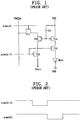
- Fig. 1 shows a pixel circuit of a voltage driving manner having a mirror type in a conventional voltage driving organic light emitting device.
- the pixel circuit comprises first P-type transistor T11 in which the gate of the first transistor is connected to current scan signal SCAN[n] applied to an associated scan line of a plurality of gate lines. Data signal VDATAm applied to an associated data line of a plurality of data lines is applied to its source. Second P-type transistor T12 in which a previous scan signal SCAN[n-1] is applied to a scan line just before the current scan line is applied to its gate. hitialization voltage Vinti is applied to its drain. Third and fourth P-type transistors T13 and T14 have a mirror type configuration. Fifth N-type transistor T15 in which previous scan signal SCAN[n-1] is applied to its gate has its drain coupled to the drain of fourth transistor T14. EL element EL11 is connected between fifth transistor T15 and ground voltage VSS. First capacitor C11 is connected between the gate and the source of fourth transistor T14.
- a scan line to be currently driven is the n-th scan line.
- a scan signal applied to the n-th scan line is SCAN[n].
- a scan line driven before the current scan line is the (n-1)th scan line.
- a scan signal applied to the (n-1)th scan line is SCAN[n-1].
- transistor T12 is turned on and transistors T11 and T15 are turned off, such that mirror-type transistors T13 and T14 are also turned off. Accordingly, the data stored in capacitor C11 is initialized through transistor T12 to initialization voltage Vinti.
- transistor T12 is turned off and transistor T11 is turned on, such that mirror-type transistors T13 and T14 are turned on.
- a data signal voltage level VDATAm applied to the data line is transferred through transistor T13 to the gate of driving transistor T14.
- transistor T15 is turned on by previous scan signal SCAN[n-1]
- a driving current corresponding to the data signal voltage VDATAm applied to the gate of driving transistor T14 flows into EL element EL 11 for its light-emitting.
- I EL 11 represents the current flowing through organic EL element EL 11
- V GS(T14) represents a voltage between the source and the gate of transistor T14
- V TH(13) represents a threshold voltage of transistor T13
- V DATA represents a data voltage
- ß represents a constant value, respectively.
- a compensating thin film transistor having a diode form is connected to a gate of the driving transistor in order to compensate the threshold voltage of the driving transistor.
- threshold voltages of the thin film transistor for compensation and the thin film transistor for driving EL element drive are different from each other, threshold voltage deviation of the driving transistor is not compensated, as well.
- the present invention therefore, addresses the aforementioned problem of the prior art, and provides a pixel circuit in an organic light emitting device capable of detecting and self-compensating threshold voltage deviations, and a method for driving the same, as recited in the appended claims.
- a pixel circuit in an organic light emitting device capable of compensating threshold voltage deviations regardless of manufacturing process parameters, and a method for driving the same.
- a pixel circuit in an organic light emitting device is provided which is capable of allowing a driving current flowing through an EL element to be uniform regardless of threshold voltage deviation between respective pixels, and a method for driving the same.
- a pixel circuit in an organic light emitting device capable of realizing high gradation representation regardless of threshold voltage deviation between respective pixels, and a method for driving the same.
- a pixel circuit in an organic light emitting device A first transistor delivers a data signal voltage in response to a current scan line signal. A second transistor generates a driving current depending an the data signal voltage delivered through the first transistor. A third transistor detects and self-compensates threshold voltage deviations in the second transistor. A capacitor for stores the data signal voltage delivered to the second transistor. An electroluminescent element emits light corresponding to the driving current generated through the 15 second transistor.
- a fourth transistor delivers a power supply voltage to the second transistor when the light is emitted.
- a fifth transistor delivers the driving current, provided from the second transistor, depending an the data signal voltage when the light is emitted.
- An electroluminescent element emits light corresponding to the driving current delivered through the fifth transistor.
- the third transistor connects the second transistor in the form of a diode in response to the current scan signal, so that the second transistor detects and compensates its threshold voltage deviation in itself.
- An initialization transistor composed of a PMOS transistor includes a gate to which a previous scan live signal is applied, a source coupled to a gate of the first transistor and one terminal of the capacitor and a a drain coupled to an initialization voltage supply for discharging the capacitor in response to the previous scan signal. It is the fourth transistor which characterizes the invention.
- the first transistor is composed of a PMOS transistor including a gate to which the current scan line signal is applied, a source to which the data signal voltage is applied, and a drain coupled to the second transistor.
- the second transistor is composed of a PMOS transistor including a gate coupled to one terminal of the capacitor, a source coupled to the first transistor, and a drain coupled to the electroluminescent element.
- the third transistor is composed of a PMOS transistor including a gate to which the current scan signal is applied, and a drain and a source which are coupled to the gate and the drain of the second transistor, respectively, so that the second transistor is connected in the form of a diode in response to the current scan signal to self-compensate a threshold voltage of the second transistor.
- the fourth transistor is composed of a PMOS transistor including a gate to which the current light-emitting signal is applied, a source to which a power supply voltage is applied, and a drain coupled to the second transistor.
- the fifth transistor is composed of a PMOS transistor including a gate to which the current light-emitting signal is applied, a source coupled to the second transistor, and a drain coupled to the electroluminescent element.
- An electroluminescent element emits light depending on an applied driving current.
- a first transistor delivers a data signal voltage in response to a current scan line signal.
- a second transistor for generates a driving current to drive the electroluminescent element in response to the data signal voltage.
- a third transistor connects the second transistor in the form of a diode in response to a current scan signal to self-compensate a threshold voltage of the second transistor.
- a capacitor stores the data signal voltage delivered to the second transistor.
- a fourth transistor delivers a power supply voltage to the second transistor in response to a current light-emitting signal.
- a fifth transistor provides the driving current, provided from the second transistor, for the electroluminescent element in response to the current light-emitting signal.
- a first transistor includes a gate to which a current scan signal is applied, and a source to which a data signal voltage is applied.
- a second transistor has its source coupled to a drain of the first transistor.
- a third transistor has its drain and source connected between a gate and a drain of the second transistor.
- a fourth transistor includes a gate to which a current light-emitting signal is applied, a source to which a power supply voltage is applied, and a drain coupled to the source of the second transistor.
- a fifth transistor includes a gate to which the current light-emitting signal is applied, a source coupled to the drain of the second transistor, and a drain coupled to one terminal of an electroluminescent element.
- the electroluminescent element has one terminal coupled to the drain of the fifth transistor and the other terminal grounded.
- a capacitor has one terminal coupled to the gate of the second transistor. A power supply voltage is applied to the other terminal of the capacitor.
- a pixel circuit in an organic light emitting device having a plurality of data lines, a plurality of scan lines, a plurality of power lines, and a plurality of pixels each connected to one associated data line, scan line and power line of the plurality of data lines, scan lines and power lines.
- Each pixel comprises: a first transistor including a gate to which a current scan signal to be applied to the associated scan line is applied, and a source to which a data signal voltage from the data line is applied; a second transistor whose source is coupled to a drain of the first transistor; a third transistor whose drain and source are connected between a gate and a drain of the second transistor, respectively; a fourth emitting transistor including a gate to which a current light-emitting signal is applied, a source to which a power supply voltage from the power line is applied, and a drain coupled to the source of the second transistor; a fifth transistor including a gate to which the current light-emitting signal is applied, and a source coupled to the drain of the second transistor; an electroluminescent element including one terminal coupled to the drain of the fifth transistor and the other terminal grounded; and a capacitor including one terminal coupled to the gate of the second transistor, and the other terminal to which the power supply voltage from the power line is applied.
- a method of driving a pixel in an organic light emitting device having a plurality of data lines, a plurality of scan lines, a plurality of power lines, and a plurality of pixels each connected to an associated one data line, scan line and power line of the plurality of data lines, scan lines and power lines.
- the method comprises: performing initialization in response to a scan signal applied to a scan line just before the associated scan line; compensating threshold voltage deviation in response to a scan signal applied to the associated scan line, and programming a data voltage applied from the associated data line, regardless of the threshold voltage deviation; and generating a driving current corresponding to the data voltage to emit an electroluminescent (EL) element in response to a current light-emitting signal.
- EL electroluminescent
- the organic light emitting device in accordance with the present invention includes a plurality of gate lines; a plurality of data lines; a plurality of power lines; and a plurality of pixels each arranged in an associated gate line, data line and power line of the plurality of gate lines, data lines and power lines.
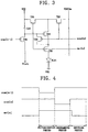
- Fig. 3 shows only one pixel arranged in an associated gate line (the n-th gate line), data line (the m-th data line) and power line (the m-th power line).
- each pixel in the organic light emitting device is composed of six transistors T31-T36, one capacitor C31 and electroluminescent (EL) element EL31. That is, each pixel includes organic electroluminescent device EL31 for emitting light corresponding to an applied driving current; first switching transistor T32 for switching data signal voltage VDATAm, applied to the associated data line, in response to current scan line signal SCAN[n] applied to the associated scan line; driving transistor T31 for supplying a driving current of the organic electroluminescent device corresponding to the data signal voltage inputted to its gate through first switching transistor T32; threshold voltage compensation transistor T33 for compensating the threshold voltage of driving transistor T31; and capacitor C31 for storing the data signal that is applied to the gate of driving transistor T31.
- first switching transistor T32 for switching data signal voltage VDATAm, applied to the associated data line, in response to current scan line signal SCAN[n] applied to the associated scan line
- driving transistor T31 for supplying a driving current of the organic electroluminescent device corresponding to the data signal voltage
- First switching transistor T32 is composed of a P-type thin film transistor in which current scan signal SCAN[n]. applied to the associated scan line, is applied to its gate, data signal voltage VDATAm. applied to the associated data line, is applied to its source, and its drain is connected to the source of driving transistor T31.
- Driving transistor T31 is composed of a P-type thin film transistor in which its gate is connected to one terminal of capacitor C31 and its drain is connected to one terminal of EL element EL31.
- Threshold voltage compensation transistor T33 is composed of a P-type thin film transistor in which its drain and source are connected to the gate and drain of driving transistor T31, respectively, and a current scan signal scan [n] is applied to the gate of transistor T33.
- Fbwer supply voltage VDD from the associated power line is provided for the other side of capacitor C31.
- each pixel comprises second switching transistor T35 for providing power supply voltage VDD for driving transistor T31 in response to current light-emitting signal EMI[n], and third switching transistor T36 for providing a driving current, generated through driving transistor T31, for EL element EL31 in response to current light-emitting signal EMI[n].
- Second switching transistor T35 is composed of a P-type thin film transistor in which current light-emitting signal EMI[n] is applied to its gate, the power supply voltage from the associated power supply voltage line is applied to its source, and its drain is connected to the source of driving transistor T31.
- Third switching transistor T36 is composed of a P-type thin film transistor in which current light-emitting signal EMI[n] is applied to its gate, its source is coupled to the drain of driving transistor T31, and the drain of transistor T36 is coupled to one terminal of EL element EL31. The other terminal of EL element EL31 is grounded.
- each pixel includes initialization transistor T34 for initializing the data signal stored in capacitor C31 in response to a previous scan signal SCAN[n-1] applied to a scan line just before the associated scan line.
- Transistor T34 is composed of a P-type thin film transistor in which previous scan signal SCAN[n-1] is applied to its gate, its source is coupled to the one terminal of capacitor C31, and initialization voltage Vinti is applied to its drain.
- switching transistor T32 is also turned on by current scan signal SCAN[n], and switching transistors T35 and T36 are turned off by current light-emitting signal EMI[n], such that a data program path (as indicated by a solid line shown in Fig. 6 ) is formed. Accordingly, data voltage VDATAm applied to the associated data line is provided for the gate of driving transistor T31 through threshold voltage compensation transistor T33.
- VDATAm-V TH(T31) is applied to the gate of transistor T31 and the gate voltage is stored in capacitor C31, such that the program operation is completed.
- I EL31 represents the current flowing into organic EL element EL31
- V GS represents a voltage between the source and the gate of transistor T31
- V TH(T31) represents a threshold voltage of transistor T31
- V DATA represents a data voltage
- ß represent a constant value, respectively.
- the driving current flows through EL element EL31, corresponding to the data signal voltage applied to the data line regardless of the threshold voltage of current driving transistor T31. That is, because the present invention detects and self-compensates the threshold voltage deviation in current driving transistor T31 throug h transistor T33, it is possible to finely control the current flowing into the organic EL element, thereby providing the high gradation of the organic EL element.
- the data signal can be no longer applied to the gate node of transistor T31 owing to the diode connection property of transistor T31, and thus switching transistor T34 is placed to initialize the gate node of transistor T31 into a predetermined level Vinti per frame.
- driving transistor T31 in the present invention can self-compensate the threshold voltage deviation by detecting its own threshold voltage.
- the embodiment of the present invention illustrates the pixel circuit composed of six transistors and one capacitor, the present invention is applicable to all constructions for detecting and self-compensating a threshold voltage.
- the pixel circuit can be configured of a NMOS transistor, a CMOS transistor or the like other than the PMOS transistor.
Landscapes
- Engineering & Computer Science (AREA)
- Physics & Mathematics (AREA)
- Computer Hardware Design (AREA)
- General Physics & Mathematics (AREA)
- Theoretical Computer Science (AREA)
- Control Of Indicators Other Than Cathode Ray Tubes (AREA)
- Control Of El Displays (AREA)
- Electroluminescent Light Sources (AREA)
- Shift Register Type Memory (AREA)
Claims (10)
- Pixelschaltung für eine organische lichtemittierende Vorrichtung, aufweisend:einen ersten Transistor (T 32) zum Liefern eines Spannungspegels eines Datensignals, der in Reaktion auf ein aktuelles Ansteuersignal, das an sein Gate angelegt wird, an seine Source angelegt wird;einen zweiten Transistor (T 31) zum Erzeugen eines Ansteuerstroms in Abhängigkeit vom Spannungspegel eines Datensignals, der durch den ersten Transistor an seine Source geliefert wird;einen dritten Transistor (T 33) zum Verbinden des zweiten Transistors in Form einer Diode in Reaktion auf das am Gate des dritten Transistor (T 33) anliegende aktuelle Ansteuersignal;ein elektrolumineszentes Element (EL 31) zum Emittieren von Licht entsprechend dem durch den zweiten Transistor (T 31) erzeugten Ansteuerstrom;einen Ansteuerstrom bereitstellenden Transistor (T 36) zum Liefern des Ansteuerstroms für das elektrolumineszente Element (EL 31) vom Drain des zweiten Transistors (T 31) in Reaktion auf ein aktuelles Lichtemissionssignal, das an das Gate des Ansteuerstrom bereitstellenden Transistors (T 36) angelegt wird; und einen Kondensator (C 31) zum Speichern des Spannungspegels des Datensignals, der zur Source des zweiten Transistors (T31) geliefert wird, undeinen Initialisierungstransistor (T 34) zum Initialisieren des im Kondensator (C 31) gespeicherten Spannungspegels in Reaktion auf ein vorangehendes Ansteuersignal,wobei der Initialisierungstransistor (T 34) ein PMOS-Transistor ist,wobei der Initialisierungstransistor (T 34) ein Gate, an das das vorangehende Ansteuersignal angelegt wird, eine Source, die mit einem Gate des zweiten Transistors (T 31) und einem ersten Anschluss des Kondensators (C 31) gekoppelt ist, und ein Drain, das mit einer Initialisierungsspannungsversorgung gekoppelt ist, aufweist, dadurch gekennzeichnet, dass die Pixelschaltung ferner einen Transistor (T 35), der in Reaktion auf ein aktuelles Lichtemissionssignal des eine Energieversorgung bereitstellenden Transistors (T35) eine Energieversorgungsspannung an den zweiten Transistor (T31) liefert, und dadurch, dass das Drain des ersten Transistors (T32) mit der Source des zweiten Transistors (T31) verbunden ist.
- Pixelschaltung in der organischen lichtemittierenden Vorrichtung nach Anspruch 1, wobei der erste, zweite und dritte Transistor, der eine Energieversorgung bereitstellende Transistor und der Ansteuerstrom bereitstellende Transistor (T31, T 32, T 33, T 34, T 35, T 36) PMOS-Transistoren sind.
- Pixelschaltung in der organischen lichtemittierenden Vorrichtung nach Anspruch 2, wobei der zweite Transistor ein Gate, das mit dem ersten Anschluss des Kondensators gekoppelt ist, eine Source, die mit dem Drain des ersten Transistors gekoppelt ist, und ein Drain, das mit dem elektrolumineszenten Element gekoppelt ist, aufweist.
- Pixelschaltung in der organischen lichtemittierenden Vorrichtung nach Anspruch 2, wobei der dritte Transistor ein Gate, an das das aktuelle Ansteuersignal angelegt wird, und ein Drain und eine Source, die jeweils mit dem Gate und dem Drain des zweiten Transistors gekoppelt sind, aufweist.
- Pixelschaltung in der organischen lichtemittierenden Vorrichtung nach Anspruch 2, wobei der eine Energieversorgung bereitstellende Transistor ein Gate, an das das aktuelle Lichtemissionssignal angelegt wird, eine Source, an die eine Energieversorgungsspannung angelegt wird und die mit dem zweiten Anschluss des Kondensators gekoppelt ist, und ein Drain, das mit der Source des zweiten Transistors und dem Drain des ersten Transistors gekoppelt ist, aufweist.
- Pixelschaltung in der organischen lichtemittierenden Vorrichtung nach Anspruch 2, wobei der Ansteuerstrom bereitstellende Transistor ein Gate, an das das aktuelle Lichtemissionssignal angelegt wird, eine Source, die mit dem Drain des zweiten Transistors gekoppelt ist, und ein Drain, das mit dem elektrolumineszenten Element gekoppelt ist, aufweist.
- Pixelschaltung in der organischen lichtemittierenden Vorrichtung nach Anspruch 1, ferner aufweisend:eine Spannungsquelle zum Bereitstellen des Spannungspegels des Datensignals durch den ersten Transistor für den zweiten Transistor.
- Organische lichtemittierende Anzeigevorrichtung, aufweisend:eine Vielzahl von Datenleitungen, die in eine erste Richtung verlaufen;eine Vielzahl von Ansteuerleitungen, die in eine zweite Richtung, die die erste Richtung kreuzt, verlaufen;eine Vielzahl von Emissionssteuerleitungen; undeine Vielzahl von Pixeln, wobei jeder Pixel eine Pixelschaltung nach einem der vorhergehenden Ansprüche aufweist, wobei jeder der Pixel mit einer entsprechenden der Vielzahl der Datenleitungen, einer entsprechenden aktuellen Ansteuerleitung der Vielzahl der Ansteuerleitungen, einer entsprechenden vorangehenden Ansteuerleitung der Vielzahl der Ansteuerleitungen und einer entsprechenden der Vielzahl der Emissionssteuerleitungen verbunden ist.
- Organische lichtemittierende Anzeigevorrichtung nach Anspruch 8, ferner aufweisend eine Steuerung, die angepasst ist, um während einer Initialisierungsperiode ein erstes Ansteuersignal an die vorangehende Ansteuerleitung zu liefern, um während einer der Initialisierungsperiode folgenden Programmierungsperiode ein zweites Ansteuersignal an die aktuelle Ansteuerleitung zu liefern, und um während einer der Programmierungsperiode folgenden Emissionsperiode ein Emissionssteuersignal an die entsprechende der Vielzahl der Emissionssteuerleitungen zu liefern.
- Verfahren zur Ansteuerung einer Pixelschaltung nach einem der Ansprüche 1-7, wobei die Pixelschaltung in einer organischen lichtemittierenden Vorrichtung enthalten ist, wobei das Verfahren die folgenden Schritte aufweist:Verbinden des Ansteuertransistors in Form einer Diode, um eine Datenspannung an das Gate des Ansteuertransistors zu liefern, und Speichern der Datenspannung im Kondensator in Reaktion auf ein aktuelles Ansteuersignal; undErzeugen eines Ansteuerstroms entsprechend der Datenspannung, um in Reaktion auf ein aktuelles Lichtemissionssignal ein elektrolumineszentes Element zu emittieren,ferner aufweisend den Schritt des Initialisierens eines Kondensators in Reaktion auf ein vorangehendes Ansteuersignal.
Applications Claiming Priority (2)
| Application Number | Priority Date | Filing Date | Title |
|---|---|---|---|
| KR1020030045610A KR100560780B1 (ko) | 2003-07-07 | 2003-07-07 | 유기전계 발광표시장치의 화소회로 및 그의 구동방법 |
| KR2003045610 | 2003-07-07 |
Publications (4)
| Publication Number | Publication Date |
|---|---|
| EP1496495A2 EP1496495A2 (de) | 2005-01-12 |
| EP1496495A8 EP1496495A8 (de) | 2005-03-16 |
| EP1496495A3 EP1496495A3 (de) | 2007-05-23 |
| EP1496495B1 true EP1496495B1 (de) | 2017-01-04 |
Family
ID=33448349
Family Applications (1)
| Application Number | Title | Priority Date | Filing Date |
|---|---|---|---|
| EP04090270.2A Expired - Lifetime EP1496495B1 (de) | 2003-07-07 | 2004-07-05 | Pixelschaltung für eine organische lichtemittierende Vorrichtung mit Selbstkompensation der Schwellenspannung und Ansteuerungsverfahren dafür |
Country Status (5)
| Country | Link |
|---|---|
| US (1) | US7414599B2 (de) |
| EP (1) | EP1496495B1 (de) |
| JP (1) | JP4391857B2 (de) |
| KR (1) | KR100560780B1 (de) |
| CN (1) | CN100386794C (de) |
Families Citing this family (319)
| Publication number | Priority date | Publication date | Assignee | Title |
|---|---|---|---|---|
| KR100637433B1 (ko) | 2004-05-24 | 2006-10-20 | 삼성에스디아이 주식회사 | 발광 표시 장치 |
| JP2000031880A (ja) * | 1998-07-16 | 2000-01-28 | Kokusai Electric Co Ltd | 無線中継装置 |
| CA2555286A1 (en) * | 2004-02-09 | 2005-08-25 | Bunn-O-Matic Corporation | Apparatus, system and method for infusing a pre-packaged pod |
| GB2411758A (en) * | 2004-03-04 | 2005-09-07 | Seiko Epson Corp | Pixel circuit |
| KR100560446B1 (ko) | 2004-03-15 | 2006-03-13 | 삼성에스디아이 주식회사 | 발광 표시 장치 및 그 구동 방법 |
| KR100560445B1 (ko) * | 2004-03-15 | 2006-03-13 | 삼성에스디아이 주식회사 | 발광 표시 장치 및 그 구동 방법 |
| KR101142994B1 (ko) * | 2004-05-20 | 2012-05-08 | 삼성전자주식회사 | 표시 장치 및 그 구동 방법 |
| KR100658616B1 (ko) | 2004-05-31 | 2006-12-15 | 삼성에스디아이 주식회사 | 발광 표시 장치 및 그 표시 패널과 구동 방법 |
| TW200620207A (en) | 2004-07-05 | 2006-06-16 | Sony Corp | Pixel circuit, display device, driving method of pixel circuit, and driving method of display device |
| KR100592641B1 (ko) * | 2004-07-28 | 2006-06-26 | 삼성에스디아이 주식회사 | 화소 회로 및 그것을 채용한 유기 발광 표시 장치 |
| KR100673759B1 (ko) * | 2004-08-30 | 2007-01-24 | 삼성에스디아이 주식회사 | 발광 표시장치 |
| JP4160032B2 (ja) | 2004-09-01 | 2008-10-01 | シャープ株式会社 | 表示装置およびその駆動方法 |
| KR100612392B1 (ko) | 2004-10-13 | 2006-08-16 | 삼성에스디아이 주식회사 | 발광 표시 장치 및 발광 표시 패널 |
| KR100606416B1 (ko) * | 2004-11-17 | 2006-07-31 | 엘지.필립스 엘시디 주식회사 | 유기전계발광 다이오드의 구동 장치 및 구동방법 |
| KR100688802B1 (ko) * | 2004-11-22 | 2007-03-02 | 삼성에스디아이 주식회사 | 화소 및 발광 표시장치 |
| KR100688801B1 (ko) | 2004-11-22 | 2007-03-02 | 삼성에스디아이 주식회사 | 델타 화소회로 및 발광 표시장치 |
| KR100739318B1 (ko) * | 2004-11-22 | 2007-07-12 | 삼성에스디아이 주식회사 | 화소회로 및 발광 표시장치 |
| JP4364849B2 (ja) * | 2004-11-22 | 2009-11-18 | 三星モバイルディスプレイ株式會社 | 発光表示装置 |
| KR100604061B1 (ko) * | 2004-12-09 | 2006-07-24 | 삼성에스디아이 주식회사 | 화소회로 및 발광 표시장치 |
| KR100602363B1 (ko) * | 2005-01-10 | 2006-07-18 | 삼성에스디아이 주식회사 | 발광제어구동부 및 그를 이용한 발광 표시장치 |
| CN1822385B (zh) | 2005-01-31 | 2013-02-06 | 株式会社半导体能源研究所 | 显示装置及含有其的电子设备 |
| KR100642264B1 (ko) * | 2005-02-04 | 2006-11-06 | 재단법인서울대학교산학협력재단 | 유기발광소자의 화소구조 |
| KR101152120B1 (ko) * | 2005-03-16 | 2012-06-15 | 삼성전자주식회사 | 표시 장치 및 그 구동 방법 |
| KR100653846B1 (ko) * | 2005-04-11 | 2006-12-05 | 실리콘 디스플레이 (주) | 유기 발광 다이오드의 구동 회로 및 구동 방법 |
| JP5392963B2 (ja) * | 2005-04-19 | 2014-01-22 | インテレクチュアル キーストーン テクノロジー エルエルシー | 電気光学装置及び電子機器 |
| KR100840116B1 (ko) * | 2005-04-28 | 2008-06-20 | 삼성에스디아이 주식회사 | 발광 표시장치 |
| KR100719924B1 (ko) | 2005-04-29 | 2007-05-18 | 비오이 하이디스 테크놀로지 주식회사 | 유기 전계발광 표시장치 |
| KR100782455B1 (ko) * | 2005-04-29 | 2007-12-05 | 삼성에스디아이 주식회사 | 발광제어 구동장치 및 이를 구비하는 유기전계발광표시장치 |
| US7872620B2 (en) * | 2005-04-29 | 2011-01-18 | Seoul National University Industry Foundation | Pixel structure using voltage programming-type for active matrix organic light emitting device |
| KR100731743B1 (ko) * | 2005-04-29 | 2007-06-22 | 삼성에스디아이 주식회사 | 유기 전계발광 표시장치의 화소회로 |
| KR100683772B1 (ko) * | 2005-05-13 | 2007-02-15 | 삼성에스디아이 주식회사 | 유기 발광 표시장치 |
| KR100624314B1 (ko) * | 2005-06-22 | 2006-09-19 | 삼성에스디아이 주식회사 | 발광표시장치 및 박막트랜지스터 |
| TW200707385A (en) * | 2005-07-15 | 2007-02-16 | Seiko Epson Corp | Electronic device, method of driving the same, electro-optical device, and electronic apparatus |
| KR100547515B1 (ko) * | 2005-07-27 | 2006-01-31 | 실리콘 디스플레이 (주) | 유기발광다이오드 표시장치 및 그 구동방법 |
| KR100635509B1 (ko) * | 2005-08-16 | 2006-10-17 | 삼성에스디아이 주식회사 | 유기 전계발광 표시장치 |
| KR100636502B1 (ko) * | 2005-08-31 | 2006-10-18 | 삼성에스디아이 주식회사 | 원장단위 검사가 가능한 유기 전계발광표시장치 및 그검사방법 |
| KR100666640B1 (ko) * | 2005-09-15 | 2007-01-09 | 삼성에스디아이 주식회사 | 유기 전계발광 표시장치 |
| JP5057731B2 (ja) * | 2005-09-16 | 2012-10-24 | 株式会社半導体エネルギー研究所 | 表示装置、モジュール、及び電子機器 |
| EP1764770A3 (de) | 2005-09-16 | 2012-03-14 | Semiconductor Energy Laboratory Co., Ltd. | Anzeigevorrichtung und Ansteuerverfahren für eine Anzeigevorrichtung |
| JP4923505B2 (ja) | 2005-10-07 | 2012-04-25 | ソニー株式会社 | 画素回路及び表示装置 |
| KR100662998B1 (ko) * | 2005-11-04 | 2006-12-28 | 삼성에스디아이 주식회사 | 유기 전계발광 표시장치 및 그 구동방법 |
| KR100732828B1 (ko) * | 2005-11-09 | 2007-06-27 | 삼성에스디아이 주식회사 | 화소 및 이를 이용한 발광 표시장치 |
| JP5160748B2 (ja) * | 2005-11-09 | 2013-03-13 | 三星ディスプレイ株式會社 | 発光表示装置 |
| CN102222464B (zh) * | 2005-12-02 | 2015-04-01 | 株式会社半导体能源研究所 | 半导体器件 |
| KR100754140B1 (ko) | 2005-12-21 | 2007-08-31 | 삼성에스디아이 주식회사 | 원장단위 검사가 가능한 유기 발광 표시장치 및 모기판과그 검사방법 |
| TWI279763B (en) * | 2006-03-13 | 2007-04-21 | Himax Tech Ltd | Light emitting display, pixel circuit and driving method thereof |
| KR100698703B1 (ko) * | 2006-03-28 | 2007-03-23 | 삼성에스디아이 주식회사 | 화소 및 이를 이용한 유기전계발광 표시장치 |
| KR100784014B1 (ko) | 2006-04-17 | 2007-12-07 | 삼성에스디아이 주식회사 | 유기전계발광 표시장치 및 그의 구동방법 |
| TWI371018B (en) * | 2006-05-09 | 2012-08-21 | Chimei Innolux Corp | System for displaying image and driving display element method |
| KR100810602B1 (ko) * | 2006-06-05 | 2008-03-06 | 재단법인서울대학교산학협력재단 | 전압기입방식 화소구조 |
| KR100793557B1 (ko) | 2006-06-05 | 2008-01-14 | 삼성에스디아이 주식회사 | 유기전계발광표시장치 및 그의 구동방법 |
| JP2007323036A (ja) | 2006-06-05 | 2007-12-13 | Samsung Sdi Co Ltd | 有機電界発光表示装置及びその駆動方法 |
| KR100740133B1 (ko) * | 2006-07-31 | 2007-07-16 | 삼성에스디아이 주식회사 | 발광 표시 장치 |
| KR100739335B1 (ko) * | 2006-08-08 | 2007-07-12 | 삼성에스디아이 주식회사 | 화소 및 이를 이용한 유기전계발광 표시장치 |
| JP2008046377A (ja) * | 2006-08-17 | 2008-02-28 | Sony Corp | 表示装置 |
| TWI340370B (en) * | 2006-08-24 | 2011-04-11 | Chimei Innolux Corp | System for displaying image |
| CN100437708C (zh) * | 2006-09-22 | 2008-11-26 | 北京交通大学 | 一种有源有机发光显示器的象素驱动电路 |
| TWI326066B (en) * | 2006-09-22 | 2010-06-11 | Au Optronics Corp | Organic light emitting diode display and related pixel circuit |
| CN100435199C (zh) * | 2006-11-03 | 2008-11-19 | 友达光电股份有限公司 | 有机发光显示器及其相关的像素电路 |
| JP4887203B2 (ja) | 2006-11-14 | 2012-02-29 | 三星モバイルディスプレイ株式會社 | 画素、有機電界発光表示装置、および有機電界発光表示装置の駆動方法 |
| KR100846948B1 (ko) * | 2006-12-13 | 2008-07-17 | 삼성에스디아이 주식회사 | 유기 전계 발광 표시 장치 |
| US7782278B2 (en) * | 2006-12-14 | 2010-08-24 | Himax Technologies Limited | Intra-pixel convolution for AMOLED |
| JP2008151963A (ja) * | 2006-12-15 | 2008-07-03 | Semiconductor Energy Lab Co Ltd | 半導体装置及び半導体装置の駆動方法 |
| KR100824852B1 (ko) | 2006-12-20 | 2008-04-23 | 삼성에스디아이 주식회사 | 유기 전계 발광 표시 장치 |
| KR100833753B1 (ko) * | 2006-12-21 | 2008-05-30 | 삼성에스디아이 주식회사 | 유기 전계 발광 표시 장치 및 그 구동방법 |
| KR101373736B1 (ko) | 2006-12-27 | 2014-03-14 | 삼성디스플레이 주식회사 | 표시 장치 및 그 구동 방법 |
| CN100998941B (zh) * | 2007-01-04 | 2012-09-05 | 华东理工大学 | 一种前置催化剂及其制备方法 |
| JP5008412B2 (ja) | 2007-02-01 | 2012-08-22 | エルジー ディスプレイ カンパニー リミテッド | 画像表示装置、および画像表示装置の駆動方法 |
| KR100836430B1 (ko) * | 2007-02-05 | 2008-06-09 | 삼성에스디아이 주식회사 | 유기전계발광 표시장치 |
| KR100865394B1 (ko) | 2007-03-02 | 2008-10-24 | 삼성에스디아이 주식회사 | 유기 전계 발광 표시 장치 |
| KR100873074B1 (ko) | 2007-03-02 | 2008-12-09 | 삼성모바일디스플레이주식회사 | 화소 및 이를 이용한 유기전계발광 표시장치 및 그의구동방법 |
| US7920110B2 (en) * | 2007-03-28 | 2011-04-05 | Himax Technologies Limited | Pixel circuit |
| US7911459B2 (en) * | 2007-03-28 | 2011-03-22 | Himax Technologies Limited | Pixel circuit |
| KR100807062B1 (ko) * | 2007-04-06 | 2008-02-25 | 삼성에스디아이 주식회사 | 유기 전계 발광 표시 장치 |
| KR100858618B1 (ko) | 2007-04-10 | 2008-09-17 | 삼성에스디아이 주식회사 | 유기전계발광 표시장치 및 그의 구동방법 |
| KR100873078B1 (ko) * | 2007-04-10 | 2008-12-09 | 삼성모바일디스플레이주식회사 | 화소 및 이를 이용한 유기전계발광 표시장치 및 그의구동방법 |
| KR101526475B1 (ko) * | 2007-06-29 | 2015-06-05 | 가부시키가이샤 한도오따이 에네루기 켄큐쇼 | 표시 장치 및 그 구동 방법 |
| KR100893482B1 (ko) * | 2007-08-23 | 2009-04-17 | 삼성모바일디스플레이주식회사 | 유기전계발광 표시장치 및 그의 구동방법 |
| KR100911976B1 (ko) * | 2007-11-23 | 2009-08-13 | 삼성모바일디스플레이주식회사 | 유기전계발광 표시장치 |
| JP5115180B2 (ja) * | 2007-12-21 | 2013-01-09 | ソニー株式会社 | 自発光型表示装置およびその駆動方法 |
| KR101407302B1 (ko) * | 2007-12-27 | 2014-06-13 | 엘지디스플레이 주식회사 | 발광 표시 장치 및 그 구동 방법 |
| KR100902238B1 (ko) * | 2008-01-18 | 2009-06-11 | 삼성모바일디스플레이주식회사 | 유기전계발광 표시장치 및 그의 구동방법 |
| JP2009276744A (ja) * | 2008-02-13 | 2009-11-26 | Toshiba Mobile Display Co Ltd | El表示装置 |
| KR101361981B1 (ko) * | 2008-02-19 | 2014-02-21 | 엘지디스플레이 주식회사 | 유기발광다이오드 표시장치와 그 구동방법 |
| JP2009211039A (ja) * | 2008-03-04 | 2009-09-17 | Samsung Mobile Display Co Ltd | 有機電界発光表示装置 |
| JP2009237558A (ja) * | 2008-03-05 | 2009-10-15 | Semiconductor Energy Lab Co Ltd | 半導体装置の駆動方法 |
| KR100922071B1 (ko) | 2008-03-10 | 2009-10-16 | 삼성모바일디스플레이주식회사 | 화소 및 이를 이용한 유기전계발광 표시장치 |
| KR20090106162A (ko) * | 2008-04-04 | 2009-10-08 | 삼성모바일디스플레이주식회사 | 유기 발광 표시장치 및 그 구동방법 |
| JP2009271200A (ja) | 2008-05-01 | 2009-11-19 | Sony Corp | 表示装置及びその駆動方法 |
| JP2009288767A (ja) | 2008-05-01 | 2009-12-10 | Sony Corp | 表示装置及びその駆動方法 |
| JP2009271199A (ja) | 2008-05-01 | 2009-11-19 | Sony Corp | 表示装置及び表示装置の駆動方法 |
| JP2009271333A (ja) * | 2008-05-08 | 2009-11-19 | Toshiba Mobile Display Co Ltd | El表示装置 |
| JP4816686B2 (ja) * | 2008-06-06 | 2011-11-16 | ソニー株式会社 | 走査駆動回路 |
| JP2010002498A (ja) * | 2008-06-18 | 2010-01-07 | Sony Corp | パネルおよび駆動制御方法 |
| JP4844598B2 (ja) | 2008-07-14 | 2011-12-28 | ソニー株式会社 | 走査駆動回路 |
| KR101282996B1 (ko) | 2008-11-15 | 2013-07-04 | 엘지디스플레이 주식회사 | 유기전계 발광 디스플레이 장치 및 그 구동방법 |
| JP5736114B2 (ja) | 2009-02-27 | 2015-06-17 | 株式会社半導体エネルギー研究所 | 半導体装置の駆動方法、電子機器の駆動方法 |
| US9047815B2 (en) | 2009-02-27 | 2015-06-02 | Semiconductor Energy Laboratory Co., Ltd. | Method for driving semiconductor device |
| BRPI1015924A2 (pt) | 2009-07-01 | 2016-04-26 | Sharp Kk | substrato de matriz ativa e dispositivo de exibição el orgânico |
| US8786526B2 (en) | 2009-07-28 | 2014-07-22 | Sharp Kabushiki Kaisha | Active matrix substrate, display device, and organic EL display device |
| KR101082167B1 (ko) * | 2009-09-07 | 2011-11-09 | 삼성모바일디스플레이주식회사 | 유기전계발광 표시장치 및 그의 구동방법 |
| KR101621329B1 (ko) | 2009-09-30 | 2016-05-17 | 엘지디스플레이 주식회사 | 유기전계발광소자 및 그 구동방법 |
| KR20110041107A (ko) | 2009-10-15 | 2011-04-21 | 삼성모바일디스플레이주식회사 | 유기전계발광표시장치 및 그의 제조 방법 |
| US8575602B2 (en) | 2009-10-20 | 2013-11-05 | Sharp Kabushiki Kaisha | Active matrix substrate and organic EL display device |
| KR20260036405A (ko) | 2009-10-29 | 2026-03-16 | 가부시키가이샤 한도오따이 에네루기 켄큐쇼 | 반도체 장치 |
| KR101042956B1 (ko) * | 2009-11-18 | 2011-06-20 | 삼성모바일디스플레이주식회사 | 화소 회로 및 이를 이용한 유기전계발광 표시장치 |
| KR101142644B1 (ko) | 2010-03-17 | 2012-05-03 | 삼성모바일디스플레이주식회사 | 유기전계발광 표시장치 |
| KR101064471B1 (ko) * | 2010-03-17 | 2011-09-15 | 삼성모바일디스플레이주식회사 | 유기전계발광 표시장치 |
| KR101093374B1 (ko) | 2010-05-10 | 2011-12-14 | 삼성모바일디스플레이주식회사 | 유기전계발광 표시장치 |
| KR101351416B1 (ko) | 2010-05-18 | 2014-01-14 | 엘지디스플레이 주식회사 | 액티브 매트릭스 유기 발광 다이오드 표시 장치의 전압 보상형 화소 회로 |
| KR101162856B1 (ko) * | 2010-06-01 | 2012-07-06 | 삼성모바일디스플레이주식회사 | 유기전계발광 표시장치 |
| TWI493524B (zh) | 2010-06-10 | 2015-07-21 | Prime View Int Co Ltd | 發光顯示器的畫素驅動電路及相關裝置與方法 |
| CN102280085B (zh) * | 2010-06-10 | 2013-09-11 | 元太科技工业股份有限公司 | 像素驱动电路、像素驱动的方法以及发光显示器 |
| KR101152504B1 (ko) | 2010-06-21 | 2012-06-01 | 삼성모바일디스플레이주식회사 | 화소 및 이를 이용한 유기전계발광 표시장치 |
| KR101152580B1 (ko) | 2010-06-30 | 2012-06-01 | 삼성모바일디스플레이주식회사 | 화소 및 이를 이용한 유기전계발광 표시장치 |
| KR101152466B1 (ko) * | 2010-06-30 | 2012-06-01 | 삼성모바일디스플레이주식회사 | 화소 및 이를 이용한 유기전계발광 표시장치 |
| TWI406228B (zh) * | 2010-07-08 | 2013-08-21 | Au Optronics Corp | 畫素結構以及有機發光元件的畫素結構 |
| KR101758771B1 (ko) | 2010-07-20 | 2017-08-01 | 삼성디스플레이 주식회사 | 화소 및 이를 이용한 유기전계발광 표시장치 |
| KR101682691B1 (ko) | 2010-07-20 | 2016-12-07 | 삼성디스플레이 주식회사 | 화소 및 이를 이용한 유기전계발광 표시장치 |
| KR101762344B1 (ko) | 2010-07-27 | 2017-07-31 | 삼성디스플레이 주식회사 | 유기 전계 발광 표시 장치 |
| KR101719567B1 (ko) | 2010-10-28 | 2017-03-27 | 삼성디스플레이 주식회사 | 유기전계발광 표시장치 |
| KR20120044507A (ko) | 2010-10-28 | 2012-05-08 | 삼성모바일디스플레이주식회사 | 유기전계발광 표시장치 및 그의 구동방법 |
| KR101791664B1 (ko) * | 2010-10-28 | 2017-11-21 | 삼성디스플레이 주식회사 | 유기전계발광 표시장치 |
| KR101748857B1 (ko) | 2010-10-28 | 2017-06-20 | 삼성디스플레이 주식회사 | 유기전계발광 표시장치 |
| KR101768848B1 (ko) | 2010-10-28 | 2017-08-18 | 삼성디스플레이 주식회사 | 유기 전계 발광 표시 장치 |
| KR101738920B1 (ko) | 2010-10-28 | 2017-05-24 | 삼성디스플레이 주식회사 | 유기전계발광 표시장치 |
| KR20120062499A (ko) | 2010-12-06 | 2012-06-14 | 삼성모바일디스플레이주식회사 | 화소, 이를 이용한 입체 영상 표시 장치 및 그의 구동 방법 |
| KR20120062251A (ko) | 2010-12-06 | 2012-06-14 | 삼성모바일디스플레이주식회사 | 화소 및 이를 이용한 유기전계발광 표시장치 |
| KR20120062252A (ko) | 2010-12-06 | 2012-06-14 | 삼성모바일디스플레이주식회사 | 화소 및 이를 이용한 유기전계발광 표시장치 |
| KR101765778B1 (ko) * | 2010-12-06 | 2017-08-08 | 삼성디스플레이 주식회사 | 유기전계발광 표시장치 |
| KR20120065137A (ko) * | 2010-12-10 | 2012-06-20 | 삼성모바일디스플레이주식회사 | 화소, 이를 이용한 표시 장치, 및 그의 구동 방법 |
| CN107301842A (zh) * | 2017-08-17 | 2017-10-27 | 深圳市华星光电半导体显示技术有限公司 | 一种oled像素驱动电路及像素驱动方法 |
| CN102708787A (zh) * | 2011-08-25 | 2012-10-03 | 京东方科技集团股份有限公司 | Amoled像素单元驱动电路和方法、像素单元以及显示装置 |
| CN102708786B (zh) * | 2011-08-25 | 2014-12-10 | 京东方科技集团股份有限公司 | Amoled像素单元驱动电路和方法、像素单元以及显示装置 |
| TW201316315A (zh) * | 2011-10-05 | 2013-04-16 | Wintek Corp | 發光元件驅動電路及其相關的畫素電路與應用 |
| TWI471842B (zh) * | 2011-10-05 | 2015-02-01 | Wintek Corp | 有機發光二極體像素的控制電路 |
| CN103050080B (zh) * | 2011-10-11 | 2015-08-12 | 上海天马微电子有限公司 | 有机发光显示器的像素电路及其驱动方法 |
| CN102654975B (zh) | 2011-11-01 | 2014-08-20 | 京东方科技集团股份有限公司 | Amoled驱动补偿电路、方法及其显示装置 |
| WO2013065596A1 (ja) * | 2011-11-02 | 2013-05-10 | シャープ株式会社 | 画素回路、それを備える表示装置、および画素回路の制御方法 |
| WO2013065595A1 (ja) * | 2011-11-02 | 2013-05-10 | シャープ株式会社 | 画素回路、それを備える表示装置、および画素回路の制御方法 |
| WO2013065594A1 (ja) | 2011-11-02 | 2013-05-10 | シャープ株式会社 | カラー表示装置 |
| WO2013069560A1 (ja) * | 2011-11-10 | 2013-05-16 | シャープ株式会社 | 表示装置およびその駆動方法 |
| CN102708791B (zh) * | 2011-12-01 | 2014-05-14 | 京东方科技集团股份有限公司 | 像素单元驱动电路和方法、像素单元以及显示装置 |
| CN202422687U (zh) * | 2012-01-04 | 2012-09-05 | 京东方科技集团股份有限公司 | 一种像素单元驱动电路、像素单元和显示装置 |
| CN102708798B (zh) * | 2012-04-28 | 2015-05-13 | 京东方科技集团股份有限公司 | 一种像素单元驱动电路、驱动方法、像素单元和显示装置 |
| KR101911489B1 (ko) * | 2012-05-29 | 2018-10-26 | 삼성디스플레이 주식회사 | 화소를 갖는 유기전계발광 표시장치와 그의 구동방법 |
| KR101905793B1 (ko) * | 2012-06-04 | 2018-10-11 | 삼성디스플레이 주식회사 | 터치 스크린 패널 일체형 유기전계 발광 표시장치 |
| US9633599B2 (en) | 2012-07-31 | 2017-04-25 | Sharp Kabushiki Kaisha | Pixel circuit, display device including the same and driving method of the display device |
| WO2014021150A1 (ja) | 2012-07-31 | 2014-02-06 | シャープ株式会社 | 表示装置およびその駆動方法 |
| US9401112B2 (en) | 2012-07-31 | 2016-07-26 | Sharp Kabushiki Kaisha | Display device and method of driving the same |
| US9305492B2 (en) | 2012-08-02 | 2016-04-05 | Sharp Kabushiki Kaisha | Display device and method for driving the same |
| KR20140028921A (ko) | 2012-08-31 | 2014-03-10 | 삼성디스플레이 주식회사 | 화소 및 이를 이용한 유기전계발광 표시장치 |
| KR101999759B1 (ko) * | 2012-09-11 | 2019-07-16 | 삼성디스플레이 주식회사 | 유기전계발광 표시장치 및 그의 구동방법 |
| KR101975000B1 (ko) * | 2012-09-13 | 2019-05-07 | 삼성디스플레이 주식회사 | 유기 발광 표시 장치 |
| WO2014046029A1 (ja) | 2012-09-19 | 2014-03-27 | シャープ株式会社 | データ線駆動回路、それを備える表示装置、およびデータ線駆動方法 |
| KR20140050361A (ko) | 2012-10-19 | 2014-04-29 | 삼성디스플레이 주식회사 | 화소, 이를 이용한 입체 영상 표시 장치 및 그의 구동 방법 |
| CN103137069A (zh) * | 2012-11-21 | 2013-06-05 | 友达光电股份有限公司 | 像素电路 |
| CN103489399B (zh) * | 2012-11-21 | 2015-09-02 | 友达光电股份有限公司 | 电激发光像素电路 |
| JP2014109707A (ja) | 2012-12-03 | 2014-06-12 | Samsung Display Co Ltd | 電気光学装置の駆動方法および電気光学装置 |
| KR101987933B1 (ko) * | 2012-12-13 | 2019-06-12 | 삼성디스플레이 주식회사 | 화소 및 이를 이용한 유기전계발광 표시장치 |
| KR20140081262A (ko) | 2012-12-21 | 2014-07-01 | 삼성디스플레이 주식회사 | 화소 및 이를 이용한 유기전계발광 표시장치 |
| KR101411621B1 (ko) * | 2012-12-24 | 2014-07-02 | 엘지디스플레이 주식회사 | 유기 발광 다이오드 표시장치 및 그 구동 방법 |
| CN103021339B (zh) * | 2012-12-31 | 2015-09-16 | 昆山工研院新型平板显示技术中心有限公司 | 像素电路、显示装置及其驱动方法 |
| KR102061108B1 (ko) * | 2013-01-16 | 2020-01-02 | 삼성디스플레이 주식회사 | 터치 스크린 패널 일체형 유기전계 발광 표시장치 |
| US9576535B2 (en) | 2013-01-17 | 2017-02-21 | Samsung Display Co., Ltd. | Pixel and organic light emitting display using the same |
| CN103137071A (zh) * | 2013-03-04 | 2013-06-05 | 陈鑫 | 一种新型的可进行阈值补偿的主动式像素驱动电路 |
| CN105190739B (zh) | 2013-03-14 | 2017-08-08 | 夏普株式会社 | 显示装置及其驱动方法 |
| KR20140120167A (ko) * | 2013-04-02 | 2014-10-13 | 삼성디스플레이 주식회사 | 수리된 화소를 갖는 유기전계발광 표시장치 및 그의 화소 수리방법 |
| CN105144274B (zh) | 2013-04-23 | 2017-07-11 | 夏普株式会社 | 显示装置及其驱动电流检测方法 |
| CN103236237B (zh) * | 2013-04-26 | 2015-04-08 | 京东方科技集团股份有限公司 | 一种像素单元电路及其补偿方法、以及显示装置 |
| CN103226931B (zh) * | 2013-04-27 | 2015-09-09 | 京东方科技集团股份有限公司 | 像素电路和有机发光显示器 |
| KR102077661B1 (ko) * | 2013-05-07 | 2020-02-17 | 삼성디스플레이 주식회사 | 유기 발광 표시 장치 및 그 구동 방법 |
| KR102003489B1 (ko) | 2013-05-13 | 2019-07-25 | 삼성디스플레이 주식회사 | 화소 및 이를 이용한 유기전계발광 표시장치 |
| KR20140140271A (ko) | 2013-05-29 | 2014-12-09 | 삼성디스플레이 주식회사 | 화소 및 이를 이용한 유기전계발광 표시장치 |
| KR20140140272A (ko) | 2013-05-29 | 2014-12-09 | 삼성디스플레이 주식회사 | 화소 및 이를 이용한 유기전계발광 표시장치 |
| KR20140142002A (ko) | 2013-06-03 | 2014-12-11 | 삼성디스플레이 주식회사 | 표시 장치 및 그 구동 방법 |
| TW201447848A (zh) * | 2013-06-11 | 2014-12-16 | Au Optronics Corp | 顯示器及其驅動方法 |
| US10453398B2 (en) | 2013-06-20 | 2019-10-22 | Sharp Kabushiki Kaisha | Display apparatus and driving method thereof |
| CN105247603B (zh) | 2013-06-27 | 2017-07-11 | 夏普株式会社 | 显示装置及其驱动方法 |
| WO2014208458A1 (ja) | 2013-06-27 | 2014-12-31 | シャープ株式会社 | 表示装置およびその駆動方法 |
| TWI494905B (zh) * | 2013-07-01 | 2015-08-01 | Au Optronics Corp | 有機發光二極體面板 |
| JP6225511B2 (ja) * | 2013-07-02 | 2017-11-08 | セイコーエプソン株式会社 | 表示装置及び電子機器 |
| CN103400548B (zh) * | 2013-07-31 | 2016-03-16 | 京东方科技集团股份有限公司 | 像素驱动电路及其驱动方法、显示装置 |
| KR102097476B1 (ko) * | 2013-08-12 | 2020-04-07 | 삼성디스플레이 주식회사 | 유기 전계 발광 표시 장치 및 이의 구동 방법 |
| JP6282823B2 (ja) | 2013-09-02 | 2018-02-21 | 株式会社ジャパンディスプレイ | 駆動回路、表示装置、及び駆動方法 |
| JP6562608B2 (ja) | 2013-09-19 | 2019-08-21 | 株式会社半導体エネルギー研究所 | 電子機器、及び電子機器の駆動方法 |
| CN103500556B (zh) | 2013-10-09 | 2015-12-02 | 京东方科技集团股份有限公司 | 一种像素电路及其驱动方法、薄膜晶体管背板 |
| CN104658470A (zh) * | 2013-11-22 | 2015-05-27 | 上海和辉光电有限公司 | Oled像素电路 |
| US9647048B2 (en) | 2013-11-26 | 2017-05-09 | Apple Inc. | Capacitor structures for display pixel threshold voltage compensation circuits |
| CN104376813B (zh) * | 2013-11-26 | 2017-09-08 | 苹果公司 | 显示器像素单元 |
| JP2015102793A (ja) | 2013-11-27 | 2015-06-04 | 株式会社ジャパンディスプレイ | 表示装置及び表示装置の駆動方法 |
| WO2015093097A1 (ja) | 2013-12-20 | 2015-06-25 | シャープ株式会社 | 表示装置およびその駆動方法 |
| KR102111747B1 (ko) * | 2014-02-25 | 2020-05-18 | 삼성디스플레이 주식회사 | 유기전계발광 표시장치 |
| CN103985360B (zh) * | 2014-05-04 | 2016-04-27 | 深圳市华星光电技术有限公司 | 显示面板的驱动电路及液晶显示装置 |
| TWI515712B (zh) * | 2014-05-28 | 2016-01-01 | 友達光電股份有限公司 | 畫素補償電路 |
| CN105976758B (zh) * | 2014-06-04 | 2019-01-22 | 上海天马有机发光显示技术有限公司 | 一种有机发光显示器的像素补偿电路及方法 |
| CN104123911B (zh) * | 2014-07-01 | 2016-05-04 | 京东方科技集团股份有限公司 | 一种驱动方法、驱动装置及有机电致发光显示器件 |
| CN104134427B (zh) * | 2014-08-06 | 2016-08-24 | 友达光电股份有限公司 | 像素电路 |
| TWI546794B (zh) * | 2014-09-03 | 2016-08-21 | 友達光電股份有限公司 | 有機發光二極體電路 |
| CN104318894B (zh) * | 2014-09-30 | 2017-02-15 | 京东方科技集团股份有限公司 | 一种像素电路的驱动方法 |
| KR102274740B1 (ko) | 2014-10-13 | 2021-07-08 | 삼성디스플레이 주식회사 | 표시 장치 |
| KR20160054140A (ko) | 2014-11-05 | 2016-05-16 | 삼성디스플레이 주식회사 | 유기전계발광 표시장치 및 그 구동 방법 |
| JP2016118672A (ja) | 2014-12-22 | 2016-06-30 | 株式会社ジャパンディスプレイ | 表示装置及びその駆動方法 |
| CN104537983B (zh) * | 2014-12-30 | 2017-03-15 | 合肥鑫晟光电科技有限公司 | 像素电路及其驱动方法、显示装置 |
| CN104637445B (zh) * | 2015-02-03 | 2017-03-08 | 深圳市华星光电技术有限公司 | Amoled像素驱动电路及像素驱动方法 |
| KR102307500B1 (ko) | 2015-03-20 | 2021-10-01 | 삼성디스플레이 주식회사 | 표시 장치의 화소회로 및 이를 포함하는 표시 장치 |
| CN106157882B (zh) * | 2015-04-24 | 2019-01-15 | 上海和辉光电有限公司 | 像素结构 |
| EP3098804A3 (de) * | 2015-05-28 | 2016-12-21 | LG Display Co., Ltd. | Organische lichtemittierende anzeige |
| CN104978931B (zh) | 2015-07-09 | 2017-11-21 | 上海天马有机发光显示技术有限公司 | 加载数据电压信号的装置及方法、显示面板、显示器 |
| KR102402605B1 (ko) | 2015-07-28 | 2022-05-27 | 삼성디스플레이 주식회사 | 유기 발광 표시 장치 |
| CN105139805B (zh) | 2015-10-19 | 2017-09-22 | 京东方科技集团股份有限公司 | 一种像素驱动电路及其驱动方法、显示装置 |
| JP2016042195A (ja) * | 2015-11-12 | 2016-03-31 | 株式会社半導体エネルギー研究所 | 表示装置 |
| CN106782328A (zh) * | 2015-11-20 | 2017-05-31 | 上海和辉光电有限公司 | 一种像素电路 |
| CN106887207A (zh) * | 2015-12-15 | 2017-06-23 | 昆山工研院新型平板显示技术中心有限公司 | 像素电路及其驱动方法和有机发光显示器 |
| CN105609053B (zh) * | 2015-12-31 | 2019-01-22 | 京东方科技集团股份有限公司 | 驱动装置、驱动方法和显示装置 |
| CN105427798B (zh) | 2016-01-05 | 2018-02-06 | 京东方科技集团股份有限公司 | 一种像素电路、显示面板及显示装置 |
| CN107180610B (zh) * | 2016-03-11 | 2020-06-02 | 上海和辉光电有限公司 | 显示面板及其阵列基板 |
| KR102493130B1 (ko) | 2016-03-22 | 2023-01-31 | 삼성디스플레이 주식회사 | 화소 및 유기 발광 표시 장치 |
| JP2017187608A (ja) | 2016-04-05 | 2017-10-12 | 株式会社ジャパンディスプレイ | 表示装置の駆動方法、及び表示装置 |
| US10482820B2 (en) | 2016-06-21 | 2019-11-19 | Novatek Microelectronics Corp. | Method of compensating luminance of OLED and display system using the same |
| US10388207B2 (en) | 2016-06-05 | 2019-08-20 | Novatek Microelectronics Corp. | External compensation method and driver IC using the same |
| KR102579142B1 (ko) | 2016-06-17 | 2023-09-19 | 삼성디스플레이 주식회사 | 화소와 이를 이용한 유기전계발광 표시장치 및 그의 구동방법 |
| KR102559544B1 (ko) | 2016-07-01 | 2023-07-26 | 삼성디스플레이 주식회사 | 표시 장치 |
| US10483482B2 (en) | 2016-08-05 | 2019-11-19 | Tianma Microelectronics Co., Ltd. | Display apparatus |
| KR102833463B1 (ko) | 2016-10-11 | 2025-07-11 | 삼성디스플레이 주식회사 | 표시 장치 |
| KR102627074B1 (ko) * | 2016-12-22 | 2024-01-22 | 엘지디스플레이 주식회사 | 표시소자, 표시장치 및 데이터 구동부 |
| CN106531075B (zh) * | 2017-01-10 | 2019-01-22 | 上海天马有机发光显示技术有限公司 | 有机发光像素驱动电路、驱动方法以及有机发光显示面板 |
| CN108573675A (zh) * | 2017-03-10 | 2018-09-25 | 昆山国显光电有限公司 | 显示装置驱动方法 |
| KR102309599B1 (ko) | 2017-04-11 | 2021-10-08 | 삼성디스플레이 주식회사 | 유기전계발광 표시장치 |
| CN106960659B (zh) | 2017-04-28 | 2019-09-27 | 深圳市华星光电半导体显示技术有限公司 | 显示面板、像素驱动电路及其驱动方法 |
| US10825399B2 (en) | 2018-01-12 | 2020-11-03 | Shenzhen China Star Optoelectronics Semiconductor Display Technology Co., Ltd. | Display panel, pixel driving circuit, and drying method thereof |
| US11328678B2 (en) | 2017-04-28 | 2022-05-10 | Shenzhen China Star Optoelectronics Semiconductor Display Technology Co., Ltd. | Display panel, pixel driving circuit, and drving method thereof |
| CN106887210B (zh) * | 2017-04-28 | 2019-08-20 | 深圳市华星光电半导体显示技术有限公司 | 显示面板、像素驱动电路及其驱动方法 |
| CN106910460B (zh) * | 2017-04-28 | 2019-07-19 | 深圳市华星光电半导体显示技术有限公司 | 像素驱动电路和显示面板 |
| US10204561B2 (en) * | 2017-07-06 | 2019-02-12 | Shenzhen China Star Optoelectronics Semiconductor Display Technology Co., Ltd. | Amoled pixel driving circuit and pixel driving method |
| KR102317876B1 (ko) | 2017-08-18 | 2021-10-28 | 삼성디스플레이 주식회사 | 유기전계발광 표시장치 및 그의 구동방법 |
| CN109523956B (zh) | 2017-09-18 | 2022-03-04 | 京东方科技集团股份有限公司 | 像素电路及其驱动方法、显示装置 |
| CN107481676B (zh) * | 2017-09-30 | 2020-09-08 | 上海天马有机发光显示技术有限公司 | 一种像素电路的驱动方法、显示面板以及显示装置 |
| CN107507567B (zh) | 2017-10-18 | 2019-06-07 | 京东方科技集团股份有限公司 | 一种像素补偿电路、其驱动方法及显示装置 |
| CN109727570A (zh) * | 2017-10-31 | 2019-05-07 | 云谷(固安)科技有限公司 | 一种像素电路及其驱动方法、显示装置 |
| KR102436659B1 (ko) | 2017-12-06 | 2022-08-26 | 삼성디스플레이 주식회사 | 유기 발광 표시 장치 |
| CN107967908B (zh) * | 2018-01-31 | 2020-08-25 | 京东方科技集团股份有限公司 | 显示基板及其驱动方法、显示面板 |
| US10497310B2 (en) | 2018-03-23 | 2019-12-03 | Sharp Kabushiki Kaisha | TFT compensation circuit for display device using reference current |
| US10475391B2 (en) | 2018-03-26 | 2019-11-12 | Sharp Kabushiki Kaisha | TFT pixel threshold voltage compensation circuit with data voltage applied at light-emitting device |
| US10504431B2 (en) * | 2018-03-27 | 2019-12-10 | Sharp Kabushiki Kaisha | TFT pixel threshold voltage compensation circuit with light-emitting device initialization |
| CN108470537B (zh) | 2018-06-14 | 2020-04-17 | 京东方科技集团股份有限公司 | 子像素电路、像素电路及其驱动方法和显示装置 |
| US10650752B1 (en) | 2018-10-26 | 2020-05-12 | Sharp Kabushiki Kaisha | TFT pixel threshold voltage compensation circuit with short one horizontal time |
| US10706782B2 (en) | 2018-10-26 | 2020-07-07 | Sharp Kabushiki Kaisha | TFT pixel threshold voltage compensation circuit with short one horizontal time |
| US10984712B2 (en) | 2018-12-10 | 2021-04-20 | Sharp Kabushiki Kaisha | TFT pixel circuit for OLED external compensation using an adjusted data voltage for component compensation |
| US10636357B1 (en) | 2018-12-10 | 2020-04-28 | Sharp Kabushiki Kaisha | Analogue external compensation system for TFT pixel OLED circuit |
| JP2019066896A (ja) * | 2019-02-05 | 2019-04-25 | 株式会社半導体エネルギー研究所 | 半導体装置 |
| US11308854B2 (en) | 2019-03-22 | 2022-04-19 | Boe Technology Group Co., Ltd. | Shift register unit, driving circuit, display device and driving method |
| US10783830B1 (en) * | 2019-05-14 | 2020-09-22 | Sharp Kabushiki Kaisha | TFT pixel threshold voltage compensation circuit with short programming time |
| CN113892133B (zh) | 2019-05-31 | 2023-03-28 | 华为技术有限公司 | 像素电路和像素控制方法 |
| US10818230B1 (en) | 2019-06-03 | 2020-10-27 | Sharp Kabushiki Kaisha | TFT pixel threshold voltage compensation circuit with short data programming time |
| US10714008B1 (en) | 2019-06-03 | 2020-07-14 | Sharp Kabushiki Kaisha | TFT pixel threshold voltage compensation circuit |
| KR102665185B1 (ko) | 2019-06-12 | 2024-05-16 | 삼성디스플레이 주식회사 | 표시 장치 |
| US10878756B1 (en) | 2019-07-18 | 2020-12-29 | Sharp Kabushiki Kaisha | TFT pixel threshold voltage compensation circuit with short data programming time and low frame rate |
| KR102764928B1 (ko) | 2019-07-26 | 2025-02-12 | 삼성디스플레이 주식회사 | 표시 장치 |
| TWI720655B (zh) * | 2019-10-17 | 2021-03-01 | 友達光電股份有限公司 | 畫素電路及其驅動方法 |
| KR102710739B1 (ko) | 2019-10-25 | 2024-09-30 | 삼성디스플레이 주식회사 | 화소 및 이를 포함하는 표시 장치 |
| TWI731462B (zh) * | 2019-11-05 | 2021-06-21 | 友達光電股份有限公司 | 畫素電路、畫素結構與相關的畫素矩陣 |
| KR102667950B1 (ko) * | 2019-12-24 | 2024-05-21 | 엘지디스플레이 주식회사 | 유기 전계발광 표시장치 및 그의 구동방법 |
| CN113077761B (zh) | 2020-01-06 | 2022-12-09 | 京东方科技集团股份有限公司 | 像素电路、像素驱动方法和显示装置 |
| US10885843B1 (en) | 2020-01-13 | 2021-01-05 | Sharp Kabushiki Kaisha | TFT pixel threshold voltage compensation circuit with a source follower |
| KR102778752B1 (ko) * | 2020-02-19 | 2025-03-12 | 삼성디스플레이 주식회사 | 표시 장치 |
| KR102686613B1 (ko) | 2020-02-24 | 2024-07-22 | 삼성디스플레이 주식회사 | 유기발광 디스플레이 장치 및 이의 구동 방법 장치 및 이를 포함하는 디스플레이 시스템 |
| KR20210109709A (ko) | 2020-02-27 | 2021-09-07 | 삼성디스플레이 주식회사 | 표시 장치 |
| KR102681836B1 (ko) | 2020-03-03 | 2024-07-04 | 삼성디스플레이 주식회사 | 표시장치 |
| KR102730385B1 (ko) * | 2020-03-06 | 2024-11-15 | 삼성디스플레이 주식회사 | 픽셀 회로 및 이를 포함하는 표시 장치 |
| KR102734877B1 (ko) | 2020-03-10 | 2024-11-28 | 삼성디스플레이 주식회사 | 화소 회로 |
| US11011113B1 (en) | 2020-03-26 | 2021-05-18 | Sharp Kabushiki Kaisha | TFT pixel threshold voltage compensation circuit with global compensation |
| US11074864B1 (en) | 2020-03-26 | 2021-07-27 | Sharp Kabushiki Kaisha | TFT pixel threshold voltage compensation circuit with global compensation |
| JP2020112821A (ja) * | 2020-03-30 | 2020-07-27 | 株式会社半導体エネルギー研究所 | 半導体装置 |
| KR102658371B1 (ko) | 2020-04-02 | 2024-04-18 | 삼성디스플레이 주식회사 | 화소 회로 및 표시 패널 |
| KR102758183B1 (ko) | 2020-04-03 | 2025-01-24 | 삼성디스플레이 주식회사 | 화소 회로 및 표시 패널 |
| KR102943181B1 (ko) | 2020-05-08 | 2026-03-24 | 삼성디스플레이 주식회사 | 표시 장치 |
| KR102942305B1 (ko) | 2020-05-14 | 2026-03-20 | 삼성디스플레이 주식회사 | 표시장치 |
| KR102814635B1 (ko) | 2020-05-28 | 2025-06-02 | 삼성디스플레이 주식회사 | 표시 장치 |
| KR20210149275A (ko) | 2020-06-01 | 2021-12-09 | 삼성디스플레이 주식회사 | 표시 패널 및 이를 포함하는 표시 장치 |
| US11114030B1 (en) | 2020-07-10 | 2021-09-07 | Sharp Kabushiki Kaisha | Fast data programming TFT pixel threshold voltage compensation circuit with improved compensation accuracy |
| US11087685B1 (en) | 2020-07-10 | 2021-08-10 | Sharp Kabushiki Kaisha | Fast data programming TFT pixel threshold voltage compensation circuit with two phase threshold compensation |
| CN111754920A (zh) * | 2020-07-17 | 2020-10-09 | 武汉华星光电半导体显示技术有限公司 | 像素驱动电路及其驱动方法、显示面板 |
| KR102773247B1 (ko) | 2020-07-23 | 2025-02-28 | 삼성디스플레이 주식회사 | 화소 및 이를 포함하는 표시 장치 |
| KR102791842B1 (ko) | 2020-07-23 | 2025-04-09 | 삼성디스플레이 주식회사 | 화소 및 이를 포함하는 표시 장치 |
| US11049454B1 (en) | 2020-07-29 | 2021-06-29 | Sharp Kabushiki Kaisha | TFT pixel threshold voltage compensation circuit with data programming from drain of the drive TFT |
| KR102926638B1 (ko) | 2020-08-11 | 2026-02-12 | 삼성디스플레이 주식회사 | 표시 장치 |
| US11189225B1 (en) | 2020-09-23 | 2021-11-30 | Sharp Kabushiki Kaisha | Pixel circuit with reduced sensitivity to threshold variations of the diode connecting switch |
| US11170719B1 (en) | 2020-12-10 | 2021-11-09 | Sharp Kabushiki Kaisha | TFT pixel threshold voltage compensation circuit with a source follower |
| US11468842B2 (en) | 2021-01-21 | 2022-10-11 | Sharp Kabushiki Kaisha | Fast 1H OLED pixel circuit applying data to anode |
| KR102810624B1 (ko) | 2021-02-23 | 2025-05-22 | 삼성디스플레이 주식회사 | 픽셀 회로, 이를 포함하는 표시 장치 및 이의 구동 방법 |
| CN112992062B (zh) | 2021-03-16 | 2022-06-28 | 上海天马微电子有限公司 | 显示面板及显示装置 |
| CN112946932B (zh) * | 2021-03-30 | 2022-04-22 | 南开大学 | 配置nmos放大器可测模拟型硅基液晶显示芯片像素电路及其驱动方法 |
| CN112946933B (zh) * | 2021-03-30 | 2022-04-22 | 南开大学 | 配置pmos放大器可测模拟型硅基液晶显示芯片像素电路及其驱动方法 |
| KR102841501B1 (ko) | 2021-04-12 | 2025-08-05 | 삼성디스플레이 주식회사 | 전자 장치 및 이의 구동 방법 |
| US11315489B1 (en) | 2021-04-19 | 2022-04-26 | Sharp Kabushiki Kaisha | Light emitting device driving circuit and related method |
| US11322087B1 (en) | 2021-04-22 | 2022-05-03 | Sharp Kabushiki Kaisha | Pixel circuit with threshold voltage compensation |
| US11462162B1 (en) | 2021-06-01 | 2022-10-04 | Sharp Display Technology Corporation | High current active matrix pixel architecture |
| KR102830514B1 (ko) | 2021-06-28 | 2025-07-08 | 삼성디스플레이 주식회사 | 화소 및 표시 장치 |
| KR102893519B1 (ko) | 2021-07-02 | 2025-12-02 | 삼성디스플레이 주식회사 | 표시장치 |
| KR102875490B1 (ko) | 2021-08-11 | 2025-10-24 | 삼성디스플레이 주식회사 | 표시 장치 및 그것을 포함하는 전자 장치 |
| KR102785483B1 (ko) | 2021-09-02 | 2025-03-27 | 삼성디스플레이 주식회사 | 표시 장치의 화소, 및 표시 장치 |
| CN116547738A (zh) | 2021-09-18 | 2023-08-04 | 京东方科技集团股份有限公司 | 像素电路、驱动方法和显示装置 |
| US12469445B2 (en) | 2021-09-18 | 2025-11-11 | Chengdu Boe Optoelectronics Technology Co., Ltd. | Pixel circuit, driving method and display device |
| KR20230044091A (ko) | 2021-09-24 | 2023-04-03 | 삼성디스플레이 주식회사 | 픽셀 회로 및 이를 포함하는 표시 장치 |
| KR102913143B1 (ko) | 2021-11-03 | 2026-01-19 | 삼성디스플레이 주식회사 | 화소 및 이를 포함하는 표시 장치 |
| KR102824387B1 (ko) | 2021-11-22 | 2025-06-26 | 삼성디스플레이 주식회사 | 표시 장치 및 이의 구동 방법 |
| KR20230110412A (ko) | 2022-01-14 | 2023-07-24 | 삼성디스플레이 주식회사 | 화소 및 이를 포함하는 표시 장치 |
| KR20230124160A (ko) | 2022-02-17 | 2023-08-25 | 삼성디스플레이 주식회사 | 화소 및 표시 장치 |
| KR20230134066A (ko) | 2022-03-11 | 2023-09-20 | 삼성디스플레이 주식회사 | 화소 및 표시 장치 |
| KR20230165948A (ko) | 2022-05-26 | 2023-12-06 | 삼성디스플레이 주식회사 | 표시 장치 |
| KR20240015197A (ko) | 2022-07-26 | 2024-02-05 | 삼성디스플레이 주식회사 | 구동 제어부 및 이를 포함하는 표시 장치 |
| CN115547254B (zh) | 2022-12-01 | 2023-03-10 | 惠科股份有限公司 | 像素驱动电路、像素驱动方法及显示面板 |
| WO2024145735A1 (zh) * | 2023-01-03 | 2024-07-11 | 京东方科技集团股份有限公司 | 像素驱动电路、像素驱动方法和显示装置 |
| KR20240112999A (ko) | 2023-01-12 | 2024-07-22 | 삼성디스플레이 주식회사 | 픽셀 회로 및 이를 포함하는 표시 장치 |
| KR20240128758A (ko) * | 2023-02-17 | 2024-08-27 | 삼성디스플레이 주식회사 | 표시 패널 및 이를 포함하는 표시 장치 |
| WO2024204941A1 (ko) | 2023-03-24 | 2024-10-03 | 삼성디스플레이주식회사 | 표시장치 |
| KR20240162614A (ko) | 2023-05-08 | 2024-11-18 | 삼성디스플레이 주식회사 | 표시 장치 |
| KR20250054897A (ko) | 2023-10-16 | 2025-04-24 | 삼성디스플레이 주식회사 | 표시 장치 |
Family Cites Families (16)
| Publication number | Priority date | Publication date | Assignee | Title |
|---|---|---|---|---|
| US6229506B1 (en) * | 1997-04-23 | 2001-05-08 | Sarnoff Corporation | Active matrix light emitting diode pixel structure and concomitant method |
| JP3629939B2 (ja) | 1998-03-18 | 2005-03-16 | セイコーエプソン株式会社 | トランジスタ回路、表示パネル及び電子機器 |
| JP3252897B2 (ja) | 1998-03-31 | 2002-02-04 | 日本電気株式会社 | 素子駆動装置および方法、画像表示装置 |
| JP3259774B2 (ja) | 1999-06-09 | 2002-02-25 | 日本電気株式会社 | 画像表示方法および装置 |
| KR100327374B1 (ko) * | 2000-03-06 | 2002-03-06 | 구자홍 | 액티브 구동 회로 |
| JP4925528B2 (ja) | 2000-09-29 | 2012-04-25 | 三洋電機株式会社 | 表示装置 |
| KR100370286B1 (ko) | 2000-12-29 | 2003-01-29 | 삼성에스디아이 주식회사 | 전압구동 유기발광소자의 픽셀회로 |
| JP2002244617A (ja) * | 2001-02-15 | 2002-08-30 | Sanyo Electric Co Ltd | 有機el画素回路 |
| JP2003005710A (ja) * | 2001-06-25 | 2003-01-08 | Nec Corp | 電流駆動回路及び画像表示装置 |
| US7209101B2 (en) * | 2001-08-29 | 2007-04-24 | Nec Corporation | Current load device and method for driving the same |
| JP4230744B2 (ja) | 2001-09-29 | 2009-02-25 | 東芝松下ディスプレイテクノロジー株式会社 | 表示装置 |
| JP3899886B2 (ja) * | 2001-10-10 | 2007-03-28 | 株式会社日立製作所 | 画像表示装置 |
| JP3732477B2 (ja) | 2001-10-26 | 2006-01-05 | 株式会社半導体エネルギー研究所 | 画素回路、発光装置および電子機器 |
| JP4498669B2 (ja) | 2001-10-30 | 2010-07-07 | 株式会社半導体エネルギー研究所 | 半導体装置、表示装置、及びそれらを具備する電子機器 |
| JP3832415B2 (ja) | 2002-10-11 | 2006-10-11 | ソニー株式会社 | アクティブマトリクス型表示装置 |
| KR100490622B1 (ko) * | 2003-01-21 | 2005-05-17 | 삼성에스디아이 주식회사 | 유기 전계발광 표시장치 및 그 구동방법과 픽셀회로 |
-
2003
- 2003-07-07 KR KR1020030045610A patent/KR100560780B1/ko not_active Expired - Lifetime
-
2004
- 2004-03-09 JP JP2004066129A patent/JP4391857B2/ja not_active Expired - Lifetime
- 2004-07-05 EP EP04090270.2A patent/EP1496495B1/de not_active Expired - Lifetime
- 2004-07-06 US US10/886,014 patent/US7414599B2/en active Active
- 2004-07-07 CN CNB200410063736XA patent/CN100386794C/zh not_active Expired - Lifetime
Non-Patent Citations (1)
| Title |
|---|
| None * |
Also Published As
| Publication number | Publication date |
|---|---|
| EP1496495A3 (de) | 2007-05-23 |
| CN1577453A (zh) | 2005-02-09 |
| EP1496495A8 (de) | 2005-03-16 |
| EP1496495A2 (de) | 2005-01-12 |
| KR20050005646A (ko) | 2005-01-14 |
| CN100386794C (zh) | 2008-05-07 |
| US7414599B2 (en) | 2008-08-19 |
| JP4391857B2 (ja) | 2009-12-24 |
| US20050017934A1 (en) | 2005-01-27 |
| JP2005031630A (ja) | 2005-02-03 |
| KR100560780B1 (ko) | 2006-03-13 |
Similar Documents
| Publication | Publication Date | Title |
|---|---|---|
| EP1496495B1 (de) | Pixelschaltung für eine organische lichtemittierende Vorrichtung mit Selbstkompensation der Schwellenspannung und Ansteuerungsverfahren dafür | |
| US7573441B2 (en) | Light emitting display, display panel, and driving method thereof | |
| US7187351B2 (en) | Light emitting display, display panel, and driving method thereof | |
| EP2388764B1 (de) | Verfahren und System zur Programmierung und Ansteuerung der Pixel einer lichtemittierenden Aktivmatrix-Vorrichtung | |
| KR100497247B1 (ko) | 발광 표시 장치 및 그 표시 패널과 구동 방법 | |
| EP1646032B1 (de) | Pixelschaltung für ein OLED Display mit automatischer Kompensation der Schwellenspannung | |
| CN100361181C (zh) | 发光显示器及其驱动方法 | |
| CN100365689C (zh) | 图像显示设备及其驱动方法 | |
| JP5157467B2 (ja) | 自発光型表示装置およびその駆動方法 | |
| US20060033449A1 (en) | Organic light emitting display | |
| US20030103022A1 (en) | Display apparatus with function for initializing luminance data of optical element | |
| EP1939846B1 (de) | Anzeigevorrichtung und Verfahren zu ihrer Ansteuerung | |
| US20120001891A1 (en) | Active matrix type display apparatus | |
| US7973743B2 (en) | Display panel, light emitting display device using the same, and driving method thereof | |
| KR20050050837A (ko) | 발광 표시 장치 및 그 구동 방법 | |
| JP2005134880A (ja) | 画像表示装置,その駆動方法,及びプリチャージ電圧設定方法 | |
| US7180493B2 (en) | Light emitting display device and driving method thereof for reducing the effect of signal delay | |
| KR100536237B1 (ko) | 발광 표시 장치 및 그 구동 방법 | |
| JP2013047830A (ja) | 表示装置および電子機器 | |
| KR20050113682A (ko) | 발광 표시 장치 및 그 구동 방법 |
Legal Events
| Date | Code | Title | Description |
|---|---|---|---|
| PUAI | Public reference made under article 153(3) epc to a published international application that has entered the european phase |
Free format text: ORIGINAL CODE: 0009012 |
|
| AK | Designated contracting states |
Kind code of ref document: A2 Designated state(s): AT BE BG CH CY CZ DE DK EE ES FI FR GB GR HU IE IT LI LU MC NL PL PT RO SE SI SK TR |
|
| AX | Request for extension of the european patent |
Extension state: AL HR LT LV MK |
|
| RIN1 | Information on inventor provided before grant (corrected) |
Inventor name: KWON, OH-KYONG,C/O SAMSUNG SDI CO., LTD. Inventor name: KIM, YANG-WAN,C/O SAMSUNG SDI CO., LTD. Inventor name: CHUNG, HO-KYOON,C/O SAMSUNG SDI CO., LTD. Inventor name: OH, CHOON-YUL,C/O SAMSUNG SDI CO., LTD. Inventor name: CHOI, SANG-MOO,C/O SAMSUNG SDI CO., LTD. |
|
| PUAL | Search report despatched |
Free format text: ORIGINAL CODE: 0009013 |
|
| AK | Designated contracting states |
Kind code of ref document: A3 Designated state(s): AT BE BG CH CY CZ DE DK EE ES FI FR GB GR HU IE IT LI LU MC NL PL PT RO SE SI SK TR |
|
| AX | Request for extension of the european patent |
Extension state: AL HR LT LV MK |
|
| 17P | Request for examination filed |
Effective date: 20070912 |
|
| 17Q | First examination report despatched |
Effective date: 20071031 |
|
| AKX | Designation fees paid |
Designated state(s): DE FR GB |
|
| RAP1 | Party data changed (applicant data changed or rights of an application transferred) |
Owner name: SAMSUNG MOBILE DISPLAY CO., LTD. |
|
| RAP1 | Party data changed (applicant data changed or rights of an application transferred) |
Owner name: SAMSUNG DISPLAY CO., LTD. |
|
| RAP1 | Party data changed (applicant data changed or rights of an application transferred) |
Owner name: SAMSUNG DISPLAY CO., LTD. |
|
| GRAP | Despatch of communication of intention to grant a patent |
Free format text: ORIGINAL CODE: EPIDOSNIGR1 |
|
| INTG | Intention to grant announced |
Effective date: 20160315 |
|
| GRAJ | Information related to disapproval of communication of intention to grant by the applicant or resumption of examination proceedings by the epo deleted |
Free format text: ORIGINAL CODE: EPIDOSDIGR1 |
|
| GRAP | Despatch of communication of intention to grant a patent |
Free format text: ORIGINAL CODE: EPIDOSNIGR1 |
|
| INTC | Intention to grant announced (deleted) | ||
| INTG | Intention to grant announced |
Effective date: 20160728 |
|
| STAA | Information on the status of an ep patent application or granted ep patent |
Free format text: STATUS: GRANT OF PATENT IS INTENDED |
|
| GRAS | Grant fee paid |
Free format text: ORIGINAL CODE: EPIDOSNIGR3 |
|
| GRAA | (expected) grant |
Free format text: ORIGINAL CODE: 0009210 |
|
| STAA | Information on the status of an ep patent application or granted ep patent |
Free format text: STATUS: THE PATENT HAS BEEN GRANTED |
|
| AK | Designated contracting states |
Kind code of ref document: B1 Designated state(s): DE FR GB |
|
| REG | Reference to a national code |
Ref country code: GB Ref legal event code: FG4D |
|
| REG | Reference to a national code |
Ref country code: DE Ref legal event code: R082 Ref document number: 602004050599 Country of ref document: DE Representative=s name: GULDE & PARTNER PATENT- UND RECHTSANWALTSKANZL, DE |
|
| REG | Reference to a national code |
Ref country code: DE Ref legal event code: R096 Ref document number: 602004050599 Country of ref document: DE |
|
| REG | Reference to a national code |
Ref country code: FR Ref legal event code: PLFP Year of fee payment: 14 |
|
| REG | Reference to a national code |
Ref country code: DE Ref legal event code: R097 Ref document number: 602004050599 Country of ref document: DE |
|
| PLBE | No opposition filed within time limit |
Free format text: ORIGINAL CODE: 0009261 |
|
| STAA | Information on the status of an ep patent application or granted ep patent |
Free format text: STATUS: NO OPPOSITION FILED WITHIN TIME LIMIT |
|
| 26N | No opposition filed |
Effective date: 20171005 |
|
| REG | Reference to a national code |
Ref country code: FR Ref legal event code: PLFP Year of fee payment: 15 |
|
| P01 | Opt-out of the competence of the unified patent court (upc) registered |
Effective date: 20230515 |
|
| PGFP | Annual fee paid to national office [announced via postgrant information from national office to epo] |
Ref country code: FR Payment date: 20230621 Year of fee payment: 20 |
|
| PGFP | Annual fee paid to national office [announced via postgrant information from national office to epo] |
Ref country code: GB Payment date: 20230620 Year of fee payment: 20 |
|
| PGFP | Annual fee paid to national office [announced via postgrant information from national office to epo] |
Ref country code: DE Payment date: 20230620 Year of fee payment: 20 |
|
| REG | Reference to a national code |
Ref country code: GB Ref legal event code: PE20 Expiry date: 20240704 |
|
| PG25 | Lapsed in a contracting state [announced via postgrant information from national office to epo] |
Ref country code: GB Free format text: LAPSE BECAUSE OF EXPIRATION OF PROTECTION Effective date: 20240704 |
|
| PG25 | Lapsed in a contracting state [announced via postgrant information from national office to epo] |
Ref country code: GB Free format text: LAPSE BECAUSE OF EXPIRATION OF PROTECTION Effective date: 20240704 |