EP1497144B1 - Prägevorrichtung mit einer transporteinrichtung - Google Patents
Prägevorrichtung mit einer transporteinrichtung Download PDFInfo
- Publication number
- EP1497144B1 EP1497144B1 EP03718645A EP03718645A EP1497144B1 EP 1497144 B1 EP1497144 B1 EP 1497144B1 EP 03718645 A EP03718645 A EP 03718645A EP 03718645 A EP03718645 A EP 03718645A EP 1497144 B1 EP1497144 B1 EP 1497144B1
- Authority
- EP
- European Patent Office
- Prior art keywords
- embossing
- belt
- transport device
- path
- substrate body
- Prior art date
- Legal status (The legal status is an assumption and is not a legal conclusion. Google has not performed a legal analysis and makes no representation as to the accuracy of the status listed.)
- Expired - Lifetime
Links
- 238000004049 embossing Methods 0.000 title claims abstract description 133
- 239000000758 substrate Substances 0.000 claims abstract description 31
- 238000010438 heat treatment Methods 0.000 claims description 5
- 230000000087 stabilizing effect Effects 0.000 claims description 4
- 239000011888 foil Substances 0.000 description 19
- 239000000463 material Substances 0.000 description 6
- 210000000056 organ Anatomy 0.000 description 6
- 239000011324 bead Substances 0.000 description 1
- 230000015572 biosynthetic process Effects 0.000 description 1
- 230000008878 coupling Effects 0.000 description 1
- 238000010168 coupling process Methods 0.000 description 1
- 238000005859 coupling reaction Methods 0.000 description 1
- 239000002648 laminated material Substances 0.000 description 1
- 230000002093 peripheral effect Effects 0.000 description 1
- 230000000284 resting effect Effects 0.000 description 1
Images

Classifications
-
- B—PERFORMING OPERATIONS; TRANSPORTING
- B44—DECORATIVE ARTS
- B44B—MACHINES, APPARATUS OR TOOLS FOR ARTISTIC WORK, e.g. FOR SCULPTURING, GUILLOCHING, CARVING, BRANDING, INLAYING
- B44B5/00—Machines or apparatus for embossing decorations or marks, e.g. embossing coins
- B44B5/02—Dies; Accessories
- B44B5/028—Heated dies
-
- Y—GENERAL TAGGING OF NEW TECHNOLOGICAL DEVELOPMENTS; GENERAL TAGGING OF CROSS-SECTIONAL TECHNOLOGIES SPANNING OVER SEVERAL SECTIONS OF THE IPC; TECHNICAL SUBJECTS COVERED BY FORMER USPC CROSS-REFERENCE ART COLLECTIONS [XRACs] AND DIGESTS
- Y10—TECHNICAL SUBJECTS COVERED BY FORMER USPC
- Y10T—TECHNICAL SUBJECTS COVERED BY FORMER US CLASSIFICATION
- Y10T156/00—Adhesive bonding and miscellaneous chemical manufacture
- Y10T156/17—Surface bonding means and/or assemblymeans with work feeding or handling means
-
- Y—GENERAL TAGGING OF NEW TECHNOLOGICAL DEVELOPMENTS; GENERAL TAGGING OF CROSS-SECTIONAL TECHNOLOGIES SPANNING OVER SEVERAL SECTIONS OF THE IPC; TECHNICAL SUBJECTS COVERED BY FORMER USPC CROSS-REFERENCE ART COLLECTIONS [XRACs] AND DIGESTS
- Y10—TECHNICAL SUBJECTS COVERED BY FORMER USPC
- Y10T—TECHNICAL SUBJECTS COVERED BY FORMER US CLASSIFICATION
- Y10T156/00—Adhesive bonding and miscellaneous chemical manufacture
- Y10T156/17—Surface bonding means and/or assemblymeans with work feeding or handling means
- Y10T156/1702—For plural parts or plural areas of single part
- Y10T156/1705—Lamina transferred to base from adhered flexible web or sheet type carrier
-
- Y—GENERAL TAGGING OF NEW TECHNOLOGICAL DEVELOPMENTS; GENERAL TAGGING OF CROSS-SECTIONAL TECHNOLOGIES SPANNING OVER SEVERAL SECTIONS OF THE IPC; TECHNICAL SUBJECTS COVERED BY FORMER USPC CROSS-REFERENCE ART COLLECTIONS [XRACs] AND DIGESTS
- Y10—TECHNICAL SUBJECTS COVERED BY FORMER USPC
- Y10T—TECHNICAL SUBJECTS COVERED BY FORMER US CLASSIFICATION
- Y10T156/00—Adhesive bonding and miscellaneous chemical manufacture
- Y10T156/17—Surface bonding means and/or assemblymeans with work feeding or handling means
- Y10T156/1702—For plural parts or plural areas of single part
- Y10T156/1712—Indefinite or running length work
- Y10T156/1737—Discontinuous, spaced area, and/or patterned pressing
Definitions
- the invention relates to an embossing device for transferring a transfer layer of an embossing film to a dimensionally stable substrate body, with an embossing station with two spaced support rollers around which an embossing belt rotates, wherein an embossing path of the embossing belt is determined by the support rollers, and with a transport to be embossed dimensionally stable substrate body provided transport device which is provided parallel to the embossing path and in the vicinity of the embossing station, wherein the embossing belt and the transport device are driven simultaneously at the same feed rate.
- Such embossing device is known from DE 41 21 766 C2 known.
- the material web mentioned there is a flexible material web or an only partially flexible or non-flexible material web.
- the embossing device has a heated support device and a pressure roller assembly.
- the material web and the stamping foil are transported through an embossing path determined between the support device and the pressure roller arrangement.
- the support means of this known embossing device has at least two spaced-apart and mutually at least axially parallel support rollers to the one driven by a drive heated endless support belt circulates.
- the embossing line has a contact length which is defined by the center distance between the two furthest from each other support rollers.
- Each of the two support rollers or at least the two furthest from each other support rollers is associated with at least one pinch roller of Andruckrollenan angel,
- the DE 100 37 643 A1 describes an embossing machine for printing and / or embossing a stamping foil on a suitable material, with a stationary in the embossing machine rotatably mounted pressure cylinder, and with a in the embossing machine between an initial and an end position horizontally movable under the impression cylinder plunger with a heater.
- the stamping foil can be unwound from a supply roll on the side of the stamp facing away from the printing cylinder and guided below the surface of the stamp back to a take-up device on the side of the stamp facing away from the printing cylinder. Between the supply roll and the punch, a feed device for the stamping foil is arranged in the feed direction of the stamping foil.
- the DE 25 53 802 A1 describes a double-belt press with two rotating Pressbändem having a surface structure in order to mechanically impress in the press material passing through the press a surface structure. In addition, it can be pressed on to be laminated material.
- the invention has for its object to provide an embossing device of the type mentioned, can be embossed with the rigid substrate body such as table tops, floor, wall or ceiling boards or panels with a relatively high embossing speed with a stamping foil.
- the transport device with a fastening device Has fastening elements which form at least one endless organ, is determined by the at least one parallel to the embossing line attachment path.
- the fastening device may be formed by a clamping device with clamping elements which form two mutually adjacent endless organs, through which a common, parallel to the embossing path clamping section is determined.
- the clamping elements may, for example, be connected to one another in an articulated manner with respect to the respective endless member.
- the fastening device of the transport device has suction elements instead of clamping elements, which together form a single endless organ connected in an articulated manner.
- the transport device can also be assigned two embossing stations, which are opposite to one another laterally.
- the embossing station is similar to the embossing device according to the above-cited DE 41 21 766 C2 educated.
- the embossing device according to the invention has no pinch rollers and is thus designed differently than the embossing device according to the DE 41 21 766 C2 .
- the embossing device according to the invention it is easy and with high productivity possible to form dimensionally stable substrate body in the form of boards, plates, sheets or panels with the transfer layer of a stamping foil, in particular hot stamping foil to impress.
- the embossing device has - as in the embossing device according to the DE 41 21 766 C2 - Has proven expedient if the embossing station has a guide roller, which is provided with the two support rollers in a common plane in a triangle and is deflected about the embossing belt.
- a guide roller which is provided with the two support rollers in a common plane in a triangle and is deflected about the embossing belt.
- the embossing belt is associated with a heating device, which is formed by a pair of heating elements, which at the leg portions between the respective backup roller and the common guide roller are assigned to the embossing belt to heat this optimally.
- the embossing belt by means of a first drive means and the transport means by means of a second drive means are simultaneously, coordinated, driven, so that the embossing belt and the transport device have the same feed rate.
- This can be achieved by suitable control or coupling between the first and the second drive device.
- the embossing belt is formed on its embossing side facing the transport device with a profiling adapted to the substrate body to be embossed. According to the invention, it is easily possible to replace an embossing belt of a particular profiling by another embossing belt of another profiling, in order to emboss correspondingly dimensionally stable substrate bodies in an optimum manner with the transfer layer of an embossing film.
- the embossing station is adjustable with respect to the transport device.
- This adjustability is in particular an adjustability to the transport device towards and away from the transport device, i. in the horizontal direction and by an adjustability in the vertical direction.
- the embossing station is pivotable about a pivot axis oriented parallel to the feed direction of the transport device.
- At least one stabilizing roller resting against the embossing belt can be provided between the two supporting rollers along the embossing path. With the help of this at least one stabilizing roller is achieved that the embossing belt along the embossing path reliably abuts the substrate body to be embossed, so that the respective dimensionally stable substrate body is exactly embossed.
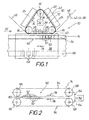
- FIG. 1 schematically shows an embodiment of the embossing device 10 with a stamping station 12 and a transport device 14.
- the embossing station 12 has two spaced apart support rollers 16 and a guide roller 18.
- the support rollers 16 and the guide roller 18 are arranged in a common plane parallel to each other in a parallel triangle in a triangle, preferably in an isosceles triangle.
- To the support rollers 16 and the guide roller 18 passes an embossing belt 20.
- the embossing belt 20 can be heated by means of a heating device 22 which has two heating elements 24.
- an embossing path 26 of the embossing belt 20 is determined.
- stabilizing rollers 28 are provided along the embossing path 26 at the embossing station, which bear against the back 30 of the endless embossing belt 20.
- the embossing belt 20 is drivable by means of a first drive means 32, so that the embossing belt 20 rotates about the support rollers 16 and the guide roller 18 at a certain feed rate. This feed rate is indicated by the arrow 34.
- the first drive device 32 is operatively connected to the deflection roller 18, for example. This is illustrated by the arrow 36.
- the transport device 14 of the embossing device 10 serves to hold and to the defined feed of a dimensionally stable substrate body 38 to be embossed 10, for example, the respective narrow side 40 of the dimensionally stable substrate body 38 with the transfer layer 42 of a stamping foil 44, which is in particular a hot stamping foil can, to imprint.
- the embossing foil 44 consisting of the carrier foil 46 and the decorative transfer layer 42, is fed to the embossing station 10 at a speed corresponding to the feed rate 34 of the embossing belt 20. This is indicated by the arrow 48.
- the transfer layer 42 is detached from the carrier foil 46 of the embossing foil 44 and transferred to the narrow side 40 of the dimensionally stable substrate body 38.
- the carrier foil 46 of the stamping foil 44 is then dispensed from the embossing station 12.
- the transport device 14 By suitable design of the transport device 14, for example, it is also possible to emboss a dimensionally stable substrate body 38 along its entire peripheral edge in one operation. In this case, for example, the transport device 14 is not only suitable for linear advancement of the substrate body 38 but also for rotation thereof.
- the transport device has a clamping device 50 with clamping elements 52 (see in particular also FIGS Figures 2 and 3 ), which form two mutually adjacent endless organs 54.
- the clamping elements 52 for example, each hinged together.
- the two endless organs 54 are adjacent to each other arranged such that the clamping elements 52 form a common clamping path 60 along which the dimensionally stable to be embossed Substrate body 38 is reliably held and transported by means of the transport device 14.
- the transport device 14 has a second drive device 62 (see FIG. FIG. 2 ), which is operatively connected to the pulleys 58 of the two endless members 54, for example. This operative connection is indicated by the angled arrows 64.
- the transport device 14 is, for example, in addition to the two endless organs 54 formed with a support device 66, for example, has bearing rollers 68, which rests defined on each of the dimensionally stable substrate body 38 to be embossed, as well as the FIG. 3 illustrated schematically.
- FIG. 3 also illustrates schematically that the embossing station 12 is adjustable with respect to the transport device 14 for each dimensionally stable substrate body 38 to be embossed in two mutually perpendicular directions in space. This is indicated by the arrow 70 and by the arrow 72.
- the arrow 70 illustrates the delivery of the embossing station 12 in the horizontal direction towards the dimensionally stable substrate body 38 to be embossed and away therefrom
- the arrow 72 illustrates the adjustability of the embossing station 12 in the vertical direction, ie in height relative to the dimensionally stable substrate body 38 to be embossed
- the arcuate arrow 74 illustrates the pivotability of the embossing station 12 about a pivot axis oriented parallel to the feed direction of the transport device 14.
- the feed direction of the transport device 14 is in the Figures 1 and 2 indicated by the arrows 76.
- the feed rate of the transport device 14 in the direction of arrow 76 corresponds to Feed rate 34 of the embossing belt 20 and the speed 48 of the stamping foil 44th
- FIG. 4 illustrates sectionally one on its narrow side 40 to be embossed dimensionally stable substrate body 38.
- the narrow side 40 is convex, ie convex, profiled.
- the embossing belt 20 is formed on its embossing side 78 with a profile 80 adapted to the profile of the narrow side 40.
- FIG. 5 shows cut off a dimensionally stable substrate body 38 in the form of a board or panel with a spring 82 and a groove 84 adapted thereto and chamfer surfaces 86, which with a corresponding stamping foil 44 (see FIG. FIG. 1 ) should be embossed.
- the embossing band 20 is profiled on its embossing side 78 corresponding to a rib-shaped bead 88.
- the embossing belt 20 can be correspondingly profiled on its embossing side 78.
Landscapes
- Shaping Of Tube Ends By Bending Or Straightening (AREA)
- Press Drives And Press Lines (AREA)
- Perforating, Stamping-Out Or Severing By Means Other Than Cutting (AREA)
- Decoration By Transfer Pictures (AREA)
- Confectionery (AREA)
- Delivering By Means Of Belts And Rollers (AREA)
- Credit Cards Or The Like (AREA)
- Machines For Manufacturing Corrugated Board In Mechanical Paper-Making Processes (AREA)
Description
- Die Erfindung betrifft eine Prägevorrichtung zum Übertragen einer Übertragungslage einer Prägefolie auf einen formstabilen Substratkörper, mit einer Prägestation mit zwei voneinander beabstandeten Stützwalzen, um die ein Prägeband umläuft, wobei durch die Stützwalzen eine Prägestrecke des Prägebandes bestimmt ist, und mit einer zum Transport des zu beprägenden formstabilen Substratkörpers vorgesehenen Transporteinrichtung, die zur Prägestrecke parallel und in der Nachbarschaft der Prägestation vorgesehen ist, wobei das Prägeband und die Transporteinrichtung simultan mit der gleichen Vorschubgeschwindigkeit angetrieben werden.
- Eine derartige Prägevorrichtung ist aus der
DE 41 21 766 C2 bekannt. Bei der dortgenannten Materialbahn handelt es sich um eine flexible Materialbahn oder um eine nur bedingt flexible oder nicht flexible Materialbahn. Die Prägevorrichtung weist eine beheizte Stützeinrichtung und eine Andruckrollenanordnung auf. Die Materialbahn und die Prägefolie werden durch eine zwischen der Stützeinrichtung und der Andruckrollenanordnung bestimmte Prägestrecke hindurchtransportiert. Die Stützeinrichtung dieser bekannten Prägevorrichtung weist mindestens zwei voneinander beabstandete und zueinander zumindest achsparallele Stützwalzen auf, um die ein mittels eines Antriebs angetriebenes beheiztes endloses Stützkörperband umläuft. Die Prägestrecke weist eine Kontaktlänge auf, die durch den Achsabstand zwischen den beiden voneinander am weitesten entfernten Stützwalzen definiert ist. Jeder der beiden Stützwalzen oder zumindest den beiden voneinander am weitesten entfernten Stützwalzen ist mindestens eine Andruckrolle der Andruckrollenanordnung zugeordnet, - Die
DE 100 37 643 A1 beschreibt eine Prägemaschine zum Drucken und/oder Prägen einer Prägefolie auf ein geeignetes Material, mit einem ortsfest in der Prägemaschine drehbar gelagerten Druckzylinder, und mit einem in der Prägemaschine zwischen einer Anfangs- und einer Endposition horizontal unter dem Druckzylinder verfahrbaren Druckstempel mit einer Heizeinrichtung. Die Prägefolie ist von einer Vorratsrolle an der dem Druckzylinder abgewandten Seite des Stempels abwickelbar und unterhalb der Oberfläche des Stempels zurück zu einer Aufwickeleinrichtung an der dem Druckzylinder abgewandten Seite des Stempels geführt. Zwischen der Vorratsrolle und dem Stempel ist in Vorschubrichtung der Prägefolie gesehen eine Vorschubeinrichtung für die Prägefolie angeordnet. - Die
DE 25 53 802 A1 beschreibt eine Doppelband-Presse mit zwei umlaufenden Pressbändem, die eine Oberflächenstruktur aufweisen, um in das durch die Presse laufende Pressgut eine Oberflächenstruktur mechanisch einzuprägen. Zusätzlich kann dabei zu kaschierendes Material aufgepresst werden. - Der Erfindung liegt die Aufgabe zugrunde, eine Prägevorrichtung der eingangs genannten Art zu schaffen, mit der formstabile Substratkörper wie Tischplatten, Boden-, Wand- oder Deckenbretter oder -paneele mit relativ hoher Prägegeschwindigkeit mit einer Prägefolie beprägt werden können.
- Diese Aufgabe wird erfindungsgemäß durch die Merkmale des Anspruches 1 gelöst. Hierbei ist vorgesehen, daß die Transporteinrichtung eine Befestigungseinrichtung mit Befestigungselementen aufweist, die mindestens ein Endlosorgan bilden, durch das mindestens eine zur Prägestrecke parallele Befestigungsstrecke bestimmt ist.
- Bei der erfindungsgemäßen Prägevorrichtung kann die Befestigungseinrichtung von einer Klemmeinrichtung mit Klemmelementen gebildet sein, die zwei zueinander benachbarte Endlosorgane bilden, durch die eine gemeinsame, zur Prägestrecke parallele Klemmstrecke bestimmt ist. Die Klemmelemente können beispielsweise miteinander zum jeweiligen Endlosorgan gelenkig verbunden sein. Eine andere Möglichkeit besteht beispielsweise darin, daß die Befestigungseinrichtung der Transporteinrichtung anstelle von Klemmelementen Saugelemente aufweist, die miteinander gelenkig verbunden ein einziges Endlosorgan bilden. Der Transporteinrichtung können auch zwei Prägestationen zugeordnet sein, die sich seitlich gegenüberliegen.
- Bei der erfindungsgemäßen Prägevorrichtung ist die Prägestation ähnlich wie bei der Prägevorrichtung gemäß der oben zitierten
DE 41 21 766 C2 ausgebildet. Die erfindungsgemäße Prägevorrichtung weist jedoch keine Andruckrollen auf und ist insofern anders gestaltet als die Prägevorrichtung gemäß derDE 41 21 766 C2 . Mit Hilfe der erfindungsgemäßen Prägevorrichtung ist es einfach und mit hoher Produktivität möglich, formstabile Substratkörper in Gestalt von Brettern, Platten, Tafeln oder Paneelen mit der Übertragungslage einer Prägefolie, insbesondere Heißprägefolie, zu beprägen. - Bei der erfindungsgemäßen Prägevorrichtung hat es sich - wie bei der Prägevorrichtung gemäß der
DE 41 21 766 C2 - als zweckmäßig erwiesen, wenn die Prägestation eine Umlenkwalze aufweist, die mit den beiden Stützwalzen in einer gemeinsamen Ebene in einem Dreieck vorgesehen ist und um die das Prägeband umgelenkt ist. Durch eine solche Ausbildung ist es einfach und platzsparend möglich, daß dem Prägeband eine Heizeinrichtung zugeordnet ist, die von einem Paar Heizelemente gebildet ist, die an den Schenkelabschnitten zwischen der jeweiligen Stützwalze und der gemeinsamen Umlenkwalze dem Prägeband zugeordnet sind, um dieses optimal zu beheizen. - Bei der erfindungsgemäßen Prägevorrichtung ist es zweckmäßig, wenn das Prägeband mittels einer ersten Antriebseinrichtung und die Transporteinrichtung mittels einer zweiten Antriebseinrichtung simultan, aufeinander abgestimmt, angetrieben werden, so daß das Prägeband und die Transporteinrichtung die gleiche Vorschubgeschwindigkeit besitzen. Das ist durch geeignete Steuerung bzw. Kopplung zwischen der ersten und der zweiten Antriebseinrichtung realisierbar.
- Bei der erfindungsgemäßen Prägevorrichtung hat es sich als vorteilhaft erwiesen, wenn das Prägeband an seiner der Transporteinrichtung zugewandten Prägeseite mit einer an den zu beprägenden Substratkörper angepaßten Profilierung ausgebildet ist. Erfindungsgemäß ist es einfach möglich, ein Prägeband einer bestimmten Profilierung durch ein anderes Prägeband einer anderen Profilierung zu ersetzen, um entsprechende formstabile Substratkörper auf optimale Weise mit der Übertragungslage einer Prägefolie zu beprägen.
- Zweckmäßigerweise ist die Prägestation in Bezug auf die Transporteinrichtung verstellbar. Bei dieser Verstellbarkeit handelt es sich insbesondere um eine Verstellbarkeit zur Transporteinrichtung hin und von der Transporteinrichtung weg, d.h. in horizontaler Richtung und um eine Verstellbarkeit in vertikaler Richtung.
- Um verschieden profilierte formstabile Platten- bzw. brettförmige Substratkörper an ihren Schmalseiten wunschgemäß mit einer Prägefolie beprägen zu können, ist es zweckmäßig, wenn die Prägestation um eine zur Vorschubrichtung der Transporteinrichtung parallel orientierte Schwenkachse verschwenkbar ist.
- Um ein Aufwölben des Prägebandes entlang der Prägestrecke zwischen den beiden Stützwalzen, d.h. ein Entfernen des Prägebandes von dem zu beprägenden formstabilen Substratkörper entlang der Prägestrecke zu vermeiden, kann zwischen den beiden Stützwalzen entlang der Prägestrecke mindestens eine am Prägeband anliegende Stabilisierungswalze vorgesehen sein. Mit Hilfe dieser mindestens einen Stabilisierungswalze wird erreicht, daß das Prägeband entlang der Prägestrecke am zu beprägenden Substratkörper zuverlässig anliegt, so daß der jeweilige formstabile Substratkörper exakt beprägt wird.
- Weitere Einzelheiten, Merkmale und Vorteile ergeben sich aus der nachfolgenden Beschreibung eines in der Zeichnung schematisch dargestellten Ausführungsbeispieles der erfindungsgemäßen Prägevorrichtung bzw. wesentlicher Einzelheiten derselben.
- Es zeigen:
- Figur 1
- eine schematische Draufsicht auf eine Ausführungsform der Prägevorrichtung,
- Figur 2
- eine schematische Seitenansicht der Transporteinrichtung der Prägevorrichtung gemäß
Figur 1 , - Figur 3
- eine schematische Vorderansicht der Prägevorrichtung in Blickrichtung des Pfeiles III in
Figur 1 , - Figur 4
- abschnittweise einen zu beprägenden formstabilen Substratkörper und davon beabstandet ein zugehöriges, passend profiliertes Prägeband in einer Querschnittsdarstellung, und
- Figur 5
- eine der
Figur 4 ähnliche Darstellung eines anders profilierten Prägebandes für einen anderen zu beprägenden formstabilen Substratkörper. -
Figur 1 zeigt schematisch eine Ausbildung der Prägevorrichtung 10 mit einer Prägestation 12 und eine Transporteinrichtung 14. Die Prägestation 12 weist zwei voneinander beabstandete Stützwalzen 16 und eine Umlenkwalze 18 auf. Die Stützwalzen 16 und die Umlenkwalze 18 sind in einer gemeinsamen Ebene zueinander achsparallel in einem Dreieck, vorzugsweise in einem gleichschenkeligen Dreieck, angeordnet. Um die Stützwalzen 16 und die Umlenkwalze 18 läuft ein Prägeband 20 um. Das Prägeband 20 ist mittels einer Heizeinrichtung 22 beheizbar, die zwei Heizelemente 24 aufweist. - Durch die beiden voneinander beabstandeten Stützwalzen 16 ist eine Prägestrecke 26 des Prägebandes 20 bestimmt. Zwischen den beiden Stützwalzen 16 sind entlang der Prägestrecke 26 an der Prägestation 12 Stabilisierungswalzen 28 vorgesehen, die an der Rückseite 30 des endlosen Prägebandes 20 anliegen.
- Das Prägeband 20 ist mittels einer ersten Antriebseinrichtung 32 antreibbar, so daß das Prägeband 20 um die Stützwalzen 16 und die Umlenkwalze 18 mit einer bestimmten Vorschubgeschwindigkeit umläuft. Diese Vorschubgeschwindigkeit ist durch den Pfeil 34 angedeutet.
- Die erste Antriebseinrichtung 32 ist beispielsweise mit der Umlenkwalze 18 wirkverbunden. Das ist durch den Pfeil 36 verdeutlicht.
- Die Transporteinrichtung 14 der Prägevorrichtung 10 dient zum Festhalten und zum definierten Vorschub eines zu beprägenden formstabilen Substratkörpers 38 zur Prägevorrichtung 10, um beispielsweise die jeweilige Schmalseite 40 des formstabilen Substratkörpers 38 mit der Übertragungslage 42 einer Prägefolie 44 , bei der es sich insbesondere um eine Heißprägefolie handeln kann, zu beprägen. Die Prägefolie 44, bestehend aus der Trägerfolie 46 und der dekorativen Übertragungslage 42, wird der Prägestation 10 mit einer der Vorschubgeschwindigkeit 34 des Prägebandes 20 entsprechenden Geschwindigkeit zugeführt. Das ist durch den Pfeil 48 angedeutet. Entlang der Prägestrecke 26 wird die Übertragungslage 42 von der Trägerfolie 46 der Prägefolie 44 abgelöst und auf die Schmalseite 40 des formstabilen Substratkörpers 38 übertragen. Nach der Formstrecke 26 wird dann also nur die Trägerfolie 46 der Prägefolie 44 aus der Prägestation 12 ausgegeben.
- Durch geeignete Gestaltung der Transporteinrichtung 14 ist es beispielsweise auch möglich, einen formstabilen Substratkörper 38 entlang seines gesamten Umfangsrandes in einem Arbeitsgang zu beprägen. In diesem Falle ist die Transporteinrichtung 14 also beispielsweise nicht nur zum linearen Vorschub des Substratkörpers 38 sondern außerdem auch zur Drehung desselben geeignet.
- Bei der Ausbildung der Prägevorrichtung 10 gemäß
Figur 1 weist die Transporteinrichtung eine Klemmeinrichtung 50 mit Klemmelementen 52 auf (sh. insbesondere auch dieFiguren 2 und3 ), die zwei zueinander benachbarte Endlosorgane 54 bilden. Zu diesem Zwecke sind die Klemmelemente 52 beispielsweise miteinander jeweils gelenkig verbunden. In denFiguren 1 und 2 sind jeweils nur einige der Klemmelemente 52 schematisch verdeutlicht, die um Umlenkrollen 56 und 58 umgelenkt sind. Die beiden Endlosorgane 54 sind zueinander benachbart derartig angeordnet, daß die Klemmelemente 52 eine gemeinsame Klemmstrecke 60 bilden, entlang der der zu beprägende formstabile Substratkörper 38 zuverlässig festgehalten und mit Hilfe der Transporteinrichtung 14 transportiert wird. Zu diesem Zwecke weist die Transporteinrichtung 14 eine zweite Antriebseinrichtung 62 auf (sh.Figur 2 ), die beispielsweise mit den Umlenkrollen 58 der beiden Endlosorgane 54 wirkverbunden ist. Diese Wirkverbindung ist durch die abgewinkelten Pfeile 64 angedeutet. - Die Transporteinrichtung 14 ist beispielsweise zusätzlich zu den beiden Endlosorganen 54 mit einer Auflagereinrichtung 66 ausgebildet, die beispielsweise Lagerrollen 68 aufweist, auf welchen der jeweils zu beprägende formstabile Substratkörper 38 definiert aufliegt, wie auch die
Figur 3 schematisch verdeutlicht. - In den
Figuren 1, 2 und3 sind gleiche Einzelheiten jeweils mit denselben Bezugsziffern bezeichnet, so daß es sich erübrigt, in Verbindung mit diesen Figuren alle Einzelheiten jeweils detailliert zu beschreiben. - Die
Figur 3 verdeutlicht außerdem schematisch, daß die Prägestation 12 in bezug auf die Transporteinrichtung 14 für den jeweils zu beprägenden formstabilen Substratkörper 38 in zwei zueinander senkrechten Raumrichtungen verstellbar ist. Das ist durch den Pfeil 70 und durch den Pfeil 72 angedeutet. Der Pfeil 70 verdeutlicht die Zustellung der Prägestation 12 in horizontaler Richtung hin zum zu beprägenden formstabilen Substratkörper 38 und von diesem weg und der Pfeil 72 verdeutlicht die Verstellbarkeit der Prägestation 12 in vertikaler Richtung, d.h. in der Höhe in bezug auf den zu beprägenden formstabilen Substratkörper 38. Der bogenförmige Pfeil 74 verdeutlicht die Verschwenkbarkeit der Prägestation 12 um eine zur Vorschubrichtung der Transporteinrichtung 14 parallel orientierte Schwenkachse. Die Vorschubrichtung der Transporteinrichtung 14 ist in denFiguren 1 und 2 durch die Pfeile 76 angedeutet. Die Vorschubgeschwindigkeit der Transporteinrichtung 14 in Richtung des Pfeiles 76 entspricht der Vorschubgeschwindigkeit 34 des Prägebandes 20 und der Geschwindigkeit 48 der Prägefolie 44. -
Figur 4 verdeutlicht abschnittweise einen an seiner Schmalseite 40 zu beprägenden formstabilen Substratkörper 38. Die Schmalseite 40 ist ballig, d.h. konvex, profiliert. Entsprechend ist das Prägeband 20 an seiner Prägeseite 78 mit einer an das Profil der Schmalseite 40 angepaßten Profilierung 80 ausgebildet. -
Figur 5 verdeutlicht abgeschnitten einen formstabilen Substratkörper 38 in Form eines Brettes oder Paneeles mit einer Feder 82 und einer daran angepaßten Nut 84 und Fasenflächen 86, die mit einer entsprechenden Prägefolie 44 (sh.Figur 1 ) beprägt werden sollen. Zu diesem Zwecke, d.h. zum Beprägen der jeweiligen Fasenfläche 86, ist das Prägeband 20 an seiner Prägeseite 78 entsprechend mit einem rippenförmigen Wulst 88 profiliert. - Dem jeweils zu beprägenden formstabilen Substratkörper 38 entsprechend kann das Prägeband 20 an seiner Prägeseite 78 entsprechend passend profiliert sein.
Claims (12)
- Prägevorrichtung zum Übertragen einer Übertragungslage (42) einer Prägefolie (44) auf einen formstabilen Substratkörper (38) mit einer Prägestation (12) mit zwei voneinander beabstandeten Stützwalzen (16), um die ein Prägeband (20) umläuft, wobei durch die Stützwalzen (16) eine Prägestrecke (26) des Prägebandes (20) bestimmt ist, und mit einer zum Transport des zu beprägenden formstabilen Substratkörpers (38) vorgesehenen Transporteinrichtung (14), die zur Prägestrecke (26) parallel und in der Nachbarschaft der Prägestation (12) vorgesehen ist, wobei das Prägeband (20) und die Transporteinrichtung (14) simultan mit der gleichen Vorschubgeschwindigkeit (34) angetrieben werden,
dadurch gekennzeichnet ,
daß die Transporteinrichtung (14) eine Befestigungseinrichtung (50) mit Befestigungselementen (52) aufweist, die mindestens ein Endlosorgan (54) bilden, durch das mindestens eine zur Prägestrecke (26) parallele Befestigungsstrecke (60) bestimmt ist. - Prägevorrichtung nach Anspruch 1,
dadurch gekennzeichnet,
daß die Befestigungseinrichtung (50) von einer Klemmeinrichtung mit Klemmelementen (52) gebildet ist, die zwei zueinander benachbarte Endlosorgane (54) bilden, durch die eine gemeinsame, zur Prägestrecke (26) parallele Klemmstrecke für den zu beprägenden Substratkörper (38) bestimmt ist. - Prägevorrichtung nach Anspruch 2,
dadurch gekennzeichnet,
daß die Klemmelemente (52) gelenkig zum jeweiligen Endlosorgan (54) verbunden sind. - Prägevorrichtung nach Anspruch 1,
dadurch gekennzeichnet,
daß die Befestigungseinrichtung (50) Saugelemente aufweist, die miteinander gelenkig zu einem einzigen Endlosorgan (54) verbunden sind. - Prägerrorrichtung nach einem der vorhergehenden Ansprüche,
dadurch gekennzeichnet ,
daß die Prägestation (12) eine Umlenkwalze (18) aufweist, die mit den beiden Stützwalzen (16) in einer gemeinsamen Ebene in einem Dreieck vorgesehen ist und um die das Prägeband (20) umgelenkt ist. - Prägevorrichtung nach einem der vorhergehenden Ansprüche
dadurch gekennzeichnet ,
daß dem Prägeband (20) eine Heizeinrichtung (22) zugeordnet ist. - Prägevorrichtung nach einem der vorhergehenden Ansprüche,
dadurch gekennzeichnet ,
daß das Prägeband (20) mittels einer ersten Antriebseinrichtung (32) und die Transporteinrichtung (14) mittels einer zweiten Antriebseinrichtung (62) simultan, aufeinander abgestimmt, angetrieben werden, - Prägevorrichtung nach einem der vorhergehenden Ansprüche,
dadurch gekennzeichnet ,
daß das Prägeband (20) an seiner der Transporteinrichtung (14) zugewandten Prägeseite (78) mit einer an den zu beprägenden Substratkörper (38) angepaßten Profilierung (80) ausgebildet ist. - Prägevorrichtung nach einem der vorhergehenden Ansprüche,
dadurch gekennzeichnet ,
daß die Prägestation (12) in bezug auf die Transporteinrichtung (14) verstellbar ist. - Prägevorrichtung nach Anspruch 9,
dadurch gekennzeichnet,
daß die Prägestation (12) um eine zur Vorschubrichtung (76) der Transporteinrichtung (14) parallel orientierte Schwenkachse verschwenkbar ist. - Prägevorrichtung nach einem der vorhergehenden Ansprüche,
dadurch gekennzeichnet,
daß zwischen den beiden Stützwalzen (16) entlang der Prägestrecke (26) mindestens eine am Prägeband (20) anliegende Stabilisierungswalze (28) vorgesehen ist. - Prägevorrichtung nach einem der vorhergehenden Ansprüche,
dadurch gekennzeichnet,
daß der Transporteinrichtung (14) zwei Prägestationen zugeordnet sind, die sich seitlich gegenüberliegen.
Applications Claiming Priority (3)
| Application Number | Priority Date | Filing Date | Title |
|---|---|---|---|
| DE10216139 | 2002-04-12 | ||
| DE10216139A DE10216139C1 (de) | 2002-04-12 | 2002-04-12 | Prägevorrichtung |
| PCT/DE2003/001042 WO2003086779A2 (de) | 2002-04-12 | 2003-03-29 | Transporteinrichtung in einer prägevorrichtung |
Publications (2)
| Publication Number | Publication Date |
|---|---|
| EP1497144A2 EP1497144A2 (de) | 2005-01-19 |
| EP1497144B1 true EP1497144B1 (de) | 2011-01-05 |
Family
ID=29224478
Family Applications (1)
| Application Number | Title | Priority Date | Filing Date |
|---|---|---|---|
| EP03718645A Expired - Lifetime EP1497144B1 (de) | 2002-04-12 | 2003-03-29 | Prägevorrichtung mit einer transporteinrichtung |
Country Status (10)
| Country | Link |
|---|---|
| US (1) | US7357168B2 (de) |
| EP (1) | EP1497144B1 (de) |
| JP (1) | JP4034739B2 (de) |
| CN (1) | CN100431853C (de) |
| AT (1) | ATE494157T1 (de) |
| AU (1) | AU2003222731A1 (de) |
| DE (2) | DE10216139C1 (de) |
| MY (1) | MY138772A (de) |
| RU (1) | RU2283780C2 (de) |
| WO (1) | WO2003086779A2 (de) |
Families Citing this family (18)
| Publication number | Priority date | Publication date | Assignee | Title |
|---|---|---|---|---|
| DE10352700B3 (de) * | 2003-11-12 | 2005-01-20 | Leonhard Kurz Gmbh & Co. Kg | Prägestation für eine Prägevorrichtung |
| BE1016846A3 (nl) | 2005-11-09 | 2007-08-07 | Flooring Ind Ltd | Vloerbekleding, vloerpanelen en werkwijze voor het vervaardigen van vloerpanelen. |
| JP2008068285A (ja) * | 2006-09-14 | 2008-03-27 | Nissan Motor Co Ltd | 微細凹部加工装置及び微細凹部加工方法 |
| DE102006056701B4 (de) | 2006-11-30 | 2008-08-28 | Leonhard Kurz Gmbh & Co. Kg | Prägevorrichtung |
| DE102007058815B3 (de) * | 2007-12-05 | 2009-04-02 | Leonhard Kurz Stiftung & Co. Kg | Vorrichtung zum Beprägen von entlang einer Transportstrecke geführten Werkstücken mit einer Folie |
| DE102008013279A1 (de) | 2008-03-08 | 2009-09-10 | Leonhard Kurz Stiftung & Co. Kg | Verfahren und Vorrichtung zum Beprägen von Werkstücken |
| EP2113393B1 (de) | 2008-04-29 | 2012-04-11 | Flooring Industries Limited, SARL | Bodenpaneel, Verfahren zur Herstellung von Bodenpaneelen und Transferfolie |
| DE102009006535B3 (de) * | 2009-01-28 | 2010-07-15 | Leonhard Kurz Stiftung & Co. Kg | Prägevorrichtung und Prägeverfahren |
| JP5428549B2 (ja) * | 2009-06-05 | 2014-02-26 | 東洋製罐株式会社 | エンボス加工装置及びエンボス加工方法 |
| CN101638839B (zh) * | 2009-07-14 | 2012-05-30 | 东莞贰发毛绒有限公司 | 一种植绒产品的加工工艺及压花机 |
| AT513128B1 (de) * | 2012-07-24 | 2014-02-15 | Berndorf Band Gmbh | Verfahren zum Strukturieren eines Pressbandes |
| CN102909946A (zh) * | 2012-10-17 | 2013-02-06 | 上海联净电子科技有限公司 | 一种单次模压连续印刷工艺及装置 |
| DE102013102984B4 (de) | 2013-03-22 | 2015-01-22 | Leonhard Kurz Stiftung & Co. Kg | Folienprägeeinrichtung |
| DE202014005743U1 (de) | 2014-07-09 | 2014-07-24 | Hansgrohe Se | Prägeeinrichtung |
| CN104669392B (zh) * | 2015-03-02 | 2017-03-01 | 盐城鼎恒机械有限公司 | 一种仿古木地板加工机 |
| CN110722039B (zh) * | 2019-10-22 | 2024-02-23 | 中国科学院合肥物质科学研究院 | 一种工件冲压自动搬运及覆膜系统 |
| CN111923643A (zh) * | 2020-07-09 | 2020-11-13 | 柳艳姣 | 一种铝板加热压花装置 |
| CN115139691B (zh) * | 2022-05-06 | 2024-08-23 | 海啊科技股份有限公司 | 一种汽车脚垫的压纹设备 |
Family Cites Families (10)
| Publication number | Priority date | Publication date | Assignee | Title |
|---|---|---|---|---|
| DE2553802A1 (de) | 1975-11-29 | 1977-06-02 | Friz Gmbh Adolf | Band-praege-presse |
| DE2721980C3 (de) | 1977-05-14 | 1981-07-16 | Fa. Leonhard Kurz, 8510 Fürth | Prägefolien-Zuführvorrichtung für eine Prägemaschine |
| US4517235A (en) | 1982-11-16 | 1985-05-14 | Nevamar Corporation | Transfer coating of abrasion-resistant layers |
| DE4121766A1 (de) * | 1991-07-01 | 1993-01-07 | Kurz Leonhard Fa | Vorrichtung zum uebertragen eines dekors von einer praegefolie auf eine materialbahn |
| US5421951A (en) * | 1991-10-16 | 1995-06-06 | Trus Joist Macmillan | Platen press |
| RU2041818C1 (ru) * | 1992-06-17 | 1995-08-20 | Фирма "Эмиф" | Устройство для прессования изделий |
| KR100381746B1 (ko) * | 1997-04-25 | 2003-04-26 | 메소나이트 인터내셔널 코포레이션 | 중공 코어 도어 및 그의 제조 방법 |
| CN2328443Y (zh) * | 1997-10-17 | 1999-07-14 | 王本华 | 金属管压花装置 |
| CN2378185Y (zh) * | 1999-05-18 | 2000-05-17 | 林典来 | 一种金属箔、纸复合材料的压花装置 |
| DE10037643A1 (de) * | 2000-07-31 | 2002-02-21 | Ms Praegesysteme Gmb | Prägemaschine für Prägefolien |
-
2002
- 2002-04-12 DE DE10216139A patent/DE10216139C1/de not_active Expired - Fee Related
-
2003
- 2003-03-29 CN CNB038081628A patent/CN100431853C/zh not_active Expired - Fee Related
- 2003-03-29 DE DE50313395T patent/DE50313395D1/de not_active Expired - Lifetime
- 2003-03-29 RU RU2004133058/12A patent/RU2283780C2/ru active
- 2003-03-29 JP JP2003583765A patent/JP4034739B2/ja not_active Expired - Fee Related
- 2003-03-29 US US10/510,922 patent/US7357168B2/en not_active Expired - Lifetime
- 2003-03-29 EP EP03718645A patent/EP1497144B1/de not_active Expired - Lifetime
- 2003-03-29 WO PCT/DE2003/001042 patent/WO2003086779A2/de not_active Ceased
- 2003-03-29 AT AT03718645T patent/ATE494157T1/de active
- 2003-03-29 AU AU2003222731A patent/AU2003222731A1/en not_active Abandoned
- 2003-04-09 MY MYPI20031306A patent/MY138772A/en unknown
Also Published As
| Publication number | Publication date |
|---|---|
| DE10216139C1 (de) | 2003-12-11 |
| CN100431853C (zh) | 2008-11-12 |
| ATE494157T1 (de) | 2011-01-15 |
| US7357168B2 (en) | 2008-04-15 |
| EP1497144A2 (de) | 2005-01-19 |
| RU2004133058A (ru) | 2005-06-27 |
| MY138772A (en) | 2009-07-31 |
| AU2003222731A1 (en) | 2003-10-27 |
| WO2003086779A2 (de) | 2003-10-23 |
| AU2003222731A8 (en) | 2003-10-27 |
| RU2283780C2 (ru) | 2006-09-20 |
| WO2003086779A3 (de) | 2004-01-29 |
| DE50313395D1 (de) | 2011-02-17 |
| US20060108071A1 (en) | 2006-05-25 |
| JP4034739B2 (ja) | 2008-01-16 |
| CN1646333A (zh) | 2005-07-27 |
| JP2005527382A (ja) | 2005-09-15 |
Similar Documents
| Publication | Publication Date | Title |
|---|---|---|
| EP1497144B1 (de) | Prägevorrichtung mit einer transporteinrichtung | |
| DE4138278C2 (de) | Vorrichtung zum Stanzen, Rillen und Perforieren für Bogendruckmaschinen | |
| DE3022525C2 (de) | Verfahren und Vorrichtung zum Aufbringen eines Aufklebers auf eine Endlosbahn | |
| DE1511870B1 (de) | Vorrichtung zum Übertragen von l¦sbar an einem Trägerband angeordneten Heisssiegeletiketten auf Gegenstände | |
| EP3254767A2 (de) | Bodenlegevorrichtung zur herstellung von säcken | |
| EP0687553A2 (de) | Maschine zur Herstellung einer einseitig kaschierten Wellpappebahn | |
| EP2098381A2 (de) | Verfahren und Vorrichtung zum Beprägen von Werkstücken | |
| EP2213475B1 (de) | Prägevorrichtung und Verfahren | |
| DE19539410C2 (de) | Heißprägemaschine zum Einfärben von geprägten Schildern, insbesondere von Kraftfahrzeug-Kennzeichenschildern | |
| DE69104406T2 (de) | Vorrichtung zum Einrütteln von Blättern. | |
| DE1786641C2 (de) | Leimauftragsmaschine für die Herstellung von Wellpappe o.dgl | |
| DE3503715C2 (de) | ||
| DE10159661C1 (de) | Heißprägemaschine mit einer Prägestation | |
| DE4343014C2 (de) | Druckmaschine für Druckpapierblätter | |
| EP2067631B1 (de) | Vorrichtung zum Beprägen mit Prägebändern | |
| DE102006005992B4 (de) | Vorrichtung zum Stanzen von Stanzgut, insbesondere von Folienbahnen oder dergleichen | |
| DE69911812T2 (de) | Klebstoffauftragsvorrichtung- und verfahren | |
| DE102006005991B4 (de) | Vorrichtung zum Ablängen von folienartigen Materialbahnen | |
| DE19618175C1 (de) | Vorrichtung zum Ersetzen einer ersten Bahn durch eine zweite Bahn | |
| DE19948704C1 (de) | Vorrichtung zum Drehen eines Papierstapels | |
| DE4213472A1 (de) | Vorrichtung zum Fördern flexibler Druckformen | |
| DE20205662U1 (de) | Prägevorrichtung | |
| DE102019111857B4 (de) | Heißprägepresse | |
| DE2920261A1 (de) | Kaschiermaschine | |
| DE10009162A1 (de) | Folienprägemaschine |
Legal Events
| Date | Code | Title | Description |
|---|---|---|---|
| PUAI | Public reference made under article 153(3) epc to a published international application that has entered the european phase |
Free format text: ORIGINAL CODE: 0009012 |
|
| 17P | Request for examination filed |
Effective date: 20040925 |
|
| AK | Designated contracting states |
Kind code of ref document: A2 Designated state(s): AT BE BG CH CY CZ DE DK EE ES FI FR GB GR HU IE IT LI LU MC NL PT RO SE SI SK TR |
|
| AX | Request for extension of the european patent |
Extension state: AL LT LV MK |
|
| 17Q | First examination report despatched |
Effective date: 20071106 |
|
| RAP1 | Party data changed (applicant data changed or rights of an application transferred) |
Owner name: LEONHARD KURZ STIFTUNG & CO. KG |
|
| GRAP | Despatch of communication of intention to grant a patent |
Free format text: ORIGINAL CODE: EPIDOSNIGR1 |
|
| RTI1 | Title (correction) |
Free format text: EMBOSSING DEVICE WITH CONVEYANCE DEVICE |
|
| GRAS | Grant fee paid |
Free format text: ORIGINAL CODE: EPIDOSNIGR3 |
|
| GRAA | (expected) grant |
Free format text: ORIGINAL CODE: 0009210 |
|
| AK | Designated contracting states |
Kind code of ref document: B1 Designated state(s): AT BE BG CH CY CZ DE DK EE ES FI FR GB GR HU IE IT LI LU MC NL PT RO SE SI SK TR |
|
| REG | Reference to a national code |
Ref country code: GB Ref legal event code: FG4D Free format text: NOT ENGLISH |
|
| REG | Reference to a national code |
Ref country code: CH Ref legal event code: EP |
|
| REG | Reference to a national code |
Ref country code: IE Ref legal event code: FG4D Free format text: LANGUAGE OF EP DOCUMENT: GERMAN |
|
| REF | Corresponds to: |
Ref document number: 50313395 Country of ref document: DE Date of ref document: 20110217 Kind code of ref document: P |
|
| REG | Reference to a national code |
Ref country code: DE Ref legal event code: R096 Ref document number: 50313395 Country of ref document: DE Effective date: 20110217 |
|
| REG | Reference to a national code |
Ref country code: SE Ref legal event code: TRGR |
|
| REG | Reference to a national code |
Ref country code: NL Ref legal event code: VDEP Effective date: 20110105 |
|
| PG25 | Lapsed in a contracting state [announced via postgrant information from national office to epo] |
Ref country code: SI Free format text: LAPSE BECAUSE OF FAILURE TO SUBMIT A TRANSLATION OF THE DESCRIPTION OR TO PAY THE FEE WITHIN THE PRESCRIBED TIME-LIMIT Effective date: 20110105 |
|
| PG25 | Lapsed in a contracting state [announced via postgrant information from national office to epo] |
Ref country code: GR Free format text: LAPSE BECAUSE OF FAILURE TO SUBMIT A TRANSLATION OF THE DESCRIPTION OR TO PAY THE FEE WITHIN THE PRESCRIBED TIME-LIMIT Effective date: 20110406 Ref country code: PT Free format text: LAPSE BECAUSE OF FAILURE TO SUBMIT A TRANSLATION OF THE DESCRIPTION OR TO PAY THE FEE WITHIN THE PRESCRIBED TIME-LIMIT Effective date: 20110505 Ref country code: ES Free format text: LAPSE BECAUSE OF FAILURE TO SUBMIT A TRANSLATION OF THE DESCRIPTION OR TO PAY THE FEE WITHIN THE PRESCRIBED TIME-LIMIT Effective date: 20110416 |
|
| REG | Reference to a national code |
Ref country code: IE Ref legal event code: FD4D |
|
| PG25 | Lapsed in a contracting state [announced via postgrant information from national office to epo] |
Ref country code: CY Free format text: LAPSE BECAUSE OF FAILURE TO SUBMIT A TRANSLATION OF THE DESCRIPTION OR TO PAY THE FEE WITHIN THE PRESCRIBED TIME-LIMIT Effective date: 20110105 Ref country code: FI Free format text: LAPSE BECAUSE OF FAILURE TO SUBMIT A TRANSLATION OF THE DESCRIPTION OR TO PAY THE FEE WITHIN THE PRESCRIBED TIME-LIMIT Effective date: 20110105 Ref country code: NL Free format text: LAPSE BECAUSE OF FAILURE TO SUBMIT A TRANSLATION OF THE DESCRIPTION OR TO PAY THE FEE WITHIN THE PRESCRIBED TIME-LIMIT Effective date: 20110105 Ref country code: BG Free format text: LAPSE BECAUSE OF FAILURE TO SUBMIT A TRANSLATION OF THE DESCRIPTION OR TO PAY THE FEE WITHIN THE PRESCRIBED TIME-LIMIT Effective date: 20110405 |
|
| PG25 | Lapsed in a contracting state [announced via postgrant information from national office to epo] |
Ref country code: MC Free format text: LAPSE BECAUSE OF NON-PAYMENT OF DUE FEES Effective date: 20110331 Ref country code: EE Free format text: LAPSE BECAUSE OF FAILURE TO SUBMIT A TRANSLATION OF THE DESCRIPTION OR TO PAY THE FEE WITHIN THE PRESCRIBED TIME-LIMIT Effective date: 20110105 Ref country code: IE Free format text: LAPSE BECAUSE OF FAILURE TO SUBMIT A TRANSLATION OF THE DESCRIPTION OR TO PAY THE FEE WITHIN THE PRESCRIBED TIME-LIMIT Effective date: 20110105 Ref country code: DK Free format text: LAPSE BECAUSE OF FAILURE TO SUBMIT A TRANSLATION OF THE DESCRIPTION OR TO PAY THE FEE WITHIN THE PRESCRIBED TIME-LIMIT Effective date: 20110105 |
|
| REG | Reference to a national code |
Ref country code: CH Ref legal event code: PL |
|
| PLBE | No opposition filed within time limit |
Free format text: ORIGINAL CODE: 0009261 |
|
| STAA | Information on the status of an ep patent application or granted ep patent |
Free format text: STATUS: NO OPPOSITION FILED WITHIN TIME LIMIT |
|
| PG25 | Lapsed in a contracting state [announced via postgrant information from national office to epo] |
Ref country code: RO Free format text: LAPSE BECAUSE OF FAILURE TO SUBMIT A TRANSLATION OF THE DESCRIPTION OR TO PAY THE FEE WITHIN THE PRESCRIBED TIME-LIMIT Effective date: 20110105 Ref country code: SK Free format text: LAPSE BECAUSE OF FAILURE TO SUBMIT A TRANSLATION OF THE DESCRIPTION OR TO PAY THE FEE WITHIN THE PRESCRIBED TIME-LIMIT Effective date: 20110105 Ref country code: CZ Free format text: LAPSE BECAUSE OF FAILURE TO SUBMIT A TRANSLATION OF THE DESCRIPTION OR TO PAY THE FEE WITHIN THE PRESCRIBED TIME-LIMIT Effective date: 20110105 |
|
| 26N | No opposition filed |
Effective date: 20111006 |
|
| REG | Reference to a national code |
Ref country code: FR Ref legal event code: ST Effective date: 20111130 |
|
| GBPC | Gb: european patent ceased through non-payment of renewal fee |
Effective date: 20110405 |
|
| PG25 | Lapsed in a contracting state [announced via postgrant information from national office to epo] |
Ref country code: FR Free format text: LAPSE BECAUSE OF NON-PAYMENT OF DUE FEES Effective date: 20110331 Ref country code: CH Free format text: LAPSE BECAUSE OF NON-PAYMENT OF DUE FEES Effective date: 20110331 Ref country code: LI Free format text: LAPSE BECAUSE OF NON-PAYMENT OF DUE FEES Effective date: 20110331 |
|
| REG | Reference to a national code |
Ref country code: DE Ref legal event code: R097 Ref document number: 50313395 Country of ref document: DE Effective date: 20111006 |
|
| PG25 | Lapsed in a contracting state [announced via postgrant information from national office to epo] |
Ref country code: GB Free format text: LAPSE BECAUSE OF NON-PAYMENT OF DUE FEES Effective date: 20110405 |
|
| REG | Reference to a national code |
Ref country code: AT Ref legal event code: MM01 Ref document number: 494157 Country of ref document: AT Kind code of ref document: T Effective date: 20110329 |
|
| PG25 | Lapsed in a contracting state [announced via postgrant information from national office to epo] |
Ref country code: AT Free format text: LAPSE BECAUSE OF NON-PAYMENT OF DUE FEES Effective date: 20110329 |
|
| PG25 | Lapsed in a contracting state [announced via postgrant information from national office to epo] |
Ref country code: LU Free format text: LAPSE BECAUSE OF NON-PAYMENT OF DUE FEES Effective date: 20110329 |
|
| PG25 | Lapsed in a contracting state [announced via postgrant information from national office to epo] |
Ref country code: TR Free format text: LAPSE BECAUSE OF FAILURE TO SUBMIT A TRANSLATION OF THE DESCRIPTION OR TO PAY THE FEE WITHIN THE PRESCRIBED TIME-LIMIT Effective date: 20110105 |
|
| PG25 | Lapsed in a contracting state [announced via postgrant information from national office to epo] |
Ref country code: HU Free format text: LAPSE BECAUSE OF FAILURE TO SUBMIT A TRANSLATION OF THE DESCRIPTION OR TO PAY THE FEE WITHIN THE PRESCRIBED TIME-LIMIT Effective date: 20110105 |
|
| PGFP | Annual fee paid to national office [announced via postgrant information from national office to epo] |
Ref country code: DE Payment date: 20210125 Year of fee payment: 19 Ref country code: SE Payment date: 20210323 Year of fee payment: 19 Ref country code: BE Payment date: 20210322 Year of fee payment: 19 |
|
| PGFP | Annual fee paid to national office [announced via postgrant information from national office to epo] |
Ref country code: IT Payment date: 20210331 Year of fee payment: 19 |
|
| REG | Reference to a national code |
Ref country code: DE Ref legal event code: R119 Ref document number: 50313395 Country of ref document: DE |
|
| REG | Reference to a national code |
Ref country code: BE Ref legal event code: MM Effective date: 20220331 |
|
| PG25 | Lapsed in a contracting state [announced via postgrant information from national office to epo] |
Ref country code: SE Free format text: LAPSE BECAUSE OF NON-PAYMENT OF DUE FEES Effective date: 20220330 Ref country code: DE Free format text: LAPSE BECAUSE OF NON-PAYMENT OF DUE FEES Effective date: 20221001 |
|
| PG25 | Lapsed in a contracting state [announced via postgrant information from national office to epo] |
Ref country code: BE Free format text: LAPSE BECAUSE OF NON-PAYMENT OF DUE FEES Effective date: 20220331 |
|
| PG25 | Lapsed in a contracting state [announced via postgrant information from national office to epo] |
Ref country code: IT Free format text: LAPSE BECAUSE OF NON-PAYMENT OF DUE FEES Effective date: 20220329 |