EP1500366A2 - Saugkopf für Staubsauger - Google Patents
Saugkopf für Staubsauger Download PDFInfo
- Publication number
- EP1500366A2 EP1500366A2 EP03029749A EP03029749A EP1500366A2 EP 1500366 A2 EP1500366 A2 EP 1500366A2 EP 03029749 A EP03029749 A EP 03029749A EP 03029749 A EP03029749 A EP 03029749A EP 1500366 A2 EP1500366 A2 EP 1500366A2
- Authority
- EP
- European Patent Office
- Prior art keywords
- agitator
- suction head
- fixed
- driving
- suction
- Prior art date
- Legal status (The legal status is an assumption and is not a legal conclusion. Google has not performed a legal analysis and makes no representation as to the accuracy of the status listed.)
- Granted
Links
Images



Classifications
-
- A—HUMAN NECESSITIES
- A47—FURNITURE; DOMESTIC ARTICLES OR APPLIANCES; COFFEE MILLS; SPICE MILLS; SUCTION CLEANERS IN GENERAL
- A47L—DOMESTIC WASHING OR CLEANING; SUCTION CLEANERS IN GENERAL
- A47L9/00—Details or accessories of suction cleaners, e.g. mechanical means for controlling the suction or for effecting pulsating action; Storing devices specially adapted to suction cleaners or parts thereof; Carrying-vehicles specially adapted for suction cleaners
- A47L9/02—Nozzles
- A47L9/04—Nozzles with driven brushes or agitators
-
- A—HUMAN NECESSITIES
- A47—FURNITURE; DOMESTIC ARTICLES OR APPLIANCES; COFFEE MILLS; SPICE MILLS; SUCTION CLEANERS IN GENERAL
- A47L—DOMESTIC WASHING OR CLEANING; SUCTION CLEANERS IN GENERAL
- A47L9/00—Details or accessories of suction cleaners, e.g. mechanical means for controlling the suction or for effecting pulsating action; Storing devices specially adapted to suction cleaners or parts thereof; Carrying-vehicles specially adapted for suction cleaners
- A47L9/02—Nozzles
- A47L9/04—Nozzles with driven brushes or agitators
- A47L9/0405—Driving means for the brushes or agitators
- A47L9/0411—Driving means for the brushes or agitators driven by electric motor
-
- A—HUMAN NECESSITIES
- A47—FURNITURE; DOMESTIC ARTICLES OR APPLIANCES; COFFEE MILLS; SPICE MILLS; SUCTION CLEANERS IN GENERAL
- A47L—DOMESTIC WASHING OR CLEANING; SUCTION CLEANERS IN GENERAL
- A47L9/00—Details or accessories of suction cleaners, e.g. mechanical means for controlling the suction or for effecting pulsating action; Storing devices specially adapted to suction cleaners or parts thereof; Carrying-vehicles specially adapted for suction cleaners
- A47L9/02—Nozzles
- A47L9/04—Nozzles with driven brushes or agitators
- A47L9/0427—Gearing or transmission means therefor
-
- A—HUMAN NECESSITIES
- A47—FURNITURE; DOMESTIC ARTICLES OR APPLIANCES; COFFEE MILLS; SPICE MILLS; SUCTION CLEANERS IN GENERAL
- A47L—DOMESTIC WASHING OR CLEANING; SUCTION CLEANERS IN GENERAL
- A47L9/00—Details or accessories of suction cleaners, e.g. mechanical means for controlling the suction or for effecting pulsating action; Storing devices specially adapted to suction cleaners or parts thereof; Carrying-vehicles specially adapted for suction cleaners
- A47L9/02—Nozzles
- A47L9/04—Nozzles with driven brushes or agitators
- A47L9/0461—Dust-loosening tools, e.g. agitators, brushes
- A47L9/0483—Reciprocating or oscillating tools, e.g. vibrators, agitators, beaters
Definitions
- the present invention relates to a suction head for a vacuum cleaner, and more particularly, to a suction head for a vacuum cleaner which can efficiently suck alien substances and prevent the alien substances from getting tangled.
- a conventional vacuum cleaner includes a main body 1 having a fan motor for generating a suction force, a suction tube 2 connected to the suction side of the main body 1, a connection tube 4 connected to the suction tube 2, and a suction head 5 connected to the connection tube 4, for sucking alien substances such as dust from the outside by the suction force generated by the fan motor.
- the suction head 5 is comprised of a casing 12 having a suction port 11, a suction nozzle 13 for collecting the alien substances sucked from the suction port 11, an agitator 14 rotatably installed inside the suction port 11, and rotated for brushing the alien substances, a plurality of brushes 14a being formed on the outside surface of which, a driving motor 15 for providing a driving force for rotating the agitator 14, and a rotational force transmitting unit having a driving pulley 16 connected to a motor shaft of the driving motor 15, for transmitting a rotational force of the driving motor 15 to the agitator 14, a driven pulley 17 mounted in one side of the agitator 14, and a timing belt 18 for connecting the driving pulley 16 to the driven pulley 17.
- the rotational force of the driving motor 15 is transmitted to the agitator 14 through the driving pulley 16, the timing belt 18 and the driven pulley 17, and thus the agitator 14 is rotated by 360°.
- the brushes 14a formed on the outside surface of the agitator 14 separate alien substances such as dust from the floor by the rotation of the agitator 14, to easily suck dust from the floor.
- the driven pulley 17 connected to the timing belt 18 occupies a predetermined area on the outside surface of the agitator 14, and thus the brushes 14a are not formed on the outside surface of the agitator 14 on which the driven pulley 17 is installed. Accordingly, alien substances are not normally brushed in the area where the brushes 14a are not formed, and thus not easily sucked to the suction port 11. As a result, cleaning performance of the vacuum cleaner is reduced.
- the agitator is rotated by 360°, and thus thin and long alien substances such as hairs or threads get wound or tangled on the brushes 14a, to deteriorate operation effects of the brushes 14a. Therefore, cleaning performance of the vacuum cleaner is reduced, and such alien substances need to be removed.
- an object of the present invention is to provide a suction head for a vacuum cleaner which can improve cleaning performance of the vacuum cleaner by installing brushes on the whole surface of an agitator of a suction port in the length direction and preventing thin and long alien substances such as hairs or threads from getting tangled, by forming the agitator to perform reciprocating rotation in a predetermined angle range.
- Another object of the present invention is to provide a suction head for a vacuum cleaner which can improve cleaning performance of the vacuum cleaner, by efficiently performing reciprocating rotation of an agitator by using a resonance unit for resonating the reciprocating rotation of the agitator.
- a suction head for a vacuum cleaner including: a casing having a suction port for sucking alien substances from the floor; an agitator rotatably installed inside the suction port, a plurality of brushes being arranged on the agitator in the length direction; an agitator driving unit for driving the agitator to perform reciprocating rotation in a predetermined angle range; and a resonance unit for resonating the reciprocating rotation of the agitator driving unit.
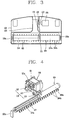
- a suction head for a vacuum cleaner in accordance with a first embodiment of the present invention includes a casing 102 having a suction port 101 for sucking alien substances from the floor in its lower side, a suction nozzle 103 installed inside the casing 102, for collecting the alien substances sucked from the suction port 101, a volume of which being reduced from the suction port 101 to the opposite side, an agitator 104 having a cylindrical agitator body 104a rotatably installed inside the suction port 101, and a plurality of brushes 104b installed on the outside surface of the agitator body 104a, for brushing alien substances from the floor, a driving motor 105 positioned inside the casing 102, for generating a driving force for performing forward/backward reciprocating rotation in a predetermined angle, a driving force transmitting unit 116 for transmitting the driving force of the driving motor 105 to the agitator 104, so that the agitator 104 can perform the reciprocating rotation in a
- the brushes 104b installed in the agitator 104 are evenly arranged in the length direction of the agitator 104.
- the brushes 104b are installed in rows in the length direction of the agitator 104, which is not intended to be limiting. That is, the brushes 104b are formed in at least one row in a rotation angle range of the agitator 104.
- the brushes 104b need not to be installed in the whole circumferential direction of the agitator 140 but limitedly installed in the lower side of the agitator 104 in the length direction, which cuts down manufacturing expenses.
- the driving motor 105 includes a stator 121 having two pairs of stator side teeth 121a protruded from its inside surface in the diagonal direction, and coils 124 wound up on the stator side teeth 121a, a rotor 122 having rotor side teeth 122a protruded from its both ends, and performing reciprocating rotation between the stator side teeth 121a, and a motor shaft 123 inserted into the center of the rotor 122.
- the driving force transmitting unit 116 is comprised of a rotary link 112 fixed to the motor shaft 123 of the driving motor 105, for performing reciprocating rotation coaxially to the motor shaft 123, a hinge bracket 115 fixed to one side of the outer circumference of the agitator 104, and a connecting rod 113 having its one end hinge-connected to the rotary link 112 and its other end hinge-connected to the hinge bracket 115, and performing angular reciprocating motion by the reciprocating rotation of the rotary link 112.
- the resonance unit includes a torsion bar 114 positioned in a hollow unit 114a formed inside the agitator 104 coaxially to a central shaft of the agitator 104, the torsion bar having its one end fixed to the inside of the agitator 104 and its other end fixed to the casing 102 through a spring fixing unit 102a mounted on the inside surface of the casing 102.
- the suction force When power is transmitted to the vacuum cleaner, the suction force is generated in the suction port 101 of the suction head due to the suction force generated in a main body of the vacuum cleaner, and alien substances such as dust are sucked from the floor 125 to the main body through the suction port 101 by the suction force.
- the driving force for performing the reciprocating rotation is generated in the driving motor 105.
- the driving force of the driving motor 105 is transmitted to the agitator 104 through the driving force transmitting unit 116, the agitator 104 performs the reciprocating rotation in a predetermined angle range. Alien substances such as dust are separated from the floor 125 by the brushes 104b formed on the outside surface of the agitator 104 in the length direction, and sucked through the suction port 101.
- the agitator 104 performs the reciprocating rotation at a high speed in the predetermined angle range.
- the brushes 104b brush the floor 125 by the rotation of the agitator 104, to easily suck alien substances from the floor 125.
- the suction head for the vacuum cleaner in accordance with the first embodiment of the present invention prevents thin and long alien substances such as hairs or threads from getting wound or tangled on the agitator, by forming the agitator to perform the reciprocating rotation in the predetermined angle range, and brushes the whole area of the suction head, by evenly installing the brushes on the whole surface of the agitator in the length direction, thereby improving cleaning performance of the vacuum cleaner.
- the suction head for the vacuum cleaner includes the resonance unit for resonating the reciprocating rotation of the driving motor, thereby stably rotating the agitator at a high speed.
- a suction head for a vacuum cleaner in accordance with a second embodiment of the present invention will now be explained with reference to Fig. 6. Same reference numerals are used for the same parts as the first embodiment of the present invention.
- a driving motor 205 in the suction head for the vacuum cleaner, includes a stator 221 having one pair of stator side teeth 221a protruded from its inside surface in the diagonal direction, and coils 224 wound up on the stator side teeth 221a, a rotor 222 having rotor side teeth 222a protruded from its both ends, and performing reciprocating rotation between the stator side teeth 221a, and a motor shaft 223 inserted into the center of the rotor 222.
- a resonance unit for resonating the rotary motion of the driving motor 205 is comprised of a pair of coil springs 214 having their one side ends fixed respectively to both ends of a rotary link 212 whose center is coaxially connected to the motor shaft 223 of the driving motor 205, and their other side ends fixed respectively to the driving motor 205.
- the coil springs 214 can be fixed to the inside surface of the casing 102 as well, and the coil springs 214 are installed in the area where the stator side teeth 221 a of the stator 221 are not formed.
- the rotary link 212 and the agitator 104 are connected through a connecting rod 213 hinge-connected to the hinge bracket 115 installed in one side of the outer circumference of the agitator 104 and the rotary link 212, respectively.
- the rotor 222 When power of Bb pole of the teeth 221 a is intercepted, the rotor 222 is rotated in the clockwise direction by a restitution force of the coil spring 214 installed in the opposite side of the stator side teeth 221 a, the rotary link 212 connected to the motor shaft 223 is rotated in the clockwise direction, and the connecting rod 213 connected to the rotary link 212 moves to rotate the agitator 104 in the clockwise direction.
- the rotation and resonance are repeated at a high speed. Therefore, the agitator 104 performs the reciprocating rotation at a high speed in a predetermined angle range.
- the brushes 104b brush the floor 125 by the rotation of the agitator 104, to easily suck alien substances from the floor 125.
- the suction head for the vacuum cleaner in accordance with the second embodiment of the present invention shows the same operations and effects as the first embodiment described above.
- a suction head for a vacuum cleaner in accordance with a third embodiment of the present invention will now be explained with reference to Fig. 7. Same reference numerals are used for the same parts as the first and second embodiments of the present invention.
- the suction head for the vacuum cleaner in accordance with the third embodiment of the present invention includes a casing 102 having a suction port 101 for sucking alien substances from the floor in its lower side, a suction nozzle 103 installed inside the casing 102, for collecting the alien substances sucked from the suction port 101, a volume of which being reduced from the suction port 101 to the opposite side, an agitator 104 having a cylindrical agitator body 104a rotatably installed inside the suction port 101, and a plurality of brushes 104b installed on the outside surface of the agitator body 104a, for brushing alien substances, a driving motor 305 positioned inside the casing 102, for generating a driving force for performing forward/backward reciprocating rotation in a predetermined angle, and a resonance unit for resonating the reciprocating rotation of the agitator 104.
- the inside components of the driving motor 305 are identical to the first or second embodiment of the present invention.
- the driving motor 305 is installed in one side of the agitator 104 in the length direction so that a motor shaft 323 can be coaxially connected to a central shaft of the agitator 104.
- the resonance unit includes a spiral spring 314 having its one end fixed to the motor shaft 323 and its other end fixed to the outside surface of the driving motor 305.
- the other side of the spiral spring 314 can be fixed to the inside surface of the casing 102 as well as the outside surface of the driving motor 305.
- the agitator 104 fixed to the motor shaft 323 is rotated in the forward/backward direction in a predetermined angle range.
- the rotary motion of the agitator 104 is resonated due to an elastic restitution force of the spiral spring 314. Accordingly, the agitator 104 can be stably rotated at a high speed in the forward/backward direction in the predetermined angle range.
- the suction head for the vacuum cleaner in accordance with the third embodiment of the present invention prevents thin and long alien substances such as hairs or threads from getting wound or tangled on the agitator, by forming the agitator to perform the reciprocating rotation in the predetermined angle range, and brushes the whole area of the suction head, by evenly installing the brushes on the whole surface of the agitator in the length direction, thereby improving cleaning performance of the vacuum cleaner.
- the motor shaft of the driving motor is connected coaxially to the central shaft of the agitator, so that the driving force of the driving motor can be transmitted to the agitator without using a special driving force transmitting unit.
- the whole structure is simplified and manufacturing expenses are cut down.
Landscapes
- Engineering & Computer Science (AREA)
- Mechanical Engineering (AREA)
- Nozzles For Electric Vacuum Cleaners (AREA)
Applications Claiming Priority (2)
| Application Number | Priority Date | Filing Date | Title |
|---|---|---|---|
| KR10-2003-0051095A KR100480145B1 (ko) | 2003-07-24 | 2003-07-24 | 진공청소기의 흡입헤드 |
| KR2003051095 | 2003-07-24 |
Publications (3)
| Publication Number | Publication Date |
|---|---|
| EP1500366A2 true EP1500366A2 (de) | 2005-01-26 |
| EP1500366A3 EP1500366A3 (de) | 2006-06-21 |
| EP1500366B1 EP1500366B1 (de) | 2010-05-26 |
Family
ID=33487941
Family Applications (1)
| Application Number | Title | Priority Date | Filing Date |
|---|---|---|---|
| EP03029749A Expired - Lifetime EP1500366B1 (de) | 2003-07-24 | 2003-12-23 | Saugkopf für Staubsauger |
Country Status (6)
| Country | Link |
|---|---|
| US (1) | US7363682B2 (de) |
| EP (1) | EP1500366B1 (de) |
| JP (1) | JP3990360B2 (de) |
| KR (1) | KR100480145B1 (de) |
| CN (1) | CN100381092C (de) |
| DE (1) | DE60332719D1 (de) |
Cited By (1)
| Publication number | Priority date | Publication date | Assignee | Title |
|---|---|---|---|---|
| US7657967B2 (en) | 2004-12-30 | 2010-02-09 | Lg Electronics Inc. | Brush vibrating apparatus for vacuum cleaner |
Families Citing this family (21)
| Publication number | Priority date | Publication date | Assignee | Title |
|---|---|---|---|---|
| KR100595558B1 (ko) * | 2004-06-12 | 2006-07-03 | 엘지전자 주식회사 | 진공청소기의 흡입헤드 |
| KR100556811B1 (ko) * | 2004-06-12 | 2006-03-10 | 엘지전자 주식회사 | 진공청소기의 흡입헤드 |
| KR100797604B1 (ko) * | 2006-08-28 | 2008-01-23 | 주식회사 퓨어네츄럴컴퍼니 | 청소기용 헤드의 구동 제어방법 및 이를 이용한 청소기용헤드 |
| US9295362B2 (en) | 2008-03-17 | 2016-03-29 | Aktiebolaget Electrolux | Vacuum cleaner agitator cleaner with power control |
| US9820626B2 (en) | 2008-03-17 | 2017-11-21 | Aktiebolaget Electrolux | Actuator mechanism for a brushroll cleaner |
| CN103637747B (zh) * | 2008-03-17 | 2017-04-12 | 伊莱克斯家用产品有限公司 | 具有清洁部件的搅拌器 |
| US10117553B2 (en) | 2008-03-17 | 2018-11-06 | Aktiebolaget Electrolux | Cleaning nozzle for a vacuum cleaner |
| CN103945749B (zh) | 2011-10-26 | 2016-06-01 | 伊莱克斯公司 | 用于真空吸尘器的清洁吸嘴 |
| WO2013113395A1 (en) | 2012-02-02 | 2013-08-08 | Aktiebolaget Electrolux | Cleaning arrangement for a nozzle of a vacuum cleaner |
| EP2653085B1 (de) * | 2012-04-19 | 2018-05-30 | LG Electronics Inc. | Staubsauger und Saugdüse für Staubsauger |
| CN104703526B (zh) | 2012-12-21 | 2018-01-30 | 伊莱克斯公司 | 用于真空吸尘器的可旋转构件的清洁设备、吸尘器吸嘴、真空吸尘器以及清洁单元 |
| US9072416B2 (en) | 2013-03-15 | 2015-07-07 | Aktiebolaget Electrolux | Vacuum cleaner agitator cleaner with brushroll lifting mechanism |
| EP3289946B1 (de) | 2013-05-02 | 2021-03-31 | Aktiebolaget Electrolux | Reinigungsdüse für einen staubsauger |
| KR102386214B1 (ko) | 2015-11-19 | 2022-04-14 | 삼성전자주식회사 | 진공청소기 |
| US11006796B2 (en) | 2016-09-23 | 2021-05-18 | Samsung Electronics Co., Ltd. | Suction nozzle and vacuum cleaner and robot cleaner having the same |
| CN107518835B (zh) * | 2017-09-06 | 2021-02-02 | 九阳股份有限公司 | 一种清洁机器人 |
| DE102018207213B4 (de) * | 2018-05-09 | 2023-07-06 | Vorwerk & Co. Interholding Gmbh | Vorsatzgerät mit Reinigungswalze für Staubsauger |
| US12239267B2 (en) | 2019-07-02 | 2025-03-04 | Mark Jeffery Giarritta | Four-direction scrubbing carpet shampooer |
| USD1102071S1 (en) * | 2023-12-07 | 2025-11-11 | Emerson Electric Co. | Vacuum cleaner floor tool |
| USD1102070S1 (en) * | 2023-12-07 | 2025-11-11 | Emerson Electric Co. | Vacuum cleaner floor tool |
| USD1104385S1 (en) * | 2023-12-07 | 2025-12-02 | Emerson Electric Co. | Vacuum cleaner floor tool |
Family Cites Families (22)
| Publication number | Priority date | Publication date | Assignee | Title |
|---|---|---|---|---|
| US1197915A (en) * | 1915-08-14 | 1916-09-12 | Clifford C Dance | Vacuum-cleaner. |
| US1820350A (en) * | 1923-03-24 | 1931-08-25 | Dance Suction Sweeper Company | Vacuum cleaner |
| US1689811A (en) * | 1926-07-12 | 1928-10-30 | Witt Milton | Vacuum cleaner |
| US1805203A (en) * | 1929-06-21 | 1931-05-12 | Julius B Lewis | Vacuum sweeper |
| US2635278A (en) * | 1951-08-18 | 1953-04-21 | William J Belknap | Floor drying apparatus containing baffle structure for separation of entrained liquid |
| US3483410A (en) * | 1967-11-21 | 1969-12-09 | Beckman Instruments Inc | High torque motor |
| SE387836B (sv) * | 1974-12-19 | 1976-09-20 | Electrolux Ab | Dammsugarmunstycke |
| US4136420A (en) * | 1977-04-15 | 1979-01-30 | Chemko Industries, Inc. | Carpet soil extracting wand having a powered brush |
| US4156952A (en) * | 1977-10-04 | 1979-06-05 | Chemko Industries, Inc. | Carpet soil extractor having a powered brush |
| US4272861A (en) * | 1979-09-28 | 1981-06-16 | Wetrok, Inc. | Carpet cleaning device |
| US4430768A (en) * | 1982-03-24 | 1984-02-14 | Novinger Harry E | Agitator structure for suction cleaners |
| JPS63264030A (ja) | 1987-04-23 | 1988-10-31 | 東芝テック株式会社 | 電気掃除機の吸込口体 |
| CN2072823U (zh) * | 1990-09-29 | 1991-03-13 | 常玉国 | 振动式吸尘器头 |
| CN2092296U (zh) * | 1991-02-26 | 1992-01-08 | 徐扬 | 高效自动吸尘器 |
| JPH07313411A (ja) | 1994-05-30 | 1995-12-05 | Sharp Corp | 電気掃除機の吸い込み装置 |
| WO1995033419A1 (en) * | 1994-06-06 | 1995-12-14 | Teledyne Water Pik Division Of Teledyne Industries, Inc. | High frequency electric toothbrush |
| CN2230570Y (zh) | 1995-02-21 | 1996-07-10 | 张殿刚 | 一种除尘器 |
| CA2192882C (en) * | 1996-01-23 | 2002-04-16 | Shigenori Hato | Suction tool for an electric vacuum cleaner |
| DE19602452A1 (de) | 1996-01-24 | 1997-08-07 | Zettl Gmbh & Co F | Verfahren zum Granulieren von Schlämmen |
| US5890249A (en) * | 1997-05-20 | 1999-04-06 | Hoffman; Gary P. | Multi-purpose vibration cleaning device |
| US6148475A (en) * | 1999-06-08 | 2000-11-21 | The Scott Fetzer Company | Vacuum cleaner with vibrating brushes |
| KR100438607B1 (ko) * | 2001-08-27 | 2004-07-02 | 엘지전자 주식회사 | 파워브러쉬를 구비한 진공청소기의 흡입헤드 |
-
2003
- 2003-07-24 KR KR10-2003-0051095A patent/KR100480145B1/ko not_active Expired - Fee Related
- 2003-12-23 EP EP03029749A patent/EP1500366B1/de not_active Expired - Lifetime
- 2003-12-23 DE DE60332719T patent/DE60332719D1/de not_active Expired - Lifetime
- 2003-12-31 US US10/748,297 patent/US7363682B2/en not_active Expired - Fee Related
-
2004
- 2004-01-15 JP JP2004008300A patent/JP3990360B2/ja not_active Expired - Fee Related
- 2004-02-02 CN CNB2004100032032A patent/CN100381092C/zh not_active Expired - Fee Related
Cited By (1)
| Publication number | Priority date | Publication date | Assignee | Title |
|---|---|---|---|---|
| US7657967B2 (en) | 2004-12-30 | 2010-02-09 | Lg Electronics Inc. | Brush vibrating apparatus for vacuum cleaner |
Also Published As
| Publication number | Publication date |
|---|---|
| EP1500366B1 (de) | 2010-05-26 |
| CN1575733A (zh) | 2005-02-09 |
| JP3990360B2 (ja) | 2007-10-10 |
| DE60332719D1 (de) | 2010-07-08 |
| CN100381092C (zh) | 2008-04-16 |
| KR100480145B1 (ko) | 2005-04-06 |
| JP2005040575A (ja) | 2005-02-17 |
| KR20050012012A (ko) | 2005-01-31 |
| US20050015922A1 (en) | 2005-01-27 |
| US7363682B2 (en) | 2008-04-29 |
| EP1500366A3 (de) | 2006-06-21 |
Similar Documents
| Publication | Publication Date | Title |
|---|---|---|
| US7363682B2 (en) | Suction head for vacuum cleaner | |
| EP1604603B1 (de) | Saugkopf für Staubsauger | |
| JP2002085301A (ja) | 真空掃除機用パワーブラシアセンブリ | |
| US6785933B2 (en) | Suction head of vacuum cleaner with power brush | |
| KR100638205B1 (ko) | 진공 청소기 | |
| CN104274126B (zh) | 电吸尘器的吸入部件和具有它的电吸尘器 | |
| KR100429991B1 (ko) | 파워브러쉬를 구비한 진공청소기의 흡입헤드 | |
| JPH07322A (ja) | 掃除機用吸入ノズル | |
| CN102258351B (zh) | 电动吸尘器 | |
| EP1700556B1 (de) | System und Verfahren zur Erhöhung der Trägheit in einer Turbinenbürste | |
| EP1495707B1 (de) | Staubsaugerkopf fuer Staubsauger | |
| GB2401309A (en) | Suction cleaner with improved suction head air flow | |
| US20050273970A1 (en) | Suction head of vacuum cleaner | |
| CN114271731A (zh) | 清洁头及清洁设备 | |
| WO2024139680A1 (zh) | 电机以及电动牙刷 | |
| CN110840322A (zh) | 吸尘器和地刷装置 | |
| KR100550555B1 (ko) | 청소기의 흡입기구 | |
| KR100495060B1 (ko) | 청소기의 흡입기구 | |
| JPH06142018A (ja) | 掃除機用吸入ノズルの回転ロータ | |
| CN223944358U (zh) | 清洁头及表面清洁设备 | |
| KR20120002878A (ko) | 진공청소기용 브러쉬 모터 | |
| CN121154037A (zh) | 吸入口部、吸入口体以及电动吸尘器 | |
| WO2024139681A1 (zh) | 弹性件以及共振组件 | |
| KR100606134B1 (ko) | 회전공진형 모터의 전원공급장치 | |
| JPH119522A (ja) | 掃除機用床ノズル |
Legal Events
| Date | Code | Title | Description |
|---|---|---|---|
| PUAI | Public reference made under article 153(3) epc to a published international application that has entered the european phase |
Free format text: ORIGINAL CODE: 0009012 |
|
| 17P | Request for examination filed |
Effective date: 20040110 |
|
| AK | Designated contracting states |
Kind code of ref document: A2 Designated state(s): AT BE BG CH CY CZ DE DK EE ES FI FR GB GR HU IE IT LI LU MC NL PT RO SE SI SK TR |
|
| AX | Request for extension of the european patent |
Extension state: AL LT LV MK |
|
| PUAL | Search report despatched |
Free format text: ORIGINAL CODE: 0009013 |
|
| AK | Designated contracting states |
Kind code of ref document: A3 Designated state(s): AT BE BG CH CY CZ DE DK EE ES FI FR GB GR HU IE IT LI LU MC NL PT RO SE SI SK TR |
|
| AX | Request for extension of the european patent |
Extension state: AL LT LV MK |
|
| 17Q | First examination report despatched |
Effective date: 20061130 |
|
| AKX | Designation fees paid |
Designated state(s): DE FR GB IT |
|
| GRAP | Despatch of communication of intention to grant a patent |
Free format text: ORIGINAL CODE: EPIDOSNIGR1 |
|
| GRAS | Grant fee paid |
Free format text: ORIGINAL CODE: EPIDOSNIGR3 |
|
| GRAA | (expected) grant |
Free format text: ORIGINAL CODE: 0009210 |
|
| AK | Designated contracting states |
Kind code of ref document: B1 Designated state(s): DE FR GB IT |
|
| REG | Reference to a national code |
Ref country code: GB Ref legal event code: FG4D |
|
| REF | Corresponds to: |
Ref document number: 60332719 Country of ref document: DE Date of ref document: 20100708 Kind code of ref document: P |
|
| PLBE | No opposition filed within time limit |
Free format text: ORIGINAL CODE: 0009261 |
|
| STAA | Information on the status of an ep patent application or granted ep patent |
Free format text: STATUS: NO OPPOSITION FILED WITHIN TIME LIMIT |
|
| 26N | No opposition filed |
Effective date: 20110301 |
|
| REG | Reference to a national code |
Ref country code: DE Ref legal event code: R097 Ref document number: 60332719 Country of ref document: DE Effective date: 20110228 |
|
| REG | Reference to a national code |
Ref country code: FR Ref legal event code: ST Effective date: 20110831 |
|
| PG25 | Lapsed in a contracting state [announced via postgrant information from national office to epo] |
Ref country code: FR Free format text: LAPSE BECAUSE OF NON-PAYMENT OF DUE FEES Effective date: 20110103 |
|
| PGFP | Annual fee paid to national office [announced via postgrant information from national office to epo] |
Ref country code: GB Payment date: 20161110 Year of fee payment: 14 Ref country code: DE Payment date: 20161107 Year of fee payment: 14 |
|
| PGFP | Annual fee paid to national office [announced via postgrant information from national office to epo] |
Ref country code: IT Payment date: 20161214 Year of fee payment: 14 |
|
| REG | Reference to a national code |
Ref country code: DE Ref legal event code: R119 Ref document number: 60332719 Country of ref document: DE |
|
| GBPC | Gb: european patent ceased through non-payment of renewal fee |
Effective date: 20171223 |
|
| PG25 | Lapsed in a contracting state [announced via postgrant information from national office to epo] |
Ref country code: IT Free format text: LAPSE BECAUSE OF NON-PAYMENT OF DUE FEES Effective date: 20171223 Ref country code: DE Free format text: LAPSE BECAUSE OF NON-PAYMENT OF DUE FEES Effective date: 20180703 |
|
| PG25 | Lapsed in a contracting state [announced via postgrant information from national office to epo] |
Ref country code: GB Free format text: LAPSE BECAUSE OF NON-PAYMENT OF DUE FEES Effective date: 20171223 |