EP1502845B1 - Véhicule d'enfant - Google Patents
Véhicule d'enfant Download PDFInfo
- Publication number
- EP1502845B1 EP1502845B1 EP04016281A EP04016281A EP1502845B1 EP 1502845 B1 EP1502845 B1 EP 1502845B1 EP 04016281 A EP04016281 A EP 04016281A EP 04016281 A EP04016281 A EP 04016281A EP 1502845 B1 EP1502845 B1 EP 1502845B1
- Authority
- EP
- European Patent Office
- Prior art keywords
- child
- adapter
- coupling element
- pedal car
- bracket
- Prior art date
- Legal status (The legal status is an assumption and is not a legal conclusion. Google has not performed a legal analysis and makes no representation as to the accuracy of the status listed.)
- Expired - Lifetime
Links
Images





Classifications
-
- B—PERFORMING OPERATIONS; TRANSPORTING
- B62—LAND VEHICLES FOR TRAVELLING OTHERWISE THAN ON RAILS
- B62K—CYCLES; CYCLE FRAMES; CYCLE STEERING DEVICES; RIDER-OPERATED TERMINAL CONTROLS SPECIALLY ADAPTED FOR CYCLES; CYCLE AXLE SUSPENSIONS; CYCLE SIDECARS, FORECARS, OR THE LIKE
- B62K9/00—Children's cycles
Definitions
- the invention relates to a child pedal vehicle according to the preamble of patent claim 1.
- Such toy vehicles have an additional play value for children when equipped with accessories that allow additional tasks or "work” to be carried out in a playful manner beyond actual driving with the pedal vehicle.
- An example of this is a child pedal vehicle with a loading shovel held on two arms, which can be loaded, for example, with sand in a lowered position, to be subsequently pivoted upwards and locked in the raised position, so that the pedal vehicle now with the load to his Destination can be driven, where by means of a tilting mechanism, the loading bucket pivots and the sand charge can be distributed.
- U.S. Patent 2,816,772 discloses a child pedal vehicle with a snow blade according to the preamble of claim 1.
- Aus US-A-2,776,767 Furthermore, a child pedal vehicle is known, which has a vertically movable held snow blade.
- the present invention has for its object to provide a child pedal vehicle whose game value is increased by the fact that it can be used for new purposes.
- the invention provides that the child pedal vehicle is connected by means of an adapter device with a snow blade.
- the adapter device is releasably connected to the child pedal vehicle, so that the snow blade can be easily attached to the child pedal vehicle and removed again when needed.
- snow blade here refers to the preferred use for clearing snow, of course, should not be ruled out that with the dozer blade other materials lying in the way can be cleared to the side.
- the invention provides that the snow blade can be fixed in different angular positions to the longitudinal direction of the child trolley on the adapter device. Three positions are preferred here, namely a central position running perpendicular to the longitudinal axis of the child trolley and an inclination to the left and to the right.
- the adjustability of the angular position allows the snow to move in different directions and makes the pedal car even more interesting for children.
- the invention provides that the snow blade is held vertically movable. This prevents the snow blade when driving forward of the child trolley by bumps on the ground, for example, protruding Stones or ice is blocked so that the vehicle can not continue. The possible lifting of the snow blade makes such obstacles effective.
- a coupling device for example, consists of two spaced superposed, substantially plate-shaped coupling parts between which an adapter with a total plate-shaped portion engages so that this portion of the adapter without vertical game is recorded.
- a coupling pin Through the two coupling parts and the interposed portion of the adapter lead aligned through holes through which a coupling pin can be inserted, so that the adapter is attached to the child trolley.
- he is with his child pedal vehicle facing end side on the front of the child pedal vehicle, so that it is fixed completely immovable.
- plate-shaped used above is not to be understood that this must be massive plates, but the components produced by plastic injection molding are preferably integrally formed from many wall and strut sections with intermediate cavities.
- the adapter has two laterally spaced guide means for a preferably made of metal bracket, which is connected to a coupling element for a blade holder attached to the shield adapter, wherein the bracket in the guide means over a predetermined range can be raised vertically and in a raised position is pivotable so that the bracket is fixed in this position.
- the bracket has in a front view expediently an inverted U-shape, wherein the coupling element is attached to the lower in the mounting position free ends of the bracket.
- the two parallel spars of the bracket have a rectilinear upper portion and an angled lower portion, and that the spars above and below the kink each have an inwardly projecting pin, which engage in the guide means.
- the guide means are rails externally formed on two laterally spaced, upright portions of the adapter or side grooves in those portions.
- the guide rails or grooves each have a long, substantially vertical guide track, which merges arcuately at the upper end in a short, substantially vertically downwardly facing guideway.
- the metal bracket, on the coupling element, the snow blade is attached to the two pins of the two parallel spars in the working position of the snow blade in both vertical rails or grooves out, in this position, the upper portions of the two parallel spars forward are inclined and the lower, forward angled portions of the spars rest on the corresponding angled tops of two lateral extensions of the adapter.
- the end portions of the lower spar sections are again angled upwards, so that they are aligned horizontally in the working position of the snow blade together with the pushed onto these ends coupling element.
- the snow blade is thus vertically movable by the pins of the bracket in the vertical rails or grooves are movable upwards until these rails or grooves over a predetermined distance arcuate into a downwardly directed blind hole. If the child wants to put the snow plow in a raised rest position, it takes the horizontally extending upper cross member of the bracket and lifts on this handle the bracket with the snow blade first up to the top arcuate transition of the guide rail and pivots the bracket so back that the upper pins enter the two blind holes. In this position, the snow blade is automatically blocked.
- the coupling element which is attached to the two horizontal ends of the parallel spars of the bracket by means of correspondingly shaped lateral projections, contains two holes spaced in the longitudinal direction of the vehicle, while the attached to the back of Schneehoffmschildes, for example, bolted plate adapter to the Schneehoffmschild lying hole and lying to the coupling element preferably has three further holes which lie on a circular arc whose radius coincides with the distance between the two holes of the coupling element.
- the shield adapter preferably contains at a distance parallel superimposed portions between which engages the coupling element without vertical play. In the attachment position, the hole of the coupling element facing the snow blade is aligned with the holes of the shield adapter arranged above and below it.
- a coupling pin is inserted, which forms the axis of rotation for three possible angular positions of the snow blade.
- These three angular positions are adjustable by aligning a selected hole of the shield adapter with the second hole of the coupling element. The selected angular position is fixed by another coupling pin.
- the snow blade is expediently provided on its lower edge with a metal strip in order to avoid or reduce wear of the expediently made of plastic snow blade. According to the invention it is further provided that at least the rear wheels of the child trolley are provided with snow chains.
- the snow blade is attached to a child pedal vehicle having two laterally spaced, liftable ones Has arms to which as an accessory and a loading shovel can be attached.
- the invention provides that an adapter provided with a coupling element can be attached to the two arms, which is to be provided via the coupling element and the above-described blade adapter with the snow blade.
- the lifting of the snow blade is done in this embodiment by pivoting the two arms of the child trolley.
- FIG. 1 shows, purely schematically, a coupling 1 of a child pedal vehicle, which, for example, has the shape of a tractor.
- the preferably mounted on the front of the pedal vehicle clutch (but may also be provided at the rear) includes two spaced superposed coupling parts 2,3, which have such a distance from each other that a transverse wall portion 4 of a generally designated by the reference numeral 5, made of plastic adapter 5 fits substantially without vertical clearance between the coupling parts 2.3.
- the adapter 5 is applied to the front of the child trolley, not shown, aligned through holes 6.7 of the coupling 1 with a through hole 8 through the wall portion 4, so that a coupling pin 9 can be inserted through the three holes to the adapter 5 immovably on the Childrens vehicle to fix.
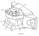
- the adapter 5 has two laterally spaced, upwardly projecting arms 9,10, on the outer sides of guide rails 1 are formed.
- the guide rails 11, which are formed identically on the two arms 9, 10, have a long vertical section 12, which at the upper end arcuate transition into a short, downwardly extending blind hole 13.
- the blind hole 13 goes through to the top 14 to allow the insertion of guide pins 15, 16 of a metal bracket 17.
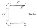
- the bracket 17 has in an end view (Figure 3A) an inverted U-shape with an upper transverse rail 18 in the installation position and two parallel side rails 19.
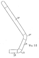
- the side rails 19 have in the side view ( Figure 3B) in the installed position an obliquely forwardly extending portion 20, at a kink 21 in a turn obliquely forward angled portion 22 passes, which merges at a further kink point 23 in a horizontal position in the installed end portion 24.
- the bracket 17 engages with a pin 15 of the portion 20 and a pin 16 of the portion 22 in the lowered working position of the snow blade 25 in the long vertical portion 12 of the guide rail or a guide groove.
- the bracket 17 is lifted and pivoted backwards so that the two pins 15 enter the associated blind holes 13. From this position they can be released only by raising and pivoting the bracket 17 again.
- the adapter 5 has two lateral lugs 26 with a bearing surface 27 for the associated portion 22 of the bracket 17 whose inclination coincides.
- a coupling element 28 is plugged by the two ends 24 are inserted into tubular recesses lateral projections 29 of the coupling element 28 and screwed therein, for example.
- the coupling element 28 has a hole 30 serving as an axis of rotation in the angular adjustment of the snow blade 25 and a second hole 31 spaced therefrom in the longitudinal direction of the child pedal vehicle.
- the height of the coupling piece 28 substantially coincides with the clearance between two projections 32 and 33 of a shield adapter 34.
- the shield adapter 34 is attached to the back of the Schneehoffmschildes 25, preferably screwed.
- FIG. 6 shows, largely schematically, the front end section of two arms 40, which are fastened to a child pedal vehicle, not shown, which can be raised and lowered by means of a mechanism (not shown).
- the two arms 40 are connected to each other by means of a molding 41 which contains recesses 42, in the protruding webs 43 of an adapter 44 are used bar.
- Bolts 45 are guided through aligned holes 46 and 47 in the recesses 42 bounding walls or the webs 43, whereby the adapter 44 is fixedly attached to the two arms 40 of the child trolley.
Landscapes
- Engineering & Computer Science (AREA)
- Mechanical Engineering (AREA)
- Preparation Of Compounds By Using Micro-Organisms (AREA)
- Auxiliary Drives, Propulsion Controls, And Safety Devices (AREA)
- Motorcycle And Bicycle Frame (AREA)
- Handcart (AREA)
- Table Equipment (AREA)
- Body Structure For Vehicles (AREA)
- Pharmaceuticals Containing Other Organic And Inorganic Compounds (AREA)
- Transition And Organic Metals Composition Catalysts For Addition Polymerization (AREA)
- Vehicle Step Arrangements And Article Storage (AREA)
- Braking Elements And Transmission Devices (AREA)
- Acyclic And Carbocyclic Compounds In Medicinal Compositions (AREA)
- Compounds Of Unknown Constitution (AREA)
- Toys (AREA)
- Non-Portable Lighting Devices Or Systems Thereof (AREA)
- Lighting Device Outwards From Vehicle And Optical Signal (AREA)
- Vehicle Interior And Exterior Ornaments, Soundproofing, And Insulation (AREA)
- Carriages For Children, Sleds, And Other Hand-Operated Vehicles (AREA)
Claims (8)
- Véhicule à pédales pour enfant, comportant une lame de déneigement (25), qui est apte à être assemblée au véhicule à pédales par l'intermédiaire d'un dispositif d'adaptation (5, 44) et qui peut être immobilisée dans différentes positions angulaires par rapport au sens longitudinal du véhicule à pédales, caractérisé en ce que la lame de déneigement (25) peut être maintenue mobile dans le sens vertical.
- Véhicule à pédales pour enfant selon la revendication 1, le véhicule à pédales étant muni d'un dispositif d'accouplement, caractérisé en ce qu'un adaptateur (5) peut être fixé contre le dispositif d'accouplement (1), qui comporte deux dispositifs de guidage (11), écartés latéralement l'un de l'autre et destinés à un arceau (17) qui est assemblé à un élément d'accouplement (28) pour un adaptateur (34) fixé contre la lame de déneigement (25), l'arceau (17) étant apte à être relevé verticalement sur une zone déterminée dans le dispositif de guidage (11) et étant apte à pivoter vers une position haute de telle sorte que l'arceau (17) est immobilisé dans cette position.
- Véhicule à pédales pour enfant selon la revendication 2, caractérisé en ce que l'arceau (17), sur une vue de face, a la forme d'un U renversé et en ce que l'élément d'accouplement (28) est enfiché sur les extrémités libres (24) de l'arceau (17).
- Véhicule à pédales pour enfant selon la revendication 2 ou 3, caractérisé en ce que les deux barres longitudinales (19) parallèles de l'arceau (17) comportent une partie supérieure (20) droite et une partie inférieure (22) coudée à partir de celle-ci, et en ce que les barres longitudinales (19) comportent chacune, au-dessus et au-dessous de la zone coudée (21), respectivement un téton (15, 16) en saillie vers l'intérieur, lesquels s'engagent dans le dispositif de guidage (11).
- Véhicule à pédales pour enfant selon l'une quelconque des revendications 2 à 4, caractérisé en ce que les dispositifs de guidage (11) comportent chacun une longue voie de guidage (12) verticale qui, au niveau de l'extrémité supérieure, est prolongée par une courbe qui débouche dans une courte voie de guidage (13) sensiblement verticale orientée vers le bas.
- Véhicule à pédales pour enfant selon l'une quelconque des revendications 2 à 5, caractérisé en ce que l'élément d'accouplement (28) comporte deux forures (30, 31) écartées l'une de l'autre dans le sens longitudinal du véhicule à pédales, et en ce que l'adaptateur (34) de la lame de déneigement comporte une forure (35) située sur le côté de la lame de déneigement (25) et, de préférence, trois autres forures (36, 37, 38) qui sont situées sur un arc de cercle, dont le rayon coïncide avec la distance entre les deux forures (30, 31) de l'élément d'accouplement (28).
- Véhicule à pédales pour enfant selon l'une quelconque des revendications 2 à 6, caractérisé en ce que l'adaptateur (34) de la lame de déneigement comporte deux parties (32, 33) superposées, entre lesquelles l'élément d'accouplement (28) est monté sensiblement sans jeu vertical.
- Véhicule à pédales pour enfant selon la revendication 1, le véhicule à pédales comportant deux bras relevables et abaissables, écartés latéralement l'un de l'autre, caractérisé en ce qu'un adaptateur (44), muni d'un élément d'accouplement (48), est apte à être monté contre les deux bras, et en ce que l'élément d'accouplement (48) est apte à être couplé à un adaptateur (34) fixé contre la lame de déneigement (25) .
Priority Applications (1)
| Application Number | Priority Date | Filing Date | Title |
|---|---|---|---|
| PL04016281T PL1502845T3 (pl) | 2003-07-30 | 2004-07-10 | Pojazd dla dzieci |
Applications Claiming Priority (2)
| Application Number | Priority Date | Filing Date | Title |
|---|---|---|---|
| DE10334749A DE10334749B4 (de) | 2003-07-30 | 2003-07-30 | Kindertretfahrzeug |
| DE10334749 | 2003-07-30 |
Publications (3)
| Publication Number | Publication Date |
|---|---|
| EP1502845A2 EP1502845A2 (fr) | 2005-02-02 |
| EP1502845A3 EP1502845A3 (fr) | 2006-04-12 |
| EP1502845B1 true EP1502845B1 (fr) | 2007-09-12 |
Family
ID=33521482
Family Applications (1)
| Application Number | Title | Priority Date | Filing Date |
|---|---|---|---|
| EP04016281A Expired - Lifetime EP1502845B1 (fr) | 2003-07-30 | 2004-07-10 | Véhicule d'enfant |
Country Status (7)
| Country | Link |
|---|---|
| EP (1) | EP1502845B1 (fr) |
| AT (1) | ATE372919T1 (fr) |
| DE (2) | DE10334749B4 (fr) |
| DK (1) | DK1502845T3 (fr) |
| ES (1) | ES2294403T3 (fr) |
| NO (1) | NO324186B1 (fr) |
| PL (1) | PL1502845T3 (fr) |
Family Cites Families (8)
| Publication number | Priority date | Publication date | Assignee | Title |
|---|---|---|---|---|
| US2455692A (en) * | 1947-03-27 | 1948-12-07 | Frederick A Mcdunnah | Velocipede toy shovel attachment |
| US2776767A (en) * | 1954-01-28 | 1957-01-08 | Verne H Stover | Dozer and loading attachment for tricycles |
| US2816772A (en) * | 1955-06-07 | 1957-12-17 | Lapointe Alfred | Child's wagon with obstacle clearing guard |
| DE1975663U (de) * | 1967-08-08 | 1967-12-21 | Karlmann Kutschka Spielwarenfa | Spielfahrzeug. |
| DE2000038A1 (de) * | 1970-01-02 | 1971-07-08 | Basf Ag | Verfahren zum Faerben von Celluloseestern |
| DE8901489U1 (de) * | 1989-02-09 | 1989-04-06 | BIG-Spielwarenfabrik Dipl.-Ing. Ernst A. Bettag, 8510 Fürth | Fahrbares Kinderspielzeug |
| DE19600440C1 (de) * | 1996-01-09 | 1997-04-03 | Schneider Gmbh & Co Kg Franz | Kinderspielzeug |
| DE20000385U1 (de) * | 2000-01-11 | 2001-06-07 | Preis, Erwin, 88178 Heimenkirch | Schneepflug für Kindertretmobile u.dgl. |
-
2003
- 2003-07-30 DE DE10334749A patent/DE10334749B4/de not_active Expired - Lifetime
-
2004
- 2004-07-10 ES ES04016281T patent/ES2294403T3/es not_active Expired - Lifetime
- 2004-07-10 DE DE502004004925T patent/DE502004004925D1/de not_active Expired - Lifetime
- 2004-07-10 PL PL04016281T patent/PL1502845T3/pl unknown
- 2004-07-10 DK DK04016281T patent/DK1502845T3/da active
- 2004-07-10 AT AT04016281T patent/ATE372919T1/de active
- 2004-07-10 EP EP04016281A patent/EP1502845B1/fr not_active Expired - Lifetime
- 2004-07-27 NO NO20043194A patent/NO324186B1/no unknown
Also Published As
| Publication number | Publication date |
|---|---|
| DE10334749B4 (de) | 2007-01-25 |
| DE502004004925D1 (de) | 2007-10-25 |
| NO20043194L (no) | 2005-01-31 |
| NO324186B1 (no) | 2007-09-03 |
| DE10334749A1 (de) | 2005-02-24 |
| ES2294403T3 (es) | 2008-04-01 |
| EP1502845A3 (fr) | 2006-04-12 |
| EP1502845A2 (fr) | 2005-02-02 |
| DK1502845T3 (da) | 2008-01-21 |
| PL1502845T3 (pl) | 2008-04-30 |
| ATE372919T1 (de) | 2007-09-15 |
Similar Documents
| Publication | Publication Date | Title |
|---|---|---|
| DE60211493T2 (de) | Rollbare gehhilfe mit einer vorrichtung zur erleichterung des fahrens | |
| EP0518168B1 (fr) | Dispositif de direction d'un véhicule, en particulier tracteur de jardin ou tondeuse de gazon | |
| EP1925754B1 (fr) | Excavatrice combinée route-rail | |
| EP1632275B1 (fr) | Véhicule jouet | |
| DE102009007134B4 (de) | Anhänger für ein Kinderfahrzeug | |
| DE10334749B4 (de) | Kindertretfahrzeug | |
| EP2106933B1 (fr) | Agencement d'application réglable en hauteur d'un embrayage de remorque sur un véhicule de traction | |
| DE20313069U1 (de) | Kindertretfahrzeug | |
| DE2322504B2 (de) | Fahrzeug mit knicklenkung | |
| DE3914423C2 (de) | Zubehör für Anbaugeräte | |
| EP1362772A1 (fr) | Véhicule pour retourner un silo de compost | |
| EP0783906B1 (fr) | Jouet pour enfants | |
| DE8903451U1 (de) | Mit entsprechenden Wagen schachtelbarer Schubgepäckwagen | |
| DE29715943U1 (de) | Kunststoff-Kinderauto und Kinderfahrmobil | |
| DE102004057578B3 (de) | Schlitten mit mindestens drei Kufen | |
| DE8133936U1 (de) | "skibob" | |
| AT390814B (de) | Vorrichtung zum raeumen von schnee | |
| EP2481455B1 (fr) | Véhicule de jeu | |
| DE1986932U (de) | Motorfahrzeug, insbesondere Ackerschlepper, mit Uberschlagschutzbugel | |
| DE8516572U1 (de) | Zusammenklappbarer Rodelschlitten | |
| EP2441601A1 (fr) | Disque rotatif d'un passage entre deux éléments de véhicules reliés de manière articulée | |
| DE7013285U (de) | Frontlader. | |
| EP1086877A2 (fr) | Véhicule pour le transport de personnes en particulier | |
| DE1555448A1 (de) | Auffahrvorrichtung fuer selbstfahrende Radfahrzeuge | |
| DE2946309A1 (de) | Traktor mit kabine |
Legal Events
| Date | Code | Title | Description |
|---|---|---|---|
| PUAI | Public reference made under article 153(3) epc to a published international application that has entered the european phase |
Free format text: ORIGINAL CODE: 0009012 |
|
| AK | Designated contracting states |
Kind code of ref document: A2 Designated state(s): AT BE BG CH CY CZ DE DK EE ES FI FR GB GR HU IE IT LI LU MC NL PL PT RO SE SI SK TR |
|
| AX | Request for extension of the european patent |
Extension state: AL HR LT LV MK |
|
| PUAL | Search report despatched |
Free format text: ORIGINAL CODE: 0009013 |
|
| AK | Designated contracting states |
Kind code of ref document: A3 Designated state(s): AT BE BG CH CY CZ DE DK EE ES FI FR GB GR HU IE IT LI LU MC NL PL PT RO SE SI SK TR |
|
| AX | Request for extension of the european patent |
Extension state: AL HR LT LV MK |
|
| 17P | Request for examination filed |
Effective date: 20061006 |
|
| 17Q | First examination report despatched |
Effective date: 20061107 |
|
| AKX | Designation fees paid |
Designated state(s): AT BE BG CH CY CZ DE DK EE ES FI FR GB GR HU IE IT LI LU MC NL PL PT RO SE SI SK TR |
|
| GRAP | Despatch of communication of intention to grant a patent |
Free format text: ORIGINAL CODE: EPIDOSNIGR1 |
|
| GRAS | Grant fee paid |
Free format text: ORIGINAL CODE: EPIDOSNIGR3 |
|
| GRAA | (expected) grant |
Free format text: ORIGINAL CODE: 0009210 |
|
| AK | Designated contracting states |
Kind code of ref document: B1 Designated state(s): AT BE BG CH CY CZ DE DK EE ES FI FR GB GR HU IE IT LI LU MC NL PL PT RO SE SI SK TR |
|
| REG | Reference to a national code |
Ref country code: GB Ref legal event code: FG4D Free format text: NOT ENGLISH |
|
| REG | Reference to a national code |
Ref country code: CH Ref legal event code: EP |
|
| REF | Corresponds to: |
Ref document number: 502004004925 Country of ref document: DE Date of ref document: 20071025 Kind code of ref document: P |
|
| REG | Reference to a national code |
Ref country code: IE Ref legal event code: FG4D Free format text: LANGUAGE OF EP DOCUMENT: GERMAN |
|
| GBT | Gb: translation of ep patent filed (gb section 77(6)(a)/1977) |
Effective date: 20071121 |
|
| REG | Reference to a national code |
Ref country code: SE Ref legal event code: TRGR |
|
| REG | Reference to a national code |
Ref country code: CH Ref legal event code: NV Representative=s name: KIRKER & CIE S.A. |
|
| REG | Reference to a national code |
Ref country code: DK Ref legal event code: T3 |
|
| NLV1 | Nl: lapsed or annulled due to failure to fulfill the requirements of art. 29p and 29m of the patents act | ||
| REG | Reference to a national code |
Ref country code: ES Ref legal event code: FG2A Ref document number: 2294403 Country of ref document: ES Kind code of ref document: T3 |
|
| PG25 | Lapsed in a contracting state [announced via postgrant information from national office to epo] |
Ref country code: GR Free format text: LAPSE BECAUSE OF FAILURE TO SUBMIT A TRANSLATION OF THE DESCRIPTION OR TO PAY THE FEE WITHIN THE PRESCRIBED TIME-LIMIT Effective date: 20071213 Ref country code: NL Free format text: LAPSE BECAUSE OF FAILURE TO SUBMIT A TRANSLATION OF THE DESCRIPTION OR TO PAY THE FEE WITHIN THE PRESCRIBED TIME-LIMIT Effective date: 20070912 |
|
| REG | Reference to a national code |
Ref country code: IE Ref legal event code: FD4D Ref country code: PL Ref legal event code: T3 |
|
| ET | Fr: translation filed | ||
| PG25 | Lapsed in a contracting state [announced via postgrant information from national office to epo] |
Ref country code: PT Free format text: LAPSE BECAUSE OF FAILURE TO SUBMIT A TRANSLATION OF THE DESCRIPTION OR TO PAY THE FEE WITHIN THE PRESCRIBED TIME-LIMIT Effective date: 20080212 Ref country code: SK Free format text: LAPSE BECAUSE OF FAILURE TO SUBMIT A TRANSLATION OF THE DESCRIPTION OR TO PAY THE FEE WITHIN THE PRESCRIBED TIME-LIMIT Effective date: 20070912 |
|
| PG25 | Lapsed in a contracting state [announced via postgrant information from national office to epo] |
Ref country code: RO Free format text: LAPSE BECAUSE OF FAILURE TO SUBMIT A TRANSLATION OF THE DESCRIPTION OR TO PAY THE FEE WITHIN THE PRESCRIBED TIME-LIMIT Effective date: 20070912 |
|
| PLBE | No opposition filed within time limit |
Free format text: ORIGINAL CODE: 0009261 |
|
| STAA | Information on the status of an ep patent application or granted ep patent |
Free format text: STATUS: NO OPPOSITION FILED WITHIN TIME LIMIT |
|
| 26N | No opposition filed |
Effective date: 20080613 |
|
| PG25 | Lapsed in a contracting state [announced via postgrant information from national office to epo] |
Ref country code: IE Free format text: LAPSE BECAUSE OF FAILURE TO SUBMIT A TRANSLATION OF THE DESCRIPTION OR TO PAY THE FEE WITHIN THE PRESCRIBED TIME-LIMIT Effective date: 20070912 |
|
| PGFP | Annual fee paid to national office [announced via postgrant information from national office to epo] |
Ref country code: CZ Payment date: 20080704 Year of fee payment: 5 Ref country code: FI Payment date: 20080702 Year of fee payment: 5 Ref country code: PL Payment date: 20080703 Year of fee payment: 5 |
|
| PGFP | Annual fee paid to national office [announced via postgrant information from national office to epo] |
Ref country code: GB Payment date: 20080716 Year of fee payment: 5 |
|
| PGFP | Annual fee paid to national office [announced via postgrant information from national office to epo] |
Ref country code: TR Payment date: 20080707 Year of fee payment: 5 |
|
| REG | Reference to a national code |
Ref country code: DK Ref legal event code: EBP |
|
| PG25 | Lapsed in a contracting state [announced via postgrant information from national office to epo] |
Ref country code: MC Free format text: LAPSE BECAUSE OF NON-PAYMENT OF DUE FEES Effective date: 20080731 |
|
| PG25 | Lapsed in a contracting state [announced via postgrant information from national office to epo] |
Ref country code: EE Free format text: LAPSE BECAUSE OF FAILURE TO SUBMIT A TRANSLATION OF THE DESCRIPTION OR TO PAY THE FEE WITHIN THE PRESCRIBED TIME-LIMIT Effective date: 20070912 |
|
| PG25 | Lapsed in a contracting state [announced via postgrant information from national office to epo] |
Ref country code: SI Free format text: LAPSE BECAUSE OF FAILURE TO SUBMIT A TRANSLATION OF THE DESCRIPTION OR TO PAY THE FEE WITHIN THE PRESCRIBED TIME-LIMIT Effective date: 20070912 |
|
| PG25 | Lapsed in a contracting state [announced via postgrant information from national office to epo] |
Ref country code: CY Free format text: LAPSE BECAUSE OF FAILURE TO SUBMIT A TRANSLATION OF THE DESCRIPTION OR TO PAY THE FEE WITHIN THE PRESCRIBED TIME-LIMIT Effective date: 20070912 Ref country code: DK Free format text: LAPSE BECAUSE OF NON-PAYMENT OF DUE FEES Effective date: 20080731 |
|
| PG25 | Lapsed in a contracting state [announced via postgrant information from national office to epo] |
Ref country code: BG Free format text: LAPSE BECAUSE OF FAILURE TO SUBMIT A TRANSLATION OF THE DESCRIPTION OR TO PAY THE FEE WITHIN THE PRESCRIBED TIME-LIMIT Effective date: 20071212 |
|
| REG | Reference to a national code |
Ref country code: ES Ref legal event code: FD2A Effective date: 20080711 |
|
| PG25 | Lapsed in a contracting state [announced via postgrant information from national office to epo] |
Ref country code: ES Free format text: LAPSE BECAUSE OF NON-PAYMENT OF DUE FEES Effective date: 20080711 |
|
| GBPC | Gb: european patent ceased through non-payment of renewal fee |
Effective date: 20090710 |
|
| PG25 | Lapsed in a contracting state [announced via postgrant information from national office to epo] |
Ref country code: FI Free format text: LAPSE BECAUSE OF NON-PAYMENT OF DUE FEES Effective date: 20090710 Ref country code: CZ Free format text: LAPSE BECAUSE OF NON-PAYMENT OF DUE FEES Effective date: 20090710 |
|
| PG25 | Lapsed in a contracting state [announced via postgrant information from national office to epo] |
Ref country code: GB Free format text: LAPSE BECAUSE OF NON-PAYMENT OF DUE FEES Effective date: 20090710 |
|
| PG25 | Lapsed in a contracting state [announced via postgrant information from national office to epo] |
Ref country code: LU Free format text: LAPSE BECAUSE OF NON-PAYMENT OF DUE FEES Effective date: 20080710 Ref country code: HU Free format text: LAPSE BECAUSE OF FAILURE TO SUBMIT A TRANSLATION OF THE DESCRIPTION OR TO PAY THE FEE WITHIN THE PRESCRIBED TIME-LIMIT Effective date: 20080313 Ref country code: BE Free format text: LAPSE BECAUSE OF NON-PAYMENT OF DUE FEES Effective date: 20080731 |
|
| PG25 | Lapsed in a contracting state [announced via postgrant information from national office to epo] |
Ref country code: PL Free format text: LAPSE BECAUSE OF NON-PAYMENT OF DUE FEES Effective date: 20090710 |
|
| REG | Reference to a national code |
Ref country code: PL Ref legal event code: LAPE |
|
| PG25 | Lapsed in a contracting state [announced via postgrant information from national office to epo] |
Ref country code: TR Free format text: LAPSE BECAUSE OF NON-PAYMENT OF DUE FEES Effective date: 20090710 |
|
| REG | Reference to a national code |
Ref country code: FR Ref legal event code: PLFP Year of fee payment: 13 |
|
| REG | Reference to a national code |
Ref country code: FR Ref legal event code: PLFP Year of fee payment: 14 |
|
| REG | Reference to a national code |
Ref country code: FR Ref legal event code: PLFP Year of fee payment: 15 |
|
| P01 | Opt-out of the competence of the unified patent court (upc) registered |
Effective date: 20230519 |
|
| PGFP | Annual fee paid to national office [announced via postgrant information from national office to epo] |
Ref country code: IT Payment date: 20230731 Year of fee payment: 20 Ref country code: CH Payment date: 20230802 Year of fee payment: 20 Ref country code: AT Payment date: 20230726 Year of fee payment: 20 |
|
| PGFP | Annual fee paid to national office [announced via postgrant information from national office to epo] |
Ref country code: SE Payment date: 20230720 Year of fee payment: 20 Ref country code: FR Payment date: 20230720 Year of fee payment: 20 Ref country code: DE Payment date: 20230829 Year of fee payment: 20 |
|
| REG | Reference to a national code |
Ref country code: DE Ref legal event code: R071 Ref document number: 502004004925 Country of ref document: DE |
|
| REG | Reference to a national code |
Ref country code: CH Ref legal event code: PL |
|
| REG | Reference to a national code |
Ref country code: AT Ref legal event code: MK07 Ref document number: 372919 Country of ref document: AT Kind code of ref document: T Effective date: 20240710 |
|
| REG | Reference to a national code |
Ref country code: SE Ref legal event code: EUG |