EP1503062A1 - Absperranordnung zum Absperren eines Fluidstroms - Google Patents
Absperranordnung zum Absperren eines Fluidstroms Download PDFInfo
- Publication number
- EP1503062A1 EP1503062A1 EP04017191A EP04017191A EP1503062A1 EP 1503062 A1 EP1503062 A1 EP 1503062A1 EP 04017191 A EP04017191 A EP 04017191A EP 04017191 A EP04017191 A EP 04017191A EP 1503062 A1 EP1503062 A1 EP 1503062A1
- Authority
- EP
- European Patent Office
- Prior art keywords
- shut
- butterfly valve
- housing
- arrangement according
- flap
- Prior art date
- Legal status (The legal status is an assumption and is not a legal conclusion. Google has not performed a legal analysis and makes no representation as to the accuracy of the status listed.)
- Withdrawn
Links
- 239000012530 fluid Substances 0.000 title claims abstract description 4
- 230000000903 blocking effect Effects 0.000 claims abstract description 4
- 238000001746 injection moulding Methods 0.000 claims description 4
- 239000000463 material Substances 0.000 claims description 4
- 238000003860 storage Methods 0.000 claims description 4
- OKTJSMMVPCPJKN-UHFFFAOYSA-N Carbon Chemical compound [C] OKTJSMMVPCPJKN-UHFFFAOYSA-N 0.000 claims description 3
- 239000000919 ceramic Substances 0.000 claims description 3
- 239000004744 fabric Substances 0.000 claims description 3
- 229910002804 graphite Inorganic materials 0.000 claims description 3
- 239000010439 graphite Substances 0.000 claims description 3
- 239000002184 metal Substances 0.000 claims description 3
- 230000002787 reinforcement Effects 0.000 claims description 3
- 230000002093 peripheral effect Effects 0.000 claims description 2
- 238000004519 manufacturing process Methods 0.000 description 8
- 238000007789 sealing Methods 0.000 description 4
- 238000009826 distribution Methods 0.000 description 2
- 230000015572 biosynthetic process Effects 0.000 description 1
- 238000005516 engineering process Methods 0.000 description 1
- 238000003780 insertion Methods 0.000 description 1
- 230000037431 insertion Effects 0.000 description 1
- 238000003825 pressing Methods 0.000 description 1
- 230000001629 suppression Effects 0.000 description 1
Images


Classifications
-
- F—MECHANICAL ENGINEERING; LIGHTING; HEATING; WEAPONS; BLASTING
- F02—COMBUSTION ENGINES; HOT-GAS OR COMBUSTION-PRODUCT ENGINE PLANTS
- F02D—CONTROLLING COMBUSTION ENGINES
- F02D9/00—Controlling engines by throttling air or fuel-and-air induction conduits or exhaust conduits
- F02D9/04—Controlling engines by throttling air or fuel-and-air induction conduits or exhaust conduits concerning exhaust conduits
-
- F—MECHANICAL ENGINEERING; LIGHTING; HEATING; WEAPONS; BLASTING
- F02—COMBUSTION ENGINES; HOT-GAS OR COMBUSTION-PRODUCT ENGINE PLANTS
- F02D—CONTROLLING COMBUSTION ENGINES
- F02D9/00—Controlling engines by throttling air or fuel-and-air induction conduits or exhaust conduits
- F02D9/08—Throttle valves specially adapted therefor; Arrangements of such valves in conduits
- F02D9/10—Throttle valves specially adapted therefor; Arrangements of such valves in conduits having pivotally-mounted flaps
- F02D9/1035—Details of the valve housing
- F02D9/104—Shaping of the flow path in the vicinity of the flap, e.g. having inserts in the housing
- F02D9/1045—Shaping of the flow path in the vicinity of the flap, e.g. having inserts in the housing for sealing of the flow in closed flap position, e.g. the housing forming a valve seat
-
- F—MECHANICAL ENGINEERING; LIGHTING; HEATING; WEAPONS; BLASTING
- F16—ENGINEERING ELEMENTS AND UNITS; GENERAL MEASURES FOR PRODUCING AND MAINTAINING EFFECTIVE FUNCTIONING OF MACHINES OR INSTALLATIONS; THERMAL INSULATION IN GENERAL
- F16K—VALVES; TAPS; COCKS; ACTUATING-FLOATS; DEVICES FOR VENTING OR AERATING
- F16K27/00—Construction of housing; Use of materials therefor
- F16K27/02—Construction of housing; Use of materials therefor of lift valves
- F16K27/0209—Check valves or pivoted valves
- F16K27/0218—Butterfly valves
Definitions
- the present invention relates to a shut-off device for shutting off a fluid flow, in particular exhaust gas flow of a motor vehicle exhaust system, with a housing, one arranged in the housing, around a Shut-off flap rotatable transverse to the direction of flow and means for actuating the butterfly valve
- Exhaust flaps in automotive exhaust systems have long been known and become, for example, shut off a branch of the exhaust system used. The actuation usually takes place via a vacuum box. A problem with such exhaust valves is that noise like hissing or chirping.
- the invention is based on the object, a shut-off the to specify the type mentioned by which avoided these problems can be.
- Such a stop is preferably at two opposite Side of the housing provided, and the stops extend preferably in each case from one pivot point of the butterfly valve to the other, So in each case substantially over half of the circumference of the butterfly valve. This causes a labyrinthine sealing gap over the entire Scope of the butterfly valve and thus allows a particularly good Suppression of noise.
- the stops can be arranged such that the butterfly valve in Stop position forms an angle of 90 ° with the flow direction.
- the attacks can also be arranged so that the Shut-off valve with the flow direction includes a smaller angle, in particular about 80 ° to about 85 °. A smaller angle has that Advantage that the travel is lower.
- the housing of the shut-off can be formed one or more parts be.
- the housing is formed by a pipe section. This is from the production is easy.
- the butterfly valve is preferably mounted on both sides, in particular by each a half wave. This increases the reliability of the shut-off.
- the butterfly valve on such a strength that the half-waves each in a recess in the butterfly valve can be inserted.
- This too is manufacturing technology Cheap.
- For fixing the half-waves can in particular a Laser passage can be used.
- the butterfly valve in the surrounding axis of rotation axis Area a greater strength than in the two-sided adjoining Areas. This can on the one hand a sufficient strength for Insertion of the recesses for the half-waves provided and on the other hand, the mass of the flap are kept low.
- the half-waves according to a further embodiment of the invention each have a stop. Additional centering means are dispensable.
- the butterfly valve may also be formed in one or more parts.
- the production of the exhaust valves can be advantageous in the metal injection molding process take place, wherein the production of the recesses for the Half-waves is integrated in particular in the injection molding process. A additional mechanical processing can then be omitted. This production is inexpensive and leads to a high dimensional accuracy of Exhaust flap.
- the bearings for the half-waves are preferably made of graphite, with or without Fabric reinforcement, and / or of ceramic or metallic bearing materials educated. Such materials have proven to be particularly suitable exposed.
- a separate bearing element for the storage of the butterfly valve.
- the separate bearing element can preferably be a rotationally symmetrical Contour.
- the assembly is simplified.
- the shut-off arrangement shown in FIGS. 1 and 2 comprises a tubular Housing 1, in which a butterfly valve 2 to a transverse to Flow direction I extending axis II is rotatably mounted. Laterally on Housing 1, a vacuum box 3 is attached, via which the butterfly valve 2 is operable.
- two half-shells 5 are arranged, which serve as a stop for the butterfly valve 2.
- the half shells 5 are each for this purpose on opposite sides of the housing. 1 arranged and offset in the flow direction I to each other.
- the butterfly valve 2 thereby beats in the closed position at the same time on both half-shells 5 on.
- the arrangement of the half-shells 5 may be chosen so that the butterfly valve 2 in the closed position an angle of 90 ° to the flow direction I includes. But it can also be chosen so that the angle smaller than 90 °, in particular between about 80 ° and about 85 °. Both the housing 1 and the butterfly valve 2 can be on or be multi-part.
- the butterfly valve 2 is mounted in the housing 1 on both sides.
- the Butterfly valve 2 on two opposite sides in its edge depending on a blind hole 6, in each of which a half-wave 7 is inserted.
- the Half-waves 7 are in the blind holes 6 each preferably by a Laser through-hole attached.
- the half-waves 7 are via passage openings 8 led out of the housing 1 and pass through outside of the housing 1 arranged bushings 9.
- the camps for example graphite, with or without fabric reinforcement, and / or made of ceramic or metallic bearing materials.
- the bushings 9 also have a rotationally symmetric contour.
- the function of the shut-off sequence shown is as follows: In Opening position is the butterfly valve 2 in the in Fig. 1st and 2 illustrated position, in which the plane of the butterfly valve 2 extends parallel to the flow direction I. The flow cross section of the housing 1 is thereby released. By pressing the vacuum box 3, the butterfly valve 2 can be rotated about the axis II, until their edge areas strike against the two half-shells 5. In this Position, the flow cross-section of the housing 1 is closed. It There is a long, labyrinthine sealing gap between the butterfly valve 2 and the half-shells 5 and the inner wall 4 of the housing 1, which causes the generation of noise such as hissing or Twitter is largely prevented.
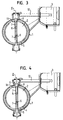
- FIG. 4 third variant of an inventive Blocking arrangement is largely consistent with the other two variants match.
- separate storage bins 9 are again provided, which, however, have a conical shape. The functioning is also described here as for the first variant.
- FIG. 5 shows a butterfly valve 2, which in its surrounding the axis of rotation II central region 12 has a greater thickness d 1 than in the two adjoining areas 13.
- the thickness d 1 of the central region 12 is selected to be correspondingly large.
- the two adjoining regions 13 have a thickness d 2 which only has to satisfy strength considerations and is therefore lower. The mass of the butterfly valve 2 is thereby reduced.
- the reduced thickness d 2 of the shut-off flap 2 in the regions 13 is made such that a type Z-shape of the shut-off flap 2 results in plan view in the direction of the axis of rotation II. That is, the withdrawal in the strength of the butterfly valve 2 is made once on one side and once on the other side of the butterfly valve 2, which thereby receives a two-fold point symmetry about its axis of rotation II. This results in a uniform weight distribution and a symmetrical stop on the half-shells. 5
- the butterfly valve 2 in the metal injection molding process be prepared. This gives you a high dimensional accuracy at relatively low production costs.
- shut-off invention All variants of the shut-off invention are characterized due to a good sealing function and low noise level. In addition, the production is inexpensive and inexpensive.
Landscapes
- Engineering & Computer Science (AREA)
- General Engineering & Computer Science (AREA)
- Mechanical Engineering (AREA)
- Chemical & Material Sciences (AREA)
- Combustion & Propulsion (AREA)
- Lift Valve (AREA)
- Valve Housings (AREA)
Abstract
Description
- Fig. 1
- eine perspektivische, teilweise geschnittene Darstellung einer erfindungsgemäßen Absperranordnung,
- Fig. 2
- einen Schnitt durch die Absperranordnung von Fig. 1,
- Fig. 3
- einen Querschnitt durch eine zweite Variante einer erfindungsgemäßen Absperranordnung,
- Fig. 4
- einen Querschnitt durch noch eine Variante einer erfindungsgemäßen Absperranordnung, und
- Fig. 5
- einen Schnitt durch einen Teil noch einer Variante einer erfindungsgemäßen Absperranordnung.
- 1
- Gehäuse
- 2
- Absperrklappe
- 3
- Unterdruckdose
- 4
- Innenwand von 1
- 5
- Halbschale
- 6
- Sackloch
- 7
- Halbwelle
- 8
- Durchtrittsöffnung
- 9
- Lagerbuchse
- 10
- Betätigungsstößel
- 11
- Anschlag
- 12
- mittlerer Bereich von 2
- 13
- Bereich von 2
- I
- Strömungsrichtung
- II
- Drehachse
- d1
- Stärke von 12
- d2
- Stärke von 13
Claims (10)
- Absperranordnung zum Absperren eines Fluidstroms, insbesondere Abgasstroms einer Kraftfahrzeugabgasanlage, mit einem Gehäuse (1), einer in dem Gehäuse (1) angeordneten, um eine quer zur Strömungsrichtung (1) verlaufende Achse (II) drehbaren Absperrklappe (2) und Mitteln (3) zur Betätigung der Absperrklappe,
dadurch gekennzeichnet, dass an der Innenwand (4) des Gehäuses (1) mindestens ein nach innen vorstehender Anschlag (5) für die Absperrklappe (2) vorgesehen ist, dessen Kontur einem Umfangsabschnitt der Absperrklappe (2) entspricht, so dass die Absperrklappe (2) in Sperrstellung mit einem Randbereich an dem Anschlag (5) anliegt. - Absperranordnung nach Anspruch 1,
dadurch gekennzeichnet, dass an zwei einander gegenüberliegenden Innenseiten (4) des Gehäuses (1) ein solcher Anschlag (5) vorgesehen ist und/oder dass sich die Anschläge (5) jeweils von einem Drehpunkt der Absperrklappe (2) zum anderen erstrecken. - Absperranordnung nach einem der vorhergehenden Ansprüche,
dadurch gekennzeichnet, dass der oder die Anschläge (5) derart angeordnet sind, dass die Absperrklappe (2) in Anschlagstellung einen Winkel von 90° mit der Strömungsrichtung (I) einschließt, oder derart, dass die Absperrklappe (2) in Anschlagstellung einen Winkel kleiner 90°, insbesondere ca. 80° bis ca. 85° mit der Strömungsrichtung (I) einschließt. - Absperranordnung nach einem der vorhergehenden Ansprüche,
dadurch gekennzeichnet, dass das Gehäuse (1) ein- oder mehrteilig ausgebildet ist und/oder dass das Gehäuse (1) durch ein Rohrstück gebildet ist. - Absperranordnung nach einem der vorhergehenden Ansprüche,
dadurch gekennzeichnet, dass der oder die Anschläge (5) je durch einen Rohrausschnitt gebildet sind, insbesondere durch Halbschalen, bevorzugt hergestellt als Stanzprägeteil. - Absperranordnung nach einem der vorhergehenden Ansprüche,
dadurch gekennzeichnet, dass die Absperrklappe (2) beidseitig gelagert ist, insbesondere durch je eine Halbwelle (7). - Absperranordnung nach einem der vorhergehenden Ansprüche,
dadurch gekennzeichnet, dass die Absperrklappe (2) eine solche Stärke aufweist, dass die Halbwellen (7) jeweils in eine Ausnehmung (6) in der Absperrklappe (2) eingesteckt werden können und/oder dass die Absperrklappe (2) im ihre Drehachse (II) umgebenden mittleren Bereich (12) eine größere Stärke (d1) aufweist als in den beidseits daran anschließenden Bereichen (13), wobei die Bereiche (13) verringerter Stärke (d2) bevorzugt mit zweifacher Punktsymmetrie zur Drehachse (II) ausgebildet sind, so dass sich bei Draufsicht in Richtung der Drehachse (II) eine Art Z-Form der Absperrklappe (2) ergibt. - Absperranordnung nach einem der vorhergehenden Ansprüche,
dadurch gekennzeichnet, dass die Halbwellen (7) an der Absperrklappe (2) mittels einer Laser-Durchstechnaht befestigt sind und/oder dass die Halbwellen (7) je einen Anschlag (11) zur Zentrierung der Absperrklappe (2) im Gehäuse (1) aufweisen. - Absperranordnung nach einem der vorhergehenden Ansprüche,
dadurch gekennzeichnet, dass die Absperrklappe (2) ein- oder mehrteilig ausgebildet ist und/oder dass die Absperrklappe (2) im Metallspritzgussverfahren hergestellt ist. - Absperranordnung nach einem der vorhergehenden Ansprüche,
dadurch gekennzeichnet, dass die Lager für die Halbwellen (7) aus Graphit, mit oder ohne Gewebeverstärkung, und/oder aus keramischen oder metallischen Lagerwerkstoffen bestehen und/oder dass ein separates Lagerelement (9) für die Lagerung der Absperrklappe (2) vorgesehen ist, wobei das Lagerelement (9) insbesondere eine rotationssymmetrische Kontur und/oder eine konische Form aufweist.
Applications Claiming Priority (2)
| Application Number | Priority Date | Filing Date | Title |
|---|---|---|---|
| DE20311260U DE20311260U1 (de) | 2003-07-22 | 2003-07-22 | Absperranordnung zum Absperren eines Fluidstroms |
| DE20311260U | 2003-07-22 |
Publications (1)
| Publication Number | Publication Date |
|---|---|
| EP1503062A1 true EP1503062A1 (de) | 2005-02-02 |
Family
ID=33495286
Family Applications (1)
| Application Number | Title | Priority Date | Filing Date |
|---|---|---|---|
| EP04017191A Withdrawn EP1503062A1 (de) | 2003-07-22 | 2004-07-21 | Absperranordnung zum Absperren eines Fluidstroms |
Country Status (2)
| Country | Link |
|---|---|
| EP (1) | EP1503062A1 (de) |
| DE (1) | DE20311260U1 (de) |
Cited By (4)
| Publication number | Priority date | Publication date | Assignee | Title |
|---|---|---|---|---|
| WO2006136213A1 (de) * | 2005-06-20 | 2006-12-28 | Emcon Technologies Germany (Augsburg) Gmbh | Ventil, insbesondere für eine kraftfahrzeug-abgasanlage |
| WO2014016161A1 (de) * | 2012-07-24 | 2014-01-30 | Friedrich Boysen Gmbh & Co. Kg | Lagersystem für eine welle |
| DE102021134312A1 (de) | 2021-12-22 | 2023-06-22 | Wagner Group Gmbh | Strömungsmittel zur Umkehr der Strömungsrichtung |
| EP4556763A3 (de) * | 2023-11-15 | 2025-06-04 | Hamilton Sundstrand Corporation | Modulares luftventilsystem |
Families Citing this family (1)
| Publication number | Priority date | Publication date | Assignee | Title |
|---|---|---|---|---|
| DE102011107024B4 (de) * | 2011-07-14 | 2019-02-07 | Friedrich Boysen Gmbh & Co. Kg | STEUEREINRICHTUNG und Verfahren zur Herstellung derselben |
Citations (9)
| Publication number | Priority date | Publication date | Assignee | Title |
|---|---|---|---|---|
| GB567751A (en) * | 1942-02-24 | 1945-03-01 | William Arnold Horrocks | Improvements in exhaust-pipes for internal-combustion engines |
| GB1014575A (en) * | 1964-07-03 | 1965-12-31 | Crane Ltd | Butterfly type of fluid control valves |
| US3661171A (en) * | 1970-05-12 | 1972-05-09 | Xomox Corp | Butterfly valve |
| US4491106A (en) * | 1982-11-29 | 1985-01-01 | Morris George Q | Throttle configuration achieving high velocity channel at partial opening |
| US4572478A (en) * | 1982-11-29 | 1986-02-25 | Vdo Adolf Schindling Ag | Throttle-valve connection piece |
| FR2606115A1 (fr) * | 1986-10-31 | 1988-05-06 | Peugeot | Vanne a papillon notamment pour vehicule automobile et son application a un carburateur |
| GB2245931A (en) * | 1990-07-10 | 1992-01-15 | Rover Group | I.c. engine air intake throttle body |
| US5669350A (en) * | 1993-09-02 | 1997-09-23 | Filterwerk Mann & Hummel Gmbh | Throttle device |
| US6138640A (en) * | 1998-06-30 | 2000-10-31 | Aisan Kogyo Kabushiki Kaisha | Intake control valve device for internal combustion engine |
Family Cites Families (17)
| Publication number | Priority date | Publication date | Assignee | Title |
|---|---|---|---|---|
| DE922800C (de) * | 1952-12-23 | 1955-01-24 | Kloeckner Humboldt Deutz Ag | Drosselklappe in einem kugelartigen Gehaeuse der Auspuffleitung zur Verstaerkung derBremswirkung |
| DE1991832U (de) * | 1968-05-31 | 1968-08-14 | Trox Gmbh Geb | Drosselklappe fuer insbesondere hochdruckanlagen. |
| DE3113004A1 (de) * | 1981-04-01 | 1982-10-21 | Schunk & Ebe Gmbh, 6301 Heuchelheim | Gleitkoerper |
| DE8120908U1 (de) * | 1981-07-16 | 1981-10-08 | Bowa GmbH, Apparate- und Behälterbau, 8261 Aschau | Rohrstutzen mit einer schwenkbaren abgasklappe |
| DE8129546U1 (de) * | 1981-10-09 | 1982-03-04 | Mtu Motoren- Und Turbinen-Union Friedrichshafen Gmbh, 7990 Friedrichshafen | "lagerung fuer ein verschlussteil" |
| DE3802243A1 (de) * | 1988-01-27 | 1989-08-10 | Daimler Benz Ag | Lagerung einer drosselklappenwelle im gehaeuse einer abgasleitung |
| DE3920189A1 (de) * | 1988-07-01 | 1990-01-04 | Luk Lamellen & Kupplungsbau | Fluessigkeitskupplung, wie foettinger-kupplung oder drehmomentwandler |
| GB9200339D0 (en) * | 1992-01-08 | 1992-02-26 | Btr Plc | Valve disc and drive shaft assembly |
| DE4305123C2 (de) * | 1993-02-19 | 1995-01-26 | Pierburg Gmbh | Anordnung einer Drosselklappe |
| US5427137A (en) * | 1993-12-15 | 1995-06-27 | Bowen; James H. | Fluid shut off valve and fill level indication |
| DE19500501A1 (de) * | 1994-06-28 | 1996-01-04 | Schatz Thermo Engineering | Verfahren und Vorrichtung zur Steuerung des Ladungswechsels von Verbrennungsmotoren durch Ventile |
| DE9419537U1 (de) * | 1994-12-06 | 1995-02-02 | Fa. J. Eberspächer, 73730 Esslingen | Abgasklappen-Anordnung |
| DE19500475C2 (de) * | 1995-01-10 | 2001-09-27 | Schatz Thermo Gastech Gmbh | Absperr- oder Drosselventil mit drehbarer Ventilklappe |
| DE19524510A1 (de) * | 1995-07-05 | 1997-01-09 | Klein Schanzlin & Becker Ag | Fluidgeschmiertes Gleitlager |
| DE20002784U1 (de) * | 2000-02-16 | 2000-07-13 | Albert Handtmann Metallgußwerk GmbH & Co. KG, 88400 Biberach | Auf einer Welle angeordnete Drosselklappe |
| DE10140410A1 (de) * | 2001-08-23 | 2003-03-13 | Siemens Ag | Drosselklappenanordnung |
| DE10151605A1 (de) * | 2001-10-18 | 2003-05-08 | Euroflamm Gmbh | Gleitelement |
-
2003
- 2003-07-22 DE DE20311260U patent/DE20311260U1/de not_active Expired - Lifetime
-
2004
- 2004-07-21 EP EP04017191A patent/EP1503062A1/de not_active Withdrawn
Patent Citations (9)
| Publication number | Priority date | Publication date | Assignee | Title |
|---|---|---|---|---|
| GB567751A (en) * | 1942-02-24 | 1945-03-01 | William Arnold Horrocks | Improvements in exhaust-pipes for internal-combustion engines |
| GB1014575A (en) * | 1964-07-03 | 1965-12-31 | Crane Ltd | Butterfly type of fluid control valves |
| US3661171A (en) * | 1970-05-12 | 1972-05-09 | Xomox Corp | Butterfly valve |
| US4491106A (en) * | 1982-11-29 | 1985-01-01 | Morris George Q | Throttle configuration achieving high velocity channel at partial opening |
| US4572478A (en) * | 1982-11-29 | 1986-02-25 | Vdo Adolf Schindling Ag | Throttle-valve connection piece |
| FR2606115A1 (fr) * | 1986-10-31 | 1988-05-06 | Peugeot | Vanne a papillon notamment pour vehicule automobile et son application a un carburateur |
| GB2245931A (en) * | 1990-07-10 | 1992-01-15 | Rover Group | I.c. engine air intake throttle body |
| US5669350A (en) * | 1993-09-02 | 1997-09-23 | Filterwerk Mann & Hummel Gmbh | Throttle device |
| US6138640A (en) * | 1998-06-30 | 2000-10-31 | Aisan Kogyo Kabushiki Kaisha | Intake control valve device for internal combustion engine |
Cited By (5)
| Publication number | Priority date | Publication date | Assignee | Title |
|---|---|---|---|---|
| WO2006136213A1 (de) * | 2005-06-20 | 2006-12-28 | Emcon Technologies Germany (Augsburg) Gmbh | Ventil, insbesondere für eine kraftfahrzeug-abgasanlage |
| WO2014016161A1 (de) * | 2012-07-24 | 2014-01-30 | Friedrich Boysen Gmbh & Co. Kg | Lagersystem für eine welle |
| DE102012212998B4 (de) | 2012-07-24 | 2023-09-07 | Friedrich Boysen Gmbh & Co. Kg | Lagersystem für eine Welle |
| DE102021134312A1 (de) | 2021-12-22 | 2023-06-22 | Wagner Group Gmbh | Strömungsmittel zur Umkehr der Strömungsrichtung |
| EP4556763A3 (de) * | 2023-11-15 | 2025-06-04 | Hamilton Sundstrand Corporation | Modulares luftventilsystem |
Also Published As
| Publication number | Publication date |
|---|---|
| DE20311260U1 (de) | 2004-12-02 |
Similar Documents
| Publication | Publication Date | Title |
|---|---|---|
| DE102014114968B4 (de) | Regelvorrichtung für eine Verbrennungskraftmaschine | |
| EP2728156B1 (de) | Regelvorrichtung für eine Verbrennungskraftmaschine | |
| DE102008003177A1 (de) | Abgasrückführventil für ein Kraftfahrzeug | |
| EP1909005A1 (de) | Drosselklappenvorrichtung für eine Verbrennungskraftmaschine | |
| DE9419537U1 (de) | Abgasklappen-Anordnung | |
| DE102015209823A1 (de) | Betätigungseinrichtung | |
| DE102007025516A1 (de) | Kugelhahn zum Absperren und steuerbaren Öffnen einer Rohrleitung | |
| EP2079911B1 (de) | Drosselklappenstutzen | |
| DE2849281C2 (de) | ||
| DE102006021185A1 (de) | Verschlussklappe für einen Abgasturbolader | |
| DE102008034341A1 (de) | Doppelklappenventil | |
| EP1936151B1 (de) | Verfahren zum Herstellen einer Vorrichtung zur Steuerung des Durchflusses eines gasförmigen oder flüssigen Mediums | |
| EP1503062A1 (de) | Absperranordnung zum Absperren eines Fluidstroms | |
| EP3615787B1 (de) | Regelvorrichtung für eine verbrennungskraftmaschine | |
| EP2653710B1 (de) | Ventilvorrichtung für eine Verbrennungskraftmaschine | |
| DE102012224093A1 (de) | Ventilvorrichtung für ein Kraftfahrzeug | |
| WO2021144183A1 (de) | Ventilvorrichtung für eine verbrennungskraftmaschine | |
| EP2670934B1 (de) | Kraftfahrzeugschloss | |
| DE10330225B4 (de) | Klappenvorrichtung für eine Verbrennungskraftmaschine | |
| EP1062445A1 (de) | Thermische armaturensicherung zum automatischen absperren von leitungen | |
| DE102011017452A1 (de) | Betätigungseinrichtung in einem Kraftfahrzeug | |
| WO2006136213A1 (de) | Ventil, insbesondere für eine kraftfahrzeug-abgasanlage | |
| DE10334475B4 (de) | Klappensystem für eine Verbrennungskraftmaschine | |
| DE112017007999T5 (de) | Ventil mit Klapperschutz, Abgasleitung mit einem solchen Ventil und Verfahren zur Herstellung eines solchen Ventils | |
| EP1649200B1 (de) | Teileinheit für eine zusatzsteuerventileinrichtung für einen einlasskanal einer kolbenbrennkraftmaschine |
Legal Events
| Date | Code | Title | Description |
|---|---|---|---|
| PUAI | Public reference made under article 153(3) epc to a published international application that has entered the european phase |
Free format text: ORIGINAL CODE: 0009012 |
|
| AK | Designated contracting states |
Kind code of ref document: A1 Designated state(s): AT BE BG CH CY CZ DE DK EE ES FI FR GB GR HU IE IT LI LU MC NL PL PT RO SE SI SK TR |
|
| AX | Request for extension of the european patent |
Extension state: AL HR LT LV MK |
|
| 17P | Request for examination filed |
Effective date: 20050407 |
|
| 17Q | First examination report despatched |
Effective date: 20050513 |
|
| AKX | Designation fees paid |
Designated state(s): CZ DE FR GB IT |
|
| STAA | Information on the status of an ep patent application or granted ep patent |
Free format text: STATUS: THE APPLICATION IS DEEMED TO BE WITHDRAWN |
|
| 18D | Application deemed to be withdrawn |
Effective date: 20060324 |