EP2079911B1 - Drosselklappenstutzen - Google Patents
Drosselklappenstutzen Download PDFInfo
- Publication number
- EP2079911B1 EP2079911B1 EP07821073A EP07821073A EP2079911B1 EP 2079911 B1 EP2079911 B1 EP 2079911B1 EP 07821073 A EP07821073 A EP 07821073A EP 07821073 A EP07821073 A EP 07821073A EP 2079911 B1 EP2079911 B1 EP 2079911B1
- Authority
- EP
- European Patent Office
- Prior art keywords
- throttle flap
- throttle
- shaft
- connecting piece
- edge
- Prior art date
- Legal status (The legal status is an assumption and is not a legal conclusion. Google has not performed a legal analysis and makes no representation as to the accuracy of the status listed.)
- Ceased
Links
Images


Classifications
-
- F—MECHANICAL ENGINEERING; LIGHTING; HEATING; WEAPONS; BLASTING
- F02—COMBUSTION ENGINES; HOT-GAS OR COMBUSTION-PRODUCT ENGINE PLANTS
- F02D—CONTROLLING COMBUSTION ENGINES
- F02D9/00—Controlling engines by throttling air or fuel-and-air induction conduits or exhaust conduits
- F02D9/08—Throttle valves specially adapted therefor; Arrangements of such valves in conduits
- F02D9/10—Throttle valves specially adapted therefor; Arrangements of such valves in conduits having pivotally-mounted flaps
-
- F—MECHANICAL ENGINEERING; LIGHTING; HEATING; WEAPONS; BLASTING
- F02—COMBUSTION ENGINES; HOT-GAS OR COMBUSTION-PRODUCT ENGINE PLANTS
- F02D—CONTROLLING COMBUSTION ENGINES
- F02D9/00—Controlling engines by throttling air or fuel-and-air induction conduits or exhaust conduits
- F02D9/08—Throttle valves specially adapted therefor; Arrangements of such valves in conduits
- F02D9/10—Throttle valves specially adapted therefor; Arrangements of such valves in conduits having pivotally-mounted flaps
- F02D9/1005—Details of the flap
- F02D9/101—Special flap shapes, ribs, bores or the like
- F02D9/1015—Details of the edge of the flap, e.g. for lowering flow noise or improving flow sealing in closed flap position
-
- F—MECHANICAL ENGINEERING; LIGHTING; HEATING; WEAPONS; BLASTING
- F02—COMBUSTION ENGINES; HOT-GAS OR COMBUSTION-PRODUCT ENGINE PLANTS
- F02D—CONTROLLING COMBUSTION ENGINES
- F02D9/00—Controlling engines by throttling air or fuel-and-air induction conduits or exhaust conduits
- F02D9/08—Throttle valves specially adapted therefor; Arrangements of such valves in conduits
-
- F—MECHANICAL ENGINEERING; LIGHTING; HEATING; WEAPONS; BLASTING
- F16—ENGINEERING ELEMENTS AND UNITS; GENERAL MEASURES FOR PRODUCING AND MAINTAINING EFFECTIVE FUNCTIONING OF MACHINES OR INSTALLATIONS; THERMAL INSULATION IN GENERAL
- F16K—VALVES; TAPS; COCKS; ACTUATING-FLOATS; DEVICES FOR VENTING OR AERATING
- F16K3/00—Gate valves or sliding valves, i.e. cut-off apparatus with closing members having a sliding movement along the seat for opening and closing
- F16K3/02—Gate valves or sliding valves, i.e. cut-off apparatus with closing members having a sliding movement along the seat for opening and closing with flat sealing faces; Packings therefor
- F16K3/04—Gate valves or sliding valves, i.e. cut-off apparatus with closing members having a sliding movement along the seat for opening and closing with flat sealing faces; Packings therefor with pivoted closure members
Definitions
- the invention relates to a throttle body with a housing in which a through-hole is formed, which is closed by a arranged on a throttle shaft and associated with this throttle valve cross-section, wherein the throttle shaft with its lateral ends in bearing recesses of the housing about an axis of rotation is pivotally mounted, wherein the radially encircling edge of the throttle is annular and has a reduced thickness compared to the thickness of the throttle, wherein the two opposite ring sides of the radially encircling annular edge of the throttle valve extend symmetrically to a rotational axis intersecting radials of the throttle shaft.
- the recess has such a depth beyond the axis of rotation of the throttle valve shaft depth, that the throttle valve extends symmetrically to the axis of rotation radially.
- the radially directed annular surface of the throttle valve is made by turning.
- the throttle valve is mounted on the throttle shaft in such a way that even the region of the throttle flap which is not reduced in thickness extends symmetrically with respect to the radial axis of the throttle flap which intersects the axis of rotation.
- the object of the invention is to provide a throttle body of the type mentioned above, which avoids these disadvantages and has a reduced risk of contamination and ice formation and blocking the throttle at its radially peripheral area.
- This design results in a low production time for the radially encircling annular edge.
- the radial depth of the flattening in the throttle flap shaft can be reduced and therefore only reduced material removal may be required, since it is not necessary to take into account the thickness of the throttle flap in its central attachment region but only in its region of the edge.
- the greater thickness of the throttle flap ensures in its central region a high stability of the throttle valve, while the radially encircling annular edge due to its smaller thickness leads to a lower accumulation of dirt and moisture in this edge region, so that accordingly also the possibility of ice formation and As a result, a blockage of the throttle valve is reduced.
- the circumferential annular edge of the throttle valve has a thickness of the order of about 1 mm.
- the throttle may have a thickness on the order of between approximately 1.5 mm and 3 mm outside the radially encircling annular edge.
- the throttle valve can be produced in that the throttle valve is a stamped component.
- the radially directed circumferential annular surface of the annular edge of reduced thickness is a punching surface, then the percentage of the smooth cut in relation to the portion of the punch cut is very large due to the smaller material thickness in the edge region, whereby the possibility of accumulation of dirt and moisture in this region is largely eliminated ,
- the punching surface is a Repassierstanz Structure (precision punching surface), wherein the Repassierstanzvorgang takes place after the generation of the radially encircling edge, so a smooth cut portion of approximately 100% at the radial directed circumferential annular surface of the annular edge reaches.
- the flattening of the throttle shaft may form a receiving groove having a depth extending beyond the rotational axis of the throttle shaft.
- the region of the throttle flap which is enclosed by the annular edge is preferably flat.
- the object of the invention is achieved in that the flattening is formed tangentially on one side of the axis of rotation of the throttle shaft, wherein the throttle has a central, lying flat on the flat bearing area, to each other opposite to each other to the contour of the throttle shaft cuddly quarter-round Area adjoins, which merges into a plane of rotation approximately radially radial flap area.
- the contact area of the throttle flap is greater than the flattening of the throttle valve shaft transversely to and / or in the longitudinal extent of the throttle valve shaft, a displacement of the preassembled throttle valve on the throttle valve shaft for assembly purposes and a self-centering of the throttle valve in the throttle body is possible.
- the throttle valve can be fastened to the throttle shaft by means of one or more radial screws that are radial to the throttle valve shaft, which project through bores in the throttle valve and are screwed into threaded bores in the throttle shaft.
- the illustrated throttle body for an air intake duct of a motor vehicle have a housing 1 with a through-passage opening 2, which can be closed by a throttle valve 3, 3 '.
- the throttle valve 3, 3 ' is arranged on a throttle valve shaft 4, 4', which extends transversely to the passage opening 2 and protrude with their lateral ends 5 in bearing recesses 6 of the housing 1 and are pivotally mounted about a rotation axis 2.
- the throttle shaft 4 has a flattening 8, 8 ', on which the throttle valve 3, 3' in support and with the throttle shaft 3, 3 'is connected.
- the flattening 8 is formed tangentially on one side of the axis of rotation 7 of the throttle shaft 4.
- the throttle valve 3 is a stamped / bent part made of a metal sheet and has a diagonally continuously extending bead 14.
- the bead 14 has a central, planar contact region 15 of slightly greater extent transversely to the throttle shaft 4 than the width of the flattening 8.
- a radially encircling edge 18 is annularly formed on the throttle valve 3 and has a reduced thickness 20 with respect to the thickness 19 of the sheet metal of the throttle valve 3.
- the annular edge 18 is formed by a one-sided axial stamping on the flattening 8 of the throttle shaft 4 side facing away from the throttle valve 3.
- edge 18 of the radially outer edge of the throttle valve 3 is on the side facing away from the flattening 8 stepped, while the other side of the throttle valve 3 has no such stage.
- the edge 18 extends radially to the axis of rotation. 7
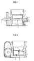
- the flattening 8 ' forms a receiving groove 21 for the throttle valve 4', which has a depth extending beyond the axis of rotation 7.
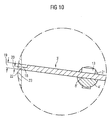
- FIGS. 1 to 5 also owns the embodiment of FIGS. 6 to 10 a radially encircling rim 18 having a reduced thickness 20 with respect to the thickness 10 of the sheet metal of the throttle valve 3 '.
- the annular edge 18 is formed by a one-sided Axiallessness on the flattening 8 'of the throttle shaft 4 side facing away from the throttle valve 3 stages, wherein the edge 18 extends radially to the axis of rotation 7.
- the flattening 8 'facing side of the throttle valve 3' has no such stage.
- the throttle valve 3, 3 'on the flat 8, 8' slidably adjusts its position of the through hole 2 and can now be screwed in this adjusted position by means of screws 10 on the throttle shaft 4, 4 '.
Landscapes
- Engineering & Computer Science (AREA)
- General Engineering & Computer Science (AREA)
- Mechanical Engineering (AREA)
- Chemical & Material Sciences (AREA)
- Combustion & Propulsion (AREA)
- Lift Valve (AREA)
Abstract
Description
- Die Erfindung bezieht sich auf einen Drosselklappenstutzen mit einem Gehäuse, in dem eine durchgehende Durchgangsöffnung ausgebildet ist, die durch eine auf einer Drosselklappenwelle angeordneten und mit dieser verbundenen Drosselklappe runden Querschnitts verschließbar ist, wobei die Drosselklappenwelle mit ihren seitlichen Enden in Lagerausnehmungen des Gehäuses um eine Drehachse schwenkbar gelagert ist, wobei der radial umlaufende Rand der Drosselklappe ringartig ausgebildet ist und eine gegenüber der Dicke der Drosselklappe reduzierte Dicke aufweist, wobei die beiden einander gegenüberliegenden Ringseiten des radial umlaufenden ringartigen Randes der Drosselklappe sich symmetrisch zu einer die Drehachse schneidenden Radialen der Drosselklappenwelle erstrecken.
- Bei derartigen Drosselklappenstutzen ist es bekannt, die Drosselklappenwelle mit einer nutartigen Vertiefung zu versehen, in die dann die Drosselklappe eingelegt und durch Schrauben mit der Drosselklappenwelle verbunden wird.
- Dabei besitzt die Vertiefung eine derart über die Drehachse der Drosselklappenwelle hinausgehende Tiefe, dass die Drosselklappe sich symmetrisch zu Drehachse radial erstreckt.
- Die radial gerichtete Ringfläche der Drosselklappe wird durch Drehen hergestellt.
- Dieser Herstellungsvorgang ist zeitaufwendig.
- Dies trifft auch auf den Herstellungsvorgang für die nutartige Vertiefung zu, da diese eine große Tiefe besitzt, was einen hohen Materialabtrag erfordert.
- Damit ist aber auch die erforderliche Herstellungszeit sowie der Werkzeugverschleiß groß.
- Aus der
DE 197 14 717 A1 ist ein Drosselklappenstutzen der eingangs genannten Art bekannt. Dabei ist die Drosselklappe derart auf der Drosselklappenwelle befestigt, dass auch der in seiner Dicke nicht reduzierte Bereich der Drosselklappe sich symmetrisch zu der die Drehachse schneidenden Radialen der Drosselklappe erstreckt. - Aufgabe der Erfindung ist es einen Drosselklappenstutzen der eingangs genannten Art zu schaffen, der diese Nachteile vermeidet und eine verringerte Gefahr der Verschmutzung und Eisbildung sowie Blockierung der Drosselklappe an ihrem radial umlaufenden Umfangsbereich aufweist.
- Aus der
US-5081972 ist ein Droselklappenstutzen bekannt in dem, die Drosselklappe auf einer sich in Längserstreckung der Drosselklappenwelle an der Drosselklappenwelle ausgebildeten Abflachung in Auflage und mit der Drosselklappenwelle verbunden ist, wobei der radial umlaufende ringartige Rand der Drosselklappe eine einseitige Axialprägung der Drosselklappe auf der der Abflachung der Drosselklappenwelle abgewandten Seite der Drosselklappe ist. - Durch diese Ausbildung ergibt sich eine geringe Herstellungszeit für den radial umlaufenden ringartigen Rand.
- Dabei kann die radiale Tiefe der Abflachung in der Drosselklappewelle reduziert und damit nur geringeren Materialabtrag benötigend ausgebildet sein, da nicht die Dicke der Drosselklappe in ihrem mittleren Befestigungsbereich sondern nur in ihren Bereich des Randes dazu berücksichtigt werden muss.
- Die symmetrische Erstreckung der beiden Ringseiten des ringartigen Randes führt zu einem einwandfreien Schließvorgang der Durchgangsöffnung.
- Dabei gewährleistet die größere Dicke der Drosselklappe in ihrem mittleren Bereich eine hohe Stabilität der Drosselklappe, während der radial umlaufende ringartige Rand aufgrund seiner geringeren Dicke zu einer geringeren Ansammlung von Schmutz und Feuchtigkeit in diesem Randbereich führt, so dass sich entsprechend auch die Möglichkeit einer Eisbildung und daraus resultierend eine Blockierung der Drosselklappe verringert.
- Weiterhin ist durch die Verwendbarkeit eines normalen Fräswerkzeugs zur Erzeugung der Abflachung diese einfach herstellbar.
- Vorzugsweise weist der umlaufende ringartige Rand der Drosselklappe eine Dicke in der Größenordnung von etwa 1 mm auf.
- Die Drosselklappe kann außerhalb des radial umlaufenden ringartigen Randes eine Dicke in der Größenordnung zwischen annähernd 1,5 mm und 3 mm aufweisen.
- In kurzen Taktzeiten ist die Drosselklappe dadurch herstellbar, dass die Drosselklappe ein Stanzbauteil ist.
- Ist die radial gerichtete umlaufende Ringfläche des ringartigen Randes reduzierter Dicke eine Stanzfläche, so ist aufgrund der geringeren Materialdicke im Randbereich der prozentuale Anteil des Glattschnitts gegenüber dem Anteil des Stanzabrisses sehr groß, wodurch die Möglichkeit einer Ansammlung von Schmutz und Feuchtigkeit in diesem Bereich weitgehend eliminiert ist.
- Ist die Stanzfläche eine Repassierstanzfläche (Präzisionsstanzfläche), wobei der Repassierstanzvorgang nach der Erzeugung des radial umlaufenden Randes erfolgt, so wird ein Glattschnittanteil von annähernd 100 % an der radial gerichteten umlaufenden Ringfläche des ringartigen Randes erreicht.
- Die Abflachung der Drosselwelle kann eine Aufnahmenut bilden, die eine über die Drehachse der Drosselklappenwelle hinaus reichende Tiefe aufweist.
- Dabei ist vorzugsweise der von dem ringartigen Rand umschlossene Bereich der Drosselklappe flächig ausgebildet.
- Die Aufgabe der Erfindung wird dadurch gelöst, dass die Abflachung tangential auf einer Seite der Drehachse der Drosselklappenwelle ausgebildet ist, wobei die Drosselklappe einen mittigen, flach auf der Abflachung aufliegenden Anlagebereich besitzt, an den sich einander gegenüberliegend jeweils ein an die Kontur der Drosselklappenwelle anschmiegender viertelrundartiger Bereich anschließt, der in einen zur Drehachse annähernd radialen Klappenbereich übergeht.
- Dies erlaubt eine Abflachung von z. B. nur 2 bis 2,5 mm Tiefe, wodurch sich ein besonders niedriger erforderlicher Materialabtrag ergibt.
- Ist dabei der Anlagebereich der Drosselklappe sich quer zur und/oder in Längserstreckung der Drosselklappenwelle größer als die Abflachung der Drosselklappenwelle, so ist ein Verschieben der vormontierten Drosselklappe auf der Drosselklappenwelle zu Montagezwecken und einer Selbstzentrierung der Drosselklappe im Drosselklappenstutzen möglich.
- In einfacher Weise ist die Drosselklappe durch eine oder mehrere zur Drosselklappenwelle radiale Schrauben an der Drosselklappenwelle befestigbar, die durch Bohrungen in der Drosselklappe hindurchragen und in Gewindebohrungen der Drosselklappenwelle eingeschraubt sind.
- Ist dabei der Durchmesser der Bohrungen größer ist als der Durchmesser der Schrauben, so ermöglicht dies auf einfache Weise das Verschieben der vormontierten Drosselklappe, bevor sie endgültig mit der Drosselklappenwelle fest verbunden wird.
- Ausführungsbeispiele der Erfindung sind in der Zeichnung dargestellt und werden im Folgenden näher beschrieben. Es zeigen
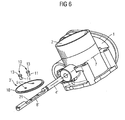
- Figur 1
- eine perspektivische Explosionsansicht eines ersten Ausführungsbeispiels eines Drosselklappen-Stutzens;
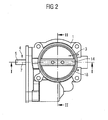
- Figur 2
- eine Ansicht des Drosselklappenstutzens nach
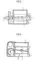
Figur 1 ; - Figur 3
- einen Schnitt entlang der Linie I - I in
Figur 2 ; - Figur 4
- einen Schnitt entlang der Linie II - II in
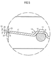
Figur 2 ; - Figur 5
- einen vergrößerten Ausschnitt "X" aus
Figur 4 ; - Figur 6
- eine perspektivische Explosionsansicht eines zweiten Ausführungsbeispiels eines Drosselklappenstutzens;
- Figur 7
- eine Ansicht des Drosselklappenstutzens nach
Figur 6 ; - Figur 8
- einen Schnitt entlang der Linie III - III in
Figur 7 ; - Figur 9
- einen Schnitt entlang der Linie IV - IV in
Figur 7 ; - Figur 10
- einen vergrößerten Ausschnitt "Y" aus
Figur 9 . - Die dargestellten Drosselklappenstutzen für einen Luftansaugkanal eines Kraftfahrzeugs weisen ein Gehäuse 1 mit einer durchgehenden Durchgangsöffnung 2 auf, die durch eine Drosselklappe 3, 3' verschließbar ist.
- Die Drosselklappe 3, 3' ist an einer Drosselklappenwelle 4, 4' angeordnet, die sich quer zur Durchgangsöffnung 2 erstreckt und mit ihren seitlichen Enden 5 in Lagerausnehmungen 6 des Gehäuses 1 ragen und um eine Drehachse 2 schwenkbar gelagert sind.
- Mit der Drosselklappenwelle 4, 4' ist die Drosselklappe 3, 3' aus zwischen einer in Durchströmrichtung der Durchgangsöffnung 2 gerichteten Offenstellung und einer quer zur Durchgangsöffnung 2 gerichteten Schließstellung um die Drehachse 7 schwenkbar antreibbar.
- Die Drosselklappenwelle 4 weist eine Abflachung 8, 8' auf, auf der die Drosselklappe 3, 3' in Auflage und mit der Drosselklappenwelle 3, 3' verbunden ist.
- Dazu sind in der Drosselklappe 3, 3' in einem Abstand zueinander zwei Bohrungen 9 ausgebildet, durch die jeweils eine Schraube 10 hindurchragt, die mit ihrem Gewindeschaft 11 in eine entsprechende Gewindebohrung 12 der Drosselklappe 3, 3' eingeschraubt ist, wobei die Schraubenköpfe 13 der Schrauben 10 die Drosselklappe 3, 3' gegen die Drosselklappenwelle 4, 4' pressen.
- Bei dem Ausführungsbeispiel der
Figuren 1 bis 5 ist die Abflachung 8 tangential auf einer Seite der Drehachse 7 der Drosselklappenwelle 4 ausgebildet. - Die Drosselklappe 3 ist ein Stanz-/Biegeteil aus einem Blech und besitzt eine sich diagonal durchgehend erstreckende Sicke 14.
- Die Sicke 14 weist einen mittigen, ebenen Anlagebereich 15 etwas größerer Erstreckung quer zur Drosselklappenwelle 4 als der Breite der Abflachung 8 auf.
- An den ebenen Anlagebereich 15 schließen sich beidseitig jeweils ein etwa viertelrunder Bereich 16 an, der sich an die Kontur der Drosselklappenwelle 4 etwa anschmiegt.
- Diese viertelrunden Bereiche 16 gehen dann in zur Drehachse 7 annähernd radiale Klappenbereiche 17 über.
- Mit Ausnahme des Bereichs der Sicke 14 ist ein radial umlaufender Rand 18 an der Drosselklappe 3 ringartig ausgebildet und besitzt eine gegenüber der Dicke 19 des Blechs der Drosselklappe 3 reduzierte Dicke 20.
- Dabei ist der ringartige Rand 18 durch eine einseitige Axialprägung auf der der Abflachung 8 der Drosselklappenwelle 4 abgewandten Seite der Drosselklappe 3 gebildet.
- Durch den Rand 18 ist der radial äußere Rand der Drosselklappe 3 auf der der Abflachung 8 abgewanden Seite stufig ausgebildet, während die andere Seite der Drosselklappe 3 keine derartige Stufe besitzt.
- Der Rand 18 erstreckt sich radial zur Drehachse 7.
- Bei dem Ausführungsbeispiel der
Figuren 6 bis 10 bildet die Abflachung 8' eine Aufnahmenut 21 für die Drosselklappe 4', die eine über die Drehachse 7 hinausreichende Tiefe besitzt. - Entsprechend dem Ausführungsbeispiel der
Figuren 1 bis 5 besitzt auch das Ausführungsbeispiel derFiguren 6 bis 10 einen radial umlaufenden Rand 18, der eine gegenüber der Dicke 10 des Blechs der Drosselklappe 3' reduzierte Dicke 20 aufweist. - Auch hier ist der ringartige Rand 18 durch eine einseitige Axialprägung auf der der Abflachung 8' der Drosselklappenwelle 4 abgewandten Seite der Drosselklappe 3 stufig ausgebildet, wobei sich der Rand 18 radial zur Drehachse 7 erstreckt.
Die der Abflachung 8' zugewandte Seite der Drosselklappe 3' weist keine derartige Stufe auf. - Zur Montage wird die Drosselklappe 3, 3' auf die Abflachung 8, 8' der bereits in dem Gehäuse 1 montierten Drosselklappenwelle 4, 4' aufgelegt und die durch die Bohrungen 9 hindurchgeführten Schrauben 10 so weit in die Gewindebohrungen 12 eingeschraubt, dass sich die Drosselklappe 3, 3' gerade noch auf der Abflachung 8, 8' verschieben lässt.
- Danach erfolgt eine Verschwenkung der Drosselklappe 3, 3' in die Schließstellung, wobei die radial gerichtete umlaufende Ringfläche 22 der Drosselklappe 3, 3' an der zylindrischen Innenwand 23 der Durchgangsöffnung 2 zur Anlage kommt.
- Dabei passt die Drosselklappe 3, 3' sich auf der Abflachung 8, 8' verschiebend ihre Position der Durchgangsöffnung 2 an und kann nun in dieser angepassten Position mittels der Schrauben 10 auf der Drosselklappenwelle 4, 4' festgeschraubt werden.
Claims (11)
- Drosselklappenstutzen mit einem Gehäuse (1), in dem eine durchgehende Durchgangsöffnung (2) ausgebildet ist, die durch eine auf einer Drosselklappenwelle (4,4') angeordneten und mit dieser verbundenen Drosselklappe (3,3') runden Querschnitts verschließbar ist, wobei die Drosselklappenwelle (4,4') mit ihren seitlichen Enden in Lagerausnehmungen des Gehäuses um eine Drehachse (7) schwenkbar gelagert ist, wobei der radial umlaufende Rand (18) der Drosselklappe (3,3') ringartig ausgebildet ist und eine gegenüber der Dicke (19) der Drosselklappe (3,3') reduzierte Dicke (20) aufweist, wobei die beiden einander gegenüberliegenden Ringseiten des radial umlaufenden ringartigen Randes 18 der Drosselklappe (3,3') sich symmetrisch zu einer die Drehachse (7) schneidenden Radialen der Drosselklappenwelle (4,4') erstrecken, wobei die Drosselklappe (3,3') auf einer sich in Längserstreckung der Drosselklappenwelle (4,4') an der, Drosselklappenwelle (4,4') ausgebildeten Abflachung (8,8') in Auflage und mit der Drosselklappenwelle (4,4') verbunden ist, wobei der radial umlaufende ringartige Rand (18) der Drosselklappe (3,3') eine einseitige Axialprägung der Drosselklappe (3,3') auf der der Abflachung der Drosselklappenwelle abgewandten Seite der Drosselklappe (3,3') ist dadurch gekennzeichnet, dass die Abflachung (8) tangential auf einer Seite der Drehachse (7) der Drosselklappenwelle (4) ausgebildet ist, wobei die Drosselklappe (3) einen mittigen, flach auf der Abflachung (8) aufliegenden Anlagebereich (15) besitzt, an den sich einander gegenüberliegend jeweils ein an die Kontur der Drosselklappenwelle (4) anschmiegender viertelrundartiger Bereich (16) anschließt, der in einen zur Drehachse (7) annähernd radialen Klappenbereich (17) übergeht.
- Drosselklappenstutzen nach Anspruch 1, dadurch gekennzeichnet, dass der umlaufende ringartige Rand (18) der Drosselklappe (3, 3') eine Dicke (20) von etwa 1 mm aufweist.
- Drosselklappenstutzen nach einem der vorhergehenden Ansprüche, dadurch gekennzeichnet, dass die Drosselklappe (3, 3') außerhalb des radial umlaufenden ringartigen Randes (18) eine Dicke (19) zwischen annähernd 1,5 mm und 3 mm aufweist.
- Drosselklappenstutzen nach einem der vorhergehenden Ansprüche, dadurch gekennzeichnet, dass die Drosselklappe (3, 3') ein Stanzbauteil ist.
- Drosselklappenstutzen nach einem der vorhergehenden Ansprüche, dadurch gekennzeichnet, dass die radial gerichtete umlaufende Ringfläche (22) des ringartigen Randes (18) reduzierter Dicke (20) eine Stanzfläche ist.
- Drosselklappenstutzen nach Anspruch 5, dadurch gekennzeichnet, dass die Stanzfläche eine Repassierstanzfläche (Präzisionsstanzfläche) ist.
- Drosselklappenstutzen nach einem der vorhergehenden Ansprüche, dadurch gekennzeichnet, dass die Abflachung (8') der Drosselklappenwelle (4') eine Aufnahmenut (21) bildet, die eine über die Drehachse (7) der Drosselklappenwelle (4') hinaus reichende Tiefe aufweist.
- Drosselklappenstutzen nach Anspruch 7, dadurch gekennzeichnet, dass der von dem ringartigen Rand (18) umschlossene Bereich der Drosselklappe (3') flächig ausgebildet ist.
- Drosselklappenstutzen nach Anspruch 8, dadurch gekennzeichnet, dass der Anlagebereich (15) der Drosselklappe (3) sich quer zur und/oder in Längserstreckung der Drosselklappenwelle (4) größer ist als die Abflachung (8) der Drosselklappenwelle (4).
- Drosselklappenstutzen nach einem der vorhergehenden Ansprüche, dadurch gekennzeichnet, dass die Drosselklappe (3, 3') durch eine oder mehrere zur Drosselklappenwelle (4, 4') radiale Schrauben (10) an der Drosselklappenwelle (4, 4') befestigbar ist, die durch Bohrungen (9) in der Drosselklappe (3, 3') hindurchragen und in Gewindebohrungen (12) der Drosselklappenwelle (4, 4') eingeschraubt sind.
- Drosselklappenstutzen nach Anspruch 10, dadurch gekennzeichnet, dass der Durchmesser der Bohrungen (9) größer ist als der Durchmesser der Schrauben (10).
Applications Claiming Priority (2)
| Application Number | Priority Date | Filing Date | Title |
|---|---|---|---|
| DE102006048179A DE102006048179A1 (de) | 2006-10-10 | 2006-10-10 | Drosselklappenstutzen |
| PCT/EP2007/060704 WO2008043754A1 (de) | 2006-10-10 | 2007-10-09 | Drosselklappenstutzen |
Publications (2)
| Publication Number | Publication Date |
|---|---|
| EP2079911A1 EP2079911A1 (de) | 2009-07-22 |
| EP2079911B1 true EP2079911B1 (de) | 2011-12-14 |
Family
ID=38846617
Family Applications (1)
| Application Number | Title | Priority Date | Filing Date |
|---|---|---|---|
| EP07821073A Ceased EP2079911B1 (de) | 2006-10-10 | 2007-10-09 | Drosselklappenstutzen |
Country Status (5)
| Country | Link |
|---|---|
| EP (1) | EP2079911B1 (de) |
| KR (1) | KR101406405B1 (de) |
| CN (1) | CN101523032A (de) |
| DE (1) | DE102006048179A1 (de) |
| WO (1) | WO2008043754A1 (de) |
Cited By (1)
| Publication number | Priority date | Publication date | Assignee | Title |
|---|---|---|---|---|
| US12259053B2 (en) | 2021-03-26 | 2025-03-25 | Sankei Giken Kogyo Co., Ltd. | Exhaust valve |
Families Citing this family (6)
| Publication number | Priority date | Publication date | Assignee | Title |
|---|---|---|---|---|
| DE102010023412B4 (de) * | 2010-06-11 | 2012-05-24 | Pierburg Gmbh | Klappenvorrichtung für eine Verbrennungskraftmaschine |
| JP2013104390A (ja) * | 2011-11-15 | 2013-05-30 | Aisan Industry Co Ltd | スロットル装置 |
| DE102013203845B4 (de) * | 2013-03-06 | 2015-02-19 | Continental Automotive Gmbh | Ventilvorrichtung für ein Kraftfahrzeug |
| DE102014226733A1 (de) | 2014-12-19 | 2016-06-23 | Continental Automotive Gmbh | Ventilvorrichtung in einem Kraftfahrzeug |
| KR101663127B1 (ko) * | 2015-10-15 | 2016-10-07 | 주식회사 그린에어텍 | 소음저감형 댐퍼 |
| JP7469074B2 (ja) * | 2020-03-02 | 2024-04-16 | 三恵技研工業株式会社 | 排気バルブ |
Family Cites Families (12)
| Publication number | Priority date | Publication date | Assignee | Title |
|---|---|---|---|---|
| DE1846108U (de) * | 1960-07-01 | 1962-02-01 | Henschel Werke G M B H | Motorbremse fuer kraftfahrzeuge. |
| JPH0742870B2 (ja) * | 1983-08-26 | 1995-05-15 | 株式会社日立製作所 | 空気制御弁装置 |
| DE3643948A1 (de) * | 1986-12-22 | 1988-06-23 | Vdo Schindling | Drosselklappenstutzen fuer eine brennkraftmaschine |
| US4860706A (en) * | 1987-09-14 | 1989-08-29 | Aisan Kogyo Kabushiki Kaisha | Throttle body |
| US5081972A (en) * | 1990-02-16 | 1992-01-21 | Siemens Automotive L.P. | Engine throttle blade sealing |
| DE19500475C2 (de) * | 1995-01-10 | 2001-09-27 | Schatz Thermo Gastech Gmbh | Absperr- oder Drosselventil mit drehbarer Ventilklappe |
| DE19600567A1 (de) * | 1996-01-09 | 1997-03-27 | Daimler Benz Ag | Vorrichtung zur Drosselung eines eine Leitung passierenden Fluidstromes |
| JPH10103087A (ja) * | 1996-10-01 | 1998-04-21 | Mitsubishi Electric Corp | 制御弁装置 |
| JP3712533B2 (ja) * | 1998-06-30 | 2005-11-02 | 愛三工業株式会社 | 内燃機関の吸気制御バルブ装置 |
| US6129071A (en) * | 1998-07-20 | 2000-10-10 | Ford Global Technologies, Inc. | Throttle valve system |
| DE10050393A1 (de) * | 2000-10-12 | 2002-04-18 | Siemens Ag | Drosselklappenstutzen |
| GB0130086D0 (en) * | 2001-12-17 | 2002-02-06 | Delphi Tech Inc | Flap valve for fluid flow passage |
-
2006
- 2006-10-10 DE DE102006048179A patent/DE102006048179A1/de not_active Withdrawn
-
2007
- 2007-10-09 CN CNA2007800380140A patent/CN101523032A/zh active Pending
- 2007-10-09 EP EP07821073A patent/EP2079911B1/de not_active Ceased
- 2007-10-09 WO PCT/EP2007/060704 patent/WO2008043754A1/de not_active Ceased
- 2007-10-09 KR KR1020097009236A patent/KR101406405B1/ko not_active Expired - Fee Related
Cited By (1)
| Publication number | Priority date | Publication date | Assignee | Title |
|---|---|---|---|---|
| US12259053B2 (en) | 2021-03-26 | 2025-03-25 | Sankei Giken Kogyo Co., Ltd. | Exhaust valve |
Also Published As
| Publication number | Publication date |
|---|---|
| WO2008043754A1 (de) | 2008-04-17 |
| KR20090094810A (ko) | 2009-09-08 |
| CN101523032A (zh) | 2009-09-02 |
| KR101406405B1 (ko) | 2014-06-13 |
| DE102006048179A1 (de) | 2008-04-17 |
| EP2079911A1 (de) | 2009-07-22 |
Similar Documents
| Publication | Publication Date | Title |
|---|---|---|
| DE10141996B4 (de) | Kugelumlaufmutter | |
| EP3025040B1 (de) | Ventil | |
| EP2079911A1 (de) | Drosselklappenstutzen | |
| DE3307554A1 (de) | Elektrisch regelbares druckreduzierventil | |
| WO1999000602A1 (de) | Hydraulisches ventil, insbesondere zur steuerung einer nockenwellenverstellung in einem kraftfahrzeug | |
| DE102009001309A1 (de) | Taumelgelenkbeschlag für eine Verstellvorrichtung eines Kraftfahrzeugsitzes, insbesondere für einen Rückenlehnengelenkbeschlag | |
| EP1430232B1 (de) | Scheibenbremse, insbesondere für ein nutzfahrzeug | |
| DE102022101114A1 (de) | Ventilvorrichtung | |
| DE102006007363A1 (de) | Vorgesteuertes Druckbegrenzungsventil | |
| DE102004045730B3 (de) | Klappenvorrichtung für ein Luftansaugkanalsystem einer Verbrennungskraftmaschine | |
| EP1090240A1 (de) | Druckbegrenzungsventil | |
| WO1999051845A1 (de) | Mit einem aushängbaren türscharnier baulich vereinigter türfeststeller | |
| WO2001020207A1 (de) | Einbauventil für einen gliederheizkörper | |
| DE202016103802U1 (de) | Getriebeeinheit für ein Kraftfahrzeug | |
| EP2469138B1 (de) | Ventil mit einem Antriebsgehäuse | |
| DE102016211715A1 (de) | Getriebeeinheit für ein Kraftfahrzeug | |
| DE102006046179B4 (de) | Einstellvorrichtung für eine Radaufhängung von Kraftfahrzeugen | |
| EP2108868B1 (de) | Absperrhahn für den Installationsbereich | |
| WO2010012393A1 (de) | Ventilgehäuse | |
| EP2037065A2 (de) | Scharnier für Kraftfahrzeuge | |
| DE112017007999T5 (de) | Ventil mit Klapperschutz, Abgasleitung mit einem solchen Ventil und Verfahren zur Herstellung eines solchen Ventils | |
| EP1503062A1 (de) | Absperranordnung zum Absperren eines Fluidstroms | |
| EP0286810B1 (de) | Verfahren zum Herstellen eines Ventils, insbesondere eines thermostatischen Ventils | |
| WO2005093539A1 (de) | Drehwählschalter | |
| EP0997206B1 (de) | Verfahren zum Herstellen einer Nabe oder eines Schaftes |
Legal Events
| Date | Code | Title | Description |
|---|---|---|---|
| PUAI | Public reference made under article 153(3) epc to a published international application that has entered the european phase |
Free format text: ORIGINAL CODE: 0009012 |
|
| 17P | Request for examination filed |
Effective date: 20090511 |
|
| AK | Designated contracting states |
Kind code of ref document: A1 Designated state(s): DE FR IT |
|
| RAP1 | Party data changed (applicant data changed or rights of an application transferred) |
Owner name: CONTINENTAL AUTOMOTIVE GMBH |
|
| 17Q | First examination report despatched |
Effective date: 20100713 |
|
| GRAP | Despatch of communication of intention to grant a patent |
Free format text: ORIGINAL CODE: EPIDOSNIGR1 |
|
| DAX | Request for extension of the european patent (deleted) | ||
| GRAS | Grant fee paid |
Free format text: ORIGINAL CODE: EPIDOSNIGR3 |
|
| GRAA | (expected) grant |
Free format text: ORIGINAL CODE: 0009210 |
|
| AK | Designated contracting states |
Kind code of ref document: B1 Designated state(s): DE FR IT |
|
| REG | Reference to a national code |
Ref country code: DE Ref legal event code: R096 Ref document number: 502007008873 Country of ref document: DE Effective date: 20120315 |
|
| PLBE | No opposition filed within time limit |
Free format text: ORIGINAL CODE: 0009261 |
|
| STAA | Information on the status of an ep patent application or granted ep patent |
Free format text: STATUS: NO OPPOSITION FILED WITHIN TIME LIMIT |
|
| 26N | No opposition filed |
Effective date: 20120917 |
|
| REG | Reference to a national code |
Ref country code: DE Ref legal event code: R097 Ref document number: 502007008873 Country of ref document: DE Effective date: 20120917 |
|
| REG | Reference to a national code |
Ref country code: FR Ref legal event code: PLFP Year of fee payment: 9 |
|
| REG | Reference to a national code |
Ref country code: FR Ref legal event code: PLFP Year of fee payment: 10 |
|
| REG | Reference to a national code |
Ref country code: FR Ref legal event code: PLFP Year of fee payment: 11 |
|
| PGFP | Annual fee paid to national office [announced via postgrant information from national office to epo] |
Ref country code: FR Payment date: 20171024 Year of fee payment: 11 |
|
| PGFP | Annual fee paid to national office [announced via postgrant information from national office to epo] |
Ref country code: IT Payment date: 20171023 Year of fee payment: 11 |
|
| PG25 | Lapsed in a contracting state [announced via postgrant information from national office to epo] |
Ref country code: FR Free format text: LAPSE BECAUSE OF NON-PAYMENT OF DUE FEES Effective date: 20181031 |
|
| PG25 | Lapsed in a contracting state [announced via postgrant information from national office to epo] |
Ref country code: IT Free format text: LAPSE BECAUSE OF NON-PAYMENT OF DUE FEES Effective date: 20181009 |
|
| REG | Reference to a national code |
Ref country code: DE Ref legal event code: R084 Ref document number: 502007008873 Country of ref document: DE |
|
| REG | Reference to a national code |
Ref country code: DE Ref legal event code: R081 Ref document number: 502007008873 Country of ref document: DE Owner name: VITESCO TECHNOLOGIES GMBH, DE Free format text: FORMER OWNER: CONTINENTAL AUTOMOTIVE GMBH, 30165 HANNOVER, DE |
|
| REG | Reference to a national code |
Ref country code: DE Ref legal event code: R081 Ref document number: 502007008873 Country of ref document: DE Owner name: VITESCO TECHNOLOGIES GMBH, DE Free format text: FORMER OWNER: VITESCO TECHNOLOGIES GMBH, 30165 HANNOVER, DE |
|
| PGFP | Annual fee paid to national office [announced via postgrant information from national office to epo] |
Ref country code: DE Payment date: 20211031 Year of fee payment: 15 |
|
| REG | Reference to a national code |
Ref country code: DE Ref legal event code: R119 Ref document number: 502007008873 Country of ref document: DE |
|
| PG25 | Lapsed in a contracting state [announced via postgrant information from national office to epo] |
Ref country code: DE Free format text: LAPSE BECAUSE OF NON-PAYMENT OF DUE FEES Effective date: 20230503 |