EP1504548B1 - Dispositif pour transmettre des signaux optiques entre deux unites mobiles l'une par rapport a l'autre - Google Patents
Dispositif pour transmettre des signaux optiques entre deux unites mobiles l'une par rapport a l'autre Download PDFInfo
- Publication number
- EP1504548B1 EP1504548B1 EP03735299A EP03735299A EP1504548B1 EP 1504548 B1 EP1504548 B1 EP 1504548B1 EP 03735299 A EP03735299 A EP 03735299A EP 03735299 A EP03735299 A EP 03735299A EP 1504548 B1 EP1504548 B1 EP 1504548B1
- Authority
- EP
- European Patent Office
- Prior art keywords
- optical
- unit
- light
- control
- attenuation
- Prior art date
- Legal status (The legal status is an assumption and is not a legal conclusion. Google has not performed a legal analysis and makes no representation as to the accuracy of the status listed.)
- Expired - Lifetime
Links
- 230000003287 optical effect Effects 0.000 claims abstract description 71
- 230000008878 coupling Effects 0.000 claims description 4
- 238000010168 coupling process Methods 0.000 claims description 4
- 238000005859 coupling reaction Methods 0.000 claims description 4
- 238000005259 measurement Methods 0.000 claims description 4
- 230000035945 sensitivity Effects 0.000 claims description 3
- 230000003321 amplification Effects 0.000 claims 2
- 238000003199 nucleic acid amplification method Methods 0.000 claims 2
- 230000001276 controlling effect Effects 0.000 claims 1
- 230000009347 mechanical transmission Effects 0.000 claims 1
- 230000007935 neutral effect Effects 0.000 claims 1
- 230000001105 regulatory effect Effects 0.000 claims 1
- 230000005540 biological transmission Effects 0.000 description 31
- 239000000463 material Substances 0.000 description 8
- 238000013016 damping Methods 0.000 description 7
- 239000000835 fiber Substances 0.000 description 6
- 239000013307 optical fiber Substances 0.000 description 4
- 238000013461 design Methods 0.000 description 3
- 239000002245 particle Substances 0.000 description 2
- 238000012546 transfer Methods 0.000 description 2
- 238000010521 absorption reaction Methods 0.000 description 1
- 230000032683 aging Effects 0.000 description 1
- 238000002591 computed tomography Methods 0.000 description 1
- 230000001419 dependent effect Effects 0.000 description 1
- 238000011161 development Methods 0.000 description 1
- 230000018109 developmental process Effects 0.000 description 1
- 230000005672 electromagnetic field Effects 0.000 description 1
- 238000005516 engineering process Methods 0.000 description 1
- 238000011156 evaluation Methods 0.000 description 1
- 239000004973 liquid crystal related substance Substances 0.000 description 1
- 230000007246 mechanism Effects 0.000 description 1
- 238000000034 method Methods 0.000 description 1
- 230000010287 polarization Effects 0.000 description 1
- 230000008054 signal transmission Effects 0.000 description 1
Images
Classifications
-
- G—PHYSICS
- G02—OPTICS
- G02B—OPTICAL ELEMENTS, SYSTEMS OR APPARATUS
- G02B6/00—Light guides; Structural details of arrangements comprising light guides and other optical elements, e.g. couplings
- G02B6/24—Coupling light guides
- G02B6/36—Mechanical coupling means
- G02B6/3604—Rotary joints allowing relative rotational movement between opposing fibre or fibre bundle ends
-
- H—ELECTRICITY
- H04—ELECTRIC COMMUNICATION TECHNIQUE
- H04B—TRANSMISSION
- H04B10/00—Transmission systems employing electromagnetic waves other than radio-waves, e.g. infrared, visible or ultraviolet light, or employing corpuscular radiation, e.g. quantum communication
- H04B10/25—Arrangements specific to fibre transmission
-
- H—ELECTRICITY
- H04—ELECTRIC COMMUNICATION TECHNIQUE
- H04B—TRANSMISSION
- H04B10/00—Transmission systems employing electromagnetic waves other than radio-waves, e.g. infrared, visible or ultraviolet light, or employing corpuscular radiation, e.g. quantum communication
- H04B10/80—Optical aspects relating to the use of optical transmission for specific applications, not provided for in groups H04B10/03 - H04B10/70, e.g. optical power feeding or optical transmission through water
- H04B10/801—Optical aspects relating to the use of optical transmission for specific applications, not provided for in groups H04B10/03 - H04B10/70, e.g. optical power feeding or optical transmission through water using optical interconnects, e.g. light coupled isolators, circuit board interconnections
Definitions
- the invention relates to a device for the optical transmission of data by means of optical fibers, wherein transmitters and / or receivers can be moved along a light guide or positioned differently.
- Such devices are used for example in a linear design in cranes or other conveyor systems for data transmission between the mobile crane and a stationary control unit.
- Another field of application of these data transfer systems in a circular design is the transfer between mutually rotatable parts such as in a computer tomograph between the rotor carrying the x-ray tube and the detector and a stationary evaluation unit which processes and displays the image data.
- Such a device is in the U.S. Patent 5,297,225 described.
- a transmission device can be usefully used if a coupling is to take place at fixed predetermined positions. In principle, it can also be used for the transmission between mobile units, since the light is input or output without contact.
- a greater range of movement is required, as is the case with cranes or rotary transmission systems of large diameter, the result is a very high damping due to the many notches along the light-conducting medium. This places extreme demands on the dynamics of the receiver.
- a typical attenuation of this arrangement of about 10 dB per meter overwhelms conventional optical receivers with a length of a few meters.
- this transmission system is feasible for longer transmission distances only with particularly expensive and expensive optical components.
- optical waveguide which is formed essentially by a trench with a mirrored surface, is also suitable for transmission.
- a light guide is in the U.S. Patent 4,525,025 disclosed.
- the invention has for its object to provide an optical data transmission system, which makes only low demands on the dynamics of the optical receiver even with transmission media with high attenuations.
- the device according to the invention for transmission comprises at least one first unit (1) which has a light guide (3) arranged along the path of the movement. Furthermore, at least one second unit (2) is provided, which has a coupler (4) movable along the light guide (3) for coupling or decoupling optical signals into and out of the light guide (3). The generation of the light by means of at least one light source (5). That by the Device transmitted light is finally fed to a light sink (6).
- the operation of the device according to the invention is independent of the transmission direction of the light. Therefore, one or more light sources (5) or one or more light sinks (6) can optionally be assigned to the first unit or also to the second unit. Thus, basically two optical paths can be realized.
- the light source (5) couples light into the light guide (3) of the first unit (1). This light is coupled out with a coupler (4) of the second unit (2) and fed to a light sink (6).
- a plurality of couplers (4) for further optical paths can also be provided here. These further optical paths are designed according to the first optical path and are therefore not explicitly mentioned, but they should be considered as included.
- further light sources (5) can also be arranged at further ends of the light guide (3).
- the second optical path comprises a light source (5) which couples light into the light guide (3) of the first unit (1) by means of a coupler (4) of the second unit (2). This light is now passed through the light guide (3) to at least one light sink (6). Also in this of the invention, a plurality of couplers (4) can be used, which couple light from one or more light sources (5) in the light guide. There too these transmission paths are according to a simple transmission path, these are not explicitly mentioned in the further, but they should be considered as included.
- At least one variable optical attenuator (8) is provided in an optical path (7).
- This optical attenuator keeps the optical attenuation of the optical path within a predetermined tolerance range.
- the attenuation of the optical path is at least largely independent of mechanical movements of the first unit to the second unit. Therefore, much less stringent requirements are placed on the dynamics of the optical receivers.
- the device according to the invention thus has a higher but constant transmission loss compared to the prior art in all operating states.
- Attenuation elements can be provided for different signal paths.
- an attenuation corresponding to the optimal transmission properties of this wavelength can be realized.
- variable optical attenuator (8) which keeps the optical attenuation of the optical path at a predetermined constant value.
- a control unit (9) which adjusts the optical attenuator (8) such that the optical attenuation of the optical path (7) is within a predetermined tolerance range.
- active or controllable optical attenuators can also be used.
- At least one light source (5) has means for electrically controlling the optical power output by it. These are controlled by means of a control unit (9) such that the optical power at the input of the light sink (6) of the associated optical path is within a predetermined tolerance range. Preferably, the optical power is at a constant value.
- At least one light sink (6) is designed as a converter of optical signals into electrical signals.
- This further comprises means for electrical control of the electrical sensitivity or gain and is controlled by a control unit (9) such that the electrical signal amplitude in a predetermined tolerance range is.
- the signal amplitude is at a constant value.
- a control unit on which this invention is based can be designed mechanically, for example as a gear transmission, or also pneumatically, but preferably electrically or electronically.
- At least one variable optical attenuator (8) is designed as an optically active medium.
- Such an optically active medium changes its attenuation according to the incident light intensity. In this case, high attenuation is achieved at high light intensity and low attenuation at low light intensity.
- At least one variable optical attenuator is designed as a diaphragm, as used for example in camera lenses.
- Such panels are simple and inexpensive to produce.
- a variety of different control devices are fully developed available in the market.
- At least one optical attenuator (8) is implemented as a gray wedge.
- the gray wedge is introduced according to the required attenuation in the beam path. This can be realized, for example, with a linear or rotating mechanical movement be. Likewise, micromechanical elements can be used here
- a further embodiment of the invention provides that at least one variable optical attenuator (8) is realized as a birefringent element.
- birefringent elements may be, for example, LCDs (Liquid Crystal Displays).
- the attenuation can be done here by absorption, deflection or polarization of the light.
- variable attenuators are the use of controllable scattering centers, which are e.g. on photorefractive or photoaddressable materials or also on materials which have material properties which can be changed by external fields.
- materials with controllable refractive index or materials with controllable transmission can be used. Such materials may, for example, be photorefractive or photoaddressable or have material properties which can be changed by external fields or energy supply.
- the control of the damping can be done for example by variation of external electromagnetic fields.
- the materials described herein may be integrated in a separate damping device or even in the optical fiber itself for damping. Particularly advantageous is the attachment of the damping elements in or at the boundary layer of the fiber.
- the z. B. can be controlled by electromagnetic waves in their properties such as refractive index or transmission.
- the attenuation of the fiber can be controlled.
- the particles or lattices may be distributed throughout the fiber or, optionally, disposed at discrete locations.
- control unit is designed to control depending on the relative position of the first unit relative to the second unit.
- the attenuation depends exclusively on the relative distance between the first and second units. This attenuation as a function of the distance can now be determined by measurement or calculation and used for control.
- a position encoder or angle encoder can be used.
- a further embodiment of the invention is that the control unit is integrated by a feedback in a control loop for controlling the output variable. Due to the design of the control loop, a constant transmission characteristics of the entire transmission path can also be achieved independently of other parameters such as temperature, aging, etc.
- control unit (9) is designed as a mechanical unit.
- This can be for example a gear transmission.
- a gray wedge arranged on a rotating disk can be moved by means of a gear transmission synchronously with movement of the rotor.
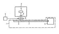
- Fig. 1 shows in a general form schematically a device according to the invention.
- a first unit (1) has here for example a linearly arranged light guide (3).
- the second unit (2) is arranged movably along this light guide.
- the first unit (1) comprises a light source (5), which couples optical signals into the light guide (3). These are guided along the light guide (3) and coupled at the position of the second unit (2) in this.
- the decoupling takes place by means of a coupler (4), which transmits the decoupled light into a light sink (6).
- This optical path from the light source (5) to the light sink (6) is shown as a dotted line (7).
- a variable optical attenuator (8) is provided in the optical path, which keeps the attenuation of the entire optical path at a constant value or in a predetermined tolerance range.
- the variable attenuator may optionally be associated with the first unit or the second unit.
- a control unit (9) is provided, which signals the attenuator the necessary damping setting.
Landscapes
- Physics & Mathematics (AREA)
- Electromagnetism (AREA)
- Engineering & Computer Science (AREA)
- Computer Networks & Wireless Communication (AREA)
- Signal Processing (AREA)
- General Physics & Mathematics (AREA)
- Optics & Photonics (AREA)
- Mechanical Light Control Or Optical Switches (AREA)
- Optical Communication System (AREA)
- Arrangements For Transmission Of Measured Signals (AREA)
Claims (9)
- Dispositif pour la transmission de signaux optiques entre au moins deux unités (1, 2) pouvant tourner l'une par rapport à l'autre, comprenant- une première unité (1), qui possède un guide d'ondes lumineuses (3) disposé le long de la trajectoire de déplacement, et- une deuxième unité (2), qui possède un coupleur (4) mobile le long du guide d'ondes lumineuses (3) pour le couplage et le découplage de signaux optiques dans et hors du guide d'ondes lumineuses (3), ainsi que- au moins une source de lumière (5) et- au moins un puits de lumière (6),- au moins un trajet optique (7) entre l'au moins une source de lumière (5) et l'au moins un puits de lumière (6), l'au moins une source de lumière et l'au moins un puits de lumière étant associés au choix à la première unité ou à la deuxième unité,caractérisé en ce qu'au moins un élément d'atténuation optique variable (8) est prévu dans l'au moins un trajet optique (7), ainsi qu'une unité de commande (9) qui règle l'au moins un élément d'atténuation optique (8) de telle manière que l'atténuation optique de l'au moins un trajet optique (7) se situe dans une plage de tolérances prédéterminée et l'unité de commande est conçue pour une commande en fonction de la position relative de la première unité par rapport à la deuxième unité, l'atténuation déterminée par les systèmes de mesure et de calcul en fonction de la distance étant utilisée pour la commande.
- Dispositif selon le préambule de la revendication 1, caractérisé en ce qu'au moins une source de lumière (5) comporte des moyens pour la commande électrique de la puissance optique délivrée et il est prévu une unité de commande (9) qui régule la puissance optique de la source de lumière de telle manière que la puissance optique à l'entrée du puits de lumière (6) du trajet optique associé se situe dans une plage de tolérance prédéterminée et l'unité de commande est conçue pour une commande en fonction de la position relative de la première unité par rapport à la deuxième unité, l'atténuation déterminée par les systèmes de mesure et de calcul en fonction de la distance étant utilisée pour la commande.
- Dispositif selon l'une des revendications précédentes, caractérisé en ce qu'au moins un puits de lumière (6) est conçu comme convertisseur de signaux optiques en signaux électriques et comporte des moyens de régulation électrique de la sensibilité électrique ou de l'amplification et il est en outre prévu une unité de commande (9) qui régule la sensibilité électrique ou l'amplification du puits de lumière de telle manière que l'amplitude des signaux électriques se situe dans une plage de tolérances prédéterminée et l'unité de commande est conçue pour une commande en fonction de la position relative de la première unité par rapport à la deuxième unité, l'atténuation déterminée par les systèmes de mesure et de calcul en fonction de la distance étant utilisée pour la commande.
- Dispositif selon la revendication 1, caractérisé en ce qu'au moins un élément d'atténuation optique variable (8) est conçu comme un milieu optiquement actif, dont l'atténuation change en fonction de l'intensité lumineuse incidente.
- Dispositif selon la revendication 1, caractérisé en ce qu'au moins un élément d'atténuation optique variable (8) est conçu comme un obturateur optique, tel qu'il est utilisé par exemple dans les objectifs des caméras.
- Dispositif selon la revendication 1, caractérisé en ce qu'au moins un élément d'atténuation optique variable (8) est conçu comme un coin neutre, qui est inséré dans le trajet des rayons en fonction de l'atténuation nécessaire.
- Dispositif selon la revendication 1, caractérisé en ce qu'au moins un élément d'atténuation optique variable (8) est conçu comme un élément biréfringent, par exemple comme un afficheur à cristaux liquides.
- Dispositif selon l'une des revendications 2 à 4, caractérisé en ce que l'unité de commande est intégrée par un couplage de rétroaction dans une boucle de régulation pour la régulation de la grandeur de sortie.
- Dispositif selon la revendication 2, caractérisé en ce que l'unité de commande présente un engrenage mécanique.
Applications Claiming Priority (3)
| Application Number | Priority Date | Filing Date | Title |
|---|---|---|---|
| DE10222221 | 2002-05-16 | ||
| DE10222221A DE10222221A1 (de) | 2002-05-16 | 2002-05-16 | Vorrichtung zur optischen Signalübertragung zwischen zwei gegeneinander beweglichen Einheiten |
| PCT/DE2003/001535 WO2003098846A1 (fr) | 2002-05-16 | 2003-05-13 | Dispositif pour transmettre des signaux optiques entre deux unites mobiles l'une par rapport a l'autre |
Publications (2)
| Publication Number | Publication Date |
|---|---|
| EP1504548A1 EP1504548A1 (fr) | 2005-02-09 |
| EP1504548B1 true EP1504548B1 (fr) | 2008-10-08 |
Family
ID=29432153
Family Applications (1)
| Application Number | Title | Priority Date | Filing Date |
|---|---|---|---|
| EP03735299A Expired - Lifetime EP1504548B1 (fr) | 2002-05-16 | 2003-05-13 | Dispositif pour transmettre des signaux optiques entre deux unites mobiles l'une par rapport a l'autre |
Country Status (6)
| Country | Link |
|---|---|
| US (1) | US7099532B2 (fr) |
| EP (1) | EP1504548B1 (fr) |
| AT (1) | ATE410843T1 (fr) |
| AU (1) | AU2003236792A1 (fr) |
| DE (3) | DE10222221A1 (fr) |
| WO (1) | WO2003098846A1 (fr) |
Families Citing this family (7)
| Publication number | Priority date | Publication date | Assignee | Title |
|---|---|---|---|---|
| DE10311325A1 (de) | 2003-03-14 | 2004-10-07 | Siemens Ag | Notfallbedienmittel für eine technische Einrichtung |
| DE102005010845A1 (de) * | 2004-12-15 | 2006-07-06 | Schleifring Und Apparatebau Gmbh | Optischer Drehübertrager mit aktiver Terminierung |
| EP2073406B1 (fr) | 2007-12-17 | 2014-02-12 | Siemens Aktiengesellschaft | Machine dotée d'une communication optique entre une première partie de machine et une seconde partie de machine pivotant en fonction de la première partie de machine |
| WO2015014983A1 (fr) * | 2013-08-01 | 2015-02-05 | Hirschmann Automation And Control Gmbh | Transmission optique de données par l'intermédiaire d'une bague collectrice d'une grue |
| CN104535089B (zh) * | 2014-12-15 | 2017-12-19 | 哈尔滨工程大学 | 一种具有光程可调功能的杨氏光纤白光干涉解调仪 |
| DE202017101776U1 (de) | 2017-03-28 | 2018-06-29 | Conductix-Wampfler Gmbh | Vorrichtung zur optischen Datenübertragung |
| US11858416B2 (en) * | 2022-05-03 | 2024-01-02 | GM Global Technology Operations LLC | Decorative light guide as high-speed optical interconnect |
Family Cites Families (19)
| Publication number | Priority date | Publication date | Assignee | Title |
|---|---|---|---|---|
| DE2301673C3 (de) * | 1972-01-27 | 1975-11-13 | Ponder & Best, Inc., Los Angeles, Calif. (V.St.A.) | Veränderbarer optischer Abschwächer |
| US4330870A (en) * | 1980-09-05 | 1982-05-18 | Datapoint Corporation | Optical data link |
| JPS58171137A (ja) * | 1982-04-01 | 1983-10-07 | Oki Electric Ind Co Ltd | 光減衰形agc方式 |
| JPS59110232A (ja) * | 1982-12-15 | 1984-06-26 | Fujitsu Ltd | 光受信信号制御装置 |
| JPS59111432A (ja) * | 1982-12-17 | 1984-06-27 | Nec Corp | 海底光通信方式 |
| US4525025A (en) * | 1983-03-21 | 1985-06-25 | Litton Systems Inc. | Fiber optic rotary joint using a reflective surface and tangentially mounted rotor and stator optical fibers |
| GB8531150D0 (en) * | 1985-12-18 | 1986-01-29 | Smiths Industries Plc | Optical multiplex systems |
| DE3805328A1 (de) * | 1988-02-20 | 1989-08-31 | Asea Brown Boveri | Verfahren zur messwertuebertragung bei einer lichtleiteruebertragung der messwerte |
| US5015057A (en) * | 1989-09-21 | 1991-05-14 | Tektronix, Inc. | Liquid crystal fiber optic attenuator and process for making same |
| US5297225A (en) * | 1992-06-04 | 1994-03-22 | Focal Technologies Incorporated | Off-axis optical rotary joint |
| US5506410A (en) * | 1994-05-16 | 1996-04-09 | Matsushita Electric Industrial Co., Ltd. | Cordless movable apparatus using optical spatial tranceivers |
| JPH10161076A (ja) * | 1996-11-29 | 1998-06-19 | Fujitsu Ltd | 磁気光学効果を利用した光デバイス |
| US6396613B1 (en) * | 1998-12-22 | 2002-05-28 | General Electric Company | Optical high speed communications for a computed tomography x-ray machine |
| US6075613A (en) * | 1999-02-26 | 2000-06-13 | General Scanning, Inc. | Optical scanner calibration device |
| DE19934498C2 (de) * | 1999-07-22 | 2001-11-29 | Siemens Ag | Schaltungsanordnung und Verfahren zum Erkennen von einer Unterbrechung einer Lichtwellenleiterstrecke |
| DE19950880C1 (de) * | 1999-10-22 | 2001-06-28 | Torsten Gogolla | Verfahren und Fasersensor zur Korrektur von im Zuge ortsausgelöster Messungen aufgenommenen Brillouin-Spektren |
| DE19956557B4 (de) * | 1999-11-24 | 2012-02-02 | Continental Automotive Gmbh | Sensor zur Durchführung eines Messverfahrens zur optischen Positionsbestimmung eines Bewegungsgliedes |
| US6943937B2 (en) * | 2001-05-17 | 2005-09-13 | Avanex Corporation | Optical amplifier performance controller and method of use |
| WO2003102677A1 (fr) * | 2002-05-28 | 2003-12-11 | Schleifring Und Apparatebau Gmbh | Dispositif de transmission optique de signaux entre deux unites qui sont deplacees l'une par rapport a l'autre |
-
2002
- 2002-05-16 DE DE10222221A patent/DE10222221A1/de not_active Withdrawn
-
2003
- 2003-05-13 EP EP03735299A patent/EP1504548B1/fr not_active Expired - Lifetime
- 2003-05-13 AT AT03735299T patent/ATE410843T1/de not_active IP Right Cessation
- 2003-05-13 DE DE10393083T patent/DE10393083D2/de not_active Withdrawn - After Issue
- 2003-05-13 DE DE50310612T patent/DE50310612D1/de not_active Expired - Fee Related
- 2003-05-13 WO PCT/DE2003/001535 patent/WO2003098846A1/fr not_active Ceased
- 2003-05-13 AU AU2003236792A patent/AU2003236792A1/en not_active Abandoned
-
2004
- 2004-11-15 US US10/989,233 patent/US7099532B2/en not_active Expired - Fee Related
Also Published As
| Publication number | Publication date |
|---|---|
| DE10393083D2 (de) | 2005-05-12 |
| US7099532B2 (en) | 2006-08-29 |
| DE50310612D1 (de) | 2008-11-20 |
| US20050116154A1 (en) | 2005-06-02 |
| DE10222221A1 (de) | 2004-03-04 |
| ATE410843T1 (de) | 2008-10-15 |
| WO2003098846A1 (fr) | 2003-11-27 |
| WO2003098846B1 (fr) | 2004-03-04 |
| AU2003236792A1 (en) | 2003-12-02 |
| EP1504548A1 (fr) | 2005-02-09 |
Similar Documents
| Publication | Publication Date | Title |
|---|---|---|
| DE3223898C2 (de) | Einstellbares optisches Dämpfungsglied | |
| DE102007004514A1 (de) | Zweikanal Multimode Drehübertager | |
| DE69713740T2 (de) | Optische vorrichtung | |
| EP1504548B1 (fr) | Dispositif pour transmettre des signaux optiques entre deux unites mobiles l'une par rapport a l'autre | |
| EP1399771A2 (fr) | Dispositif d'eclairage plat d'un champ d'objet | |
| DE69829896T2 (de) | Lichtquelle mit variabler Wellenlänge und OTDR Apparat | |
| WO2001095000A2 (fr) | Systeme optique de transfert de donnees | |
| DE10160218A1 (de) | Vorrichtung zur gesteuerten Übertragung optischer Signale in Lichtleitern | |
| DE10160233B4 (de) | Vorrichtung zur Übertragung optischer Signale unter seitlicher Ankopplung an Lichtwellenleiter | |
| WO2010040726A1 (fr) | Multiplexeur/demultiplexeur compact | |
| DE10014644A1 (de) | Optisches Modul zur Wellenlängen-Referenzmessung in WDM-Systemen | |
| EP1166474B1 (fr) | Procede permettant, au moyen de cristaux photoniques, de compenser la dispersion de signaux optiques de differentes longueurs d'onde transmis ensemble | |
| EP1512042B1 (fr) | Dispositif de transmission optique de signaux entre deux unites qui sont deplacees l'une par rapport a l'autre | |
| EP0073314B1 (fr) | Système de transmission pour une utilisation multiple bidirectionnelle d'une fibre optique | |
| WO2008077624A1 (fr) | Transformateur de rotation optique avec un affaiblissement de retour élevé | |
| DE10240228B4 (de) | Vorrichtung zur optischen Signalübertragung zwischen zwei gegeneinander beweglichen Einheiten | |
| EP1312940A1 (fr) | Barrière optique avec guide d'ondes optiques | |
| DE102005010557A1 (de) | Optischer Multiplexer/Demultiplexer | |
| EP3069179B1 (fr) | Système de bague collectrice optique | |
| EP1672400B1 (fr) | Joint optique tournant | |
| DE2918528A1 (de) | Optisches daempfungsglied | |
| DE102008027314A1 (de) | Verfahren und Vorrichtung zur Ankopplung eines Lichtwellenleiters an eine Licht ermittierende oder Licht führende Komponente | |
| DD157633A1 (de) | Optisches daempfungsglied | |
| DD214219A1 (de) | Einrichtung zur beeinflussung der lichtausbreitung | |
| DE3312170A1 (de) | Optisches daempfungsglied |
Legal Events
| Date | Code | Title | Description |
|---|---|---|---|
| PUAI | Public reference made under article 153(3) epc to a published international application that has entered the european phase |
Free format text: ORIGINAL CODE: 0009012 |
|
| 17P | Request for examination filed |
Effective date: 20041030 |
|
| AK | Designated contracting states |
Kind code of ref document: A1 Designated state(s): AT BE BG CH CY CZ DE DK EE ES FI FR GB GR HU IE IT LI LU MC NL PT RO SE SI SK TR |
|
| AX | Request for extension of the european patent |
Extension state: AL LT LV MK |
|
| DAX | Request for extension of the european patent (deleted) | ||
| GRAP | Despatch of communication of intention to grant a patent |
Free format text: ORIGINAL CODE: EPIDOSNIGR1 |
|
| GRAC | Information related to communication of intention to grant a patent modified |
Free format text: ORIGINAL CODE: EPIDOSCIGR1 |
|
| GRAS | Grant fee paid |
Free format text: ORIGINAL CODE: EPIDOSNIGR3 |
|
| GRAA | (expected) grant |
Free format text: ORIGINAL CODE: 0009210 |
|
| AK | Designated contracting states |
Kind code of ref document: B1 Designated state(s): AT BE BG CH CY CZ DE DK EE ES FI FR GB GR HU IE IT LI LU MC NL PT RO SE SI SK TR |
|
| REG | Reference to a national code |
Ref country code: GB Ref legal event code: FG4D Free format text: NOT ENGLISH |
|
| REG | Reference to a national code |
Ref country code: CH Ref legal event code: EP |
|
| REG | Reference to a national code |
Ref country code: IE Ref legal event code: FG4D Free format text: LANGUAGE OF EP DOCUMENT: GERMAN |
|
| REF | Corresponds to: |
Ref document number: 50310612 Country of ref document: DE Date of ref document: 20081120 Kind code of ref document: P |
|
| PG25 | Lapsed in a contracting state [announced via postgrant information from national office to epo] |
Ref country code: SI Free format text: LAPSE BECAUSE OF FAILURE TO SUBMIT A TRANSLATION OF THE DESCRIPTION OR TO PAY THE FEE WITHIN THE PRESCRIBED TIME-LIMIT Effective date: 20081008 |
|
| NLV1 | Nl: lapsed or annulled due to failure to fulfill the requirements of art. 29p and 29m of the patents act | ||
| PG25 | Lapsed in a contracting state [announced via postgrant information from national office to epo] |
Ref country code: ES Free format text: LAPSE BECAUSE OF FAILURE TO SUBMIT A TRANSLATION OF THE DESCRIPTION OR TO PAY THE FEE WITHIN THE PRESCRIBED TIME-LIMIT Effective date: 20090119 Ref country code: BG Free format text: LAPSE BECAUSE OF FAILURE TO SUBMIT A TRANSLATION OF THE DESCRIPTION OR TO PAY THE FEE WITHIN THE PRESCRIBED TIME-LIMIT Effective date: 20090108 |
|
| PG25 | Lapsed in a contracting state [announced via postgrant information from national office to epo] |
Ref country code: FI Free format text: LAPSE BECAUSE OF FAILURE TO SUBMIT A TRANSLATION OF THE DESCRIPTION OR TO PAY THE FEE WITHIN THE PRESCRIBED TIME-LIMIT Effective date: 20081008 Ref country code: NL Free format text: LAPSE BECAUSE OF FAILURE TO SUBMIT A TRANSLATION OF THE DESCRIPTION OR TO PAY THE FEE WITHIN THE PRESCRIBED TIME-LIMIT Effective date: 20081008 Ref country code: PT Free format text: LAPSE BECAUSE OF FAILURE TO SUBMIT A TRANSLATION OF THE DESCRIPTION OR TO PAY THE FEE WITHIN THE PRESCRIBED TIME-LIMIT Effective date: 20090218 |
|
| REG | Reference to a national code |
Ref country code: IE Ref legal event code: FD4D |
|
| PG25 | Lapsed in a contracting state [announced via postgrant information from national office to epo] |
Ref country code: IE Free format text: LAPSE BECAUSE OF FAILURE TO SUBMIT A TRANSLATION OF THE DESCRIPTION OR TO PAY THE FEE WITHIN THE PRESCRIBED TIME-LIMIT Effective date: 20081008 Ref country code: EE Free format text: LAPSE BECAUSE OF FAILURE TO SUBMIT A TRANSLATION OF THE DESCRIPTION OR TO PAY THE FEE WITHIN THE PRESCRIBED TIME-LIMIT Effective date: 20081008 Ref country code: RO Free format text: LAPSE BECAUSE OF FAILURE TO SUBMIT A TRANSLATION OF THE DESCRIPTION OR TO PAY THE FEE WITHIN THE PRESCRIBED TIME-LIMIT Effective date: 20081008 Ref country code: DK Free format text: LAPSE BECAUSE OF FAILURE TO SUBMIT A TRANSLATION OF THE DESCRIPTION OR TO PAY THE FEE WITHIN THE PRESCRIBED TIME-LIMIT Effective date: 20081008 |
|
| PLBE | No opposition filed within time limit |
Free format text: ORIGINAL CODE: 0009261 |
|
| STAA | Information on the status of an ep patent application or granted ep patent |
Free format text: STATUS: NO OPPOSITION FILED WITHIN TIME LIMIT |
|
| PG25 | Lapsed in a contracting state [announced via postgrant information from national office to epo] |
Ref country code: CZ Free format text: LAPSE BECAUSE OF FAILURE TO SUBMIT A TRANSLATION OF THE DESCRIPTION OR TO PAY THE FEE WITHIN THE PRESCRIBED TIME-LIMIT Effective date: 20081008 Ref country code: IT Free format text: LAPSE BECAUSE OF FAILURE TO SUBMIT A TRANSLATION OF THE DESCRIPTION OR TO PAY THE FEE WITHIN THE PRESCRIBED TIME-LIMIT Effective date: 20081008 Ref country code: SE Free format text: LAPSE BECAUSE OF FAILURE TO SUBMIT A TRANSLATION OF THE DESCRIPTION OR TO PAY THE FEE WITHIN THE PRESCRIBED TIME-LIMIT Effective date: 20090108 |
|
| PGFP | Annual fee paid to national office [announced via postgrant information from national office to epo] |
Ref country code: DE Payment date: 20090526 Year of fee payment: 7 Ref country code: FR Payment date: 20090527 Year of fee payment: 7 |
|
| 26N | No opposition filed |
Effective date: 20090709 |
|
| PG25 | Lapsed in a contracting state [announced via postgrant information from national office to epo] |
Ref country code: SK Free format text: LAPSE BECAUSE OF FAILURE TO SUBMIT A TRANSLATION OF THE DESCRIPTION OR TO PAY THE FEE WITHIN THE PRESCRIBED TIME-LIMIT Effective date: 20081008 |
|
| BERE | Be: lapsed |
Owner name: SCHLEIFRING UND APPARATEBAU G.M.B.H. Effective date: 20090531 |
|
| PGFP | Annual fee paid to national office [announced via postgrant information from national office to epo] |
Ref country code: GB Payment date: 20090527 Year of fee payment: 7 |
|
| PG25 | Lapsed in a contracting state [announced via postgrant information from national office to epo] |
Ref country code: MC Free format text: LAPSE BECAUSE OF NON-PAYMENT OF DUE FEES Effective date: 20090531 |
|
| REG | Reference to a national code |
Ref country code: CH Ref legal event code: PL |
|
| PG25 | Lapsed in a contracting state [announced via postgrant information from national office to epo] |
Ref country code: CH Free format text: LAPSE BECAUSE OF NON-PAYMENT OF DUE FEES Effective date: 20090531 Ref country code: LI Free format text: LAPSE BECAUSE OF NON-PAYMENT OF DUE FEES Effective date: 20090531 |
|
| PG25 | Lapsed in a contracting state [announced via postgrant information from national office to epo] |
Ref country code: BE Free format text: LAPSE BECAUSE OF NON-PAYMENT OF DUE FEES Effective date: 20090531 |
|
| PG25 | Lapsed in a contracting state [announced via postgrant information from national office to epo] |
Ref country code: AT Free format text: LAPSE BECAUSE OF NON-PAYMENT OF DUE FEES Effective date: 20090513 |
|
| PG25 | Lapsed in a contracting state [announced via postgrant information from national office to epo] |
Ref country code: GR Free format text: LAPSE BECAUSE OF FAILURE TO SUBMIT A TRANSLATION OF THE DESCRIPTION OR TO PAY THE FEE WITHIN THE PRESCRIBED TIME-LIMIT Effective date: 20090109 |
|
| GBPC | Gb: european patent ceased through non-payment of renewal fee |
Effective date: 20100513 |
|
| REG | Reference to a national code |
Ref country code: FR Ref legal event code: ST Effective date: 20110131 |
|
| PG25 | Lapsed in a contracting state [announced via postgrant information from national office to epo] |
Ref country code: DE Free format text: LAPSE BECAUSE OF NON-PAYMENT OF DUE FEES Effective date: 20101201 Ref country code: LU Free format text: LAPSE BECAUSE OF NON-PAYMENT OF DUE FEES Effective date: 20090513 |
|
| PG25 | Lapsed in a contracting state [announced via postgrant information from national office to epo] |
Ref country code: FR Free format text: LAPSE BECAUSE OF NON-PAYMENT OF DUE FEES Effective date: 20100531 |
|
| PG25 | Lapsed in a contracting state [announced via postgrant information from national office to epo] |
Ref country code: HU Free format text: LAPSE BECAUSE OF FAILURE TO SUBMIT A TRANSLATION OF THE DESCRIPTION OR TO PAY THE FEE WITHIN THE PRESCRIBED TIME-LIMIT Effective date: 20090409 |
|
| PG25 | Lapsed in a contracting state [announced via postgrant information from national office to epo] |
Ref country code: GB Free format text: LAPSE BECAUSE OF NON-PAYMENT OF DUE FEES Effective date: 20100513 |
|
| PG25 | Lapsed in a contracting state [announced via postgrant information from national office to epo] |
Ref country code: TR Free format text: LAPSE BECAUSE OF FAILURE TO SUBMIT A TRANSLATION OF THE DESCRIPTION OR TO PAY THE FEE WITHIN THE PRESCRIBED TIME-LIMIT Effective date: 20081008 |
|
| PG25 | Lapsed in a contracting state [announced via postgrant information from national office to epo] |
Ref country code: CY Free format text: LAPSE BECAUSE OF FAILURE TO SUBMIT A TRANSLATION OF THE DESCRIPTION OR TO PAY THE FEE WITHIN THE PRESCRIBED TIME-LIMIT Effective date: 20081008 |