EP1505268B1 - Brennkraftmaschine mit Ventilverstelleinrichtung zentral auf der Nockenwelle montiert - Google Patents
Brennkraftmaschine mit Ventilverstelleinrichtung zentral auf der Nockenwelle montiert Download PDFInfo
- Publication number
- EP1505268B1 EP1505268B1 EP04018490A EP04018490A EP1505268B1 EP 1505268 B1 EP1505268 B1 EP 1505268B1 EP 04018490 A EP04018490 A EP 04018490A EP 04018490 A EP04018490 A EP 04018490A EP 1505268 B1 EP1505268 B1 EP 1505268B1
- Authority
- EP
- European Patent Office
- Prior art keywords
- camshaft
- flange
- valve timing
- timing controller
- internal rotor
- Prior art date
- Legal status (The legal status is an assumption and is not a legal conclusion. Google has not performed a legal analysis and makes no representation as to the accuracy of the status listed.)
- Expired - Lifetime
Links
- 238000002485 combustion reaction Methods 0.000 description 5
- 230000003247 decreasing effect Effects 0.000 description 4
- 230000000694 effects Effects 0.000 description 4
- 230000002829 reductive effect Effects 0.000 description 4
- 230000009286 beneficial effect Effects 0.000 description 2
- 239000000314 lubricant Substances 0.000 description 2
- 230000000979 retarding effect Effects 0.000 description 2
- 238000005553 drilling Methods 0.000 description 1
- 239000011347 resin Substances 0.000 description 1
- 229920005989 resin Polymers 0.000 description 1
- 230000000717 retained effect Effects 0.000 description 1
- 230000002441 reversible effect Effects 0.000 description 1
- 238000004804 winding Methods 0.000 description 1
Images


Classifications
-
- F—MECHANICAL ENGINEERING; LIGHTING; HEATING; WEAPONS; BLASTING
- F01—MACHINES OR ENGINES IN GENERAL; ENGINE PLANTS IN GENERAL; STEAM ENGINES
- F01L—CYCLICALLY OPERATING VALVES FOR MACHINES OR ENGINES
- F01L1/00—Valve-gear or valve arrangements, e.g. lift-valve gear
- F01L1/34—Valve-gear or valve arrangements, e.g. lift-valve gear characterised by the provision of means for changing the timing of the valves without changing the duration of opening and without affecting the magnitude of the valve lift
- F01L1/344—Valve-gear or valve arrangements, e.g. lift-valve gear characterised by the provision of means for changing the timing of the valves without changing the duration of opening and without affecting the magnitude of the valve lift changing the angular relationship between crankshaft and camshaft, e.g. using helicoidal gear
- F01L1/3442—Valve-gear or valve arrangements, e.g. lift-valve gear characterised by the provision of means for changing the timing of the valves without changing the duration of opening and without affecting the magnitude of the valve lift changing the angular relationship between crankshaft and camshaft, e.g. using helicoidal gear using hydraulic chambers with variable volume to transmit the rotating force
-
- F—MECHANICAL ENGINEERING; LIGHTING; HEATING; WEAPONS; BLASTING
- F01—MACHINES OR ENGINES IN GENERAL; ENGINE PLANTS IN GENERAL; STEAM ENGINES
- F01L—CYCLICALLY OPERATING VALVES FOR MACHINES OR ENGINES
- F01L1/00—Valve-gear or valve arrangements, e.g. lift-valve gear
- F01L1/02—Valve drive
- F01L1/022—Chain drive
-
- F—MECHANICAL ENGINEERING; LIGHTING; HEATING; WEAPONS; BLASTING
- F01—MACHINES OR ENGINES IN GENERAL; ENGINE PLANTS IN GENERAL; STEAM ENGINES
- F01L—CYCLICALLY OPERATING VALVES FOR MACHINES OR ENGINES
- F01L1/00—Valve-gear or valve arrangements, e.g. lift-valve gear
- F01L1/02—Valve drive
- F01L1/024—Belt drive
-
- F—MECHANICAL ENGINEERING; LIGHTING; HEATING; WEAPONS; BLASTING
- F01—MACHINES OR ENGINES IN GENERAL; ENGINE PLANTS IN GENERAL; STEAM ENGINES
- F01L—CYCLICALLY OPERATING VALVES FOR MACHINES OR ENGINES
- F01L1/00—Valve-gear or valve arrangements, e.g. lift-valve gear
- F01L1/02—Valve drive
- F01L1/04—Valve drive by means of cams, camshafts, cam discs, eccentrics or the like
- F01L1/047—Camshafts
- F01L1/053—Camshafts overhead type
- F01L1/0532—Camshafts overhead type the cams being directly in contact with the driven valve
-
- F—MECHANICAL ENGINEERING; LIGHTING; HEATING; WEAPONS; BLASTING
- F01—MACHINES OR ENGINES IN GENERAL; ENGINE PLANTS IN GENERAL; STEAM ENGINES
- F01L—CYCLICALLY OPERATING VALVES FOR MACHINES OR ENGINES
- F01L1/00—Valve-gear or valve arrangements, e.g. lift-valve gear
- F01L1/02—Valve drive
- F01L1/026—Gear drive
-
- F—MECHANICAL ENGINEERING; LIGHTING; HEATING; WEAPONS; BLASTING
- F01—MACHINES OR ENGINES IN GENERAL; ENGINE PLANTS IN GENERAL; STEAM ENGINES
- F01L—CYCLICALLY OPERATING VALVES FOR MACHINES OR ENGINES
- F01L1/00—Valve-gear or valve arrangements, e.g. lift-valve gear
- F01L1/02—Valve drive
- F01L1/04—Valve drive by means of cams, camshafts, cam discs, eccentrics or the like
- F01L1/047—Camshafts
- F01L1/053—Camshafts overhead type
- F01L2001/0537—Double overhead camshafts [DOHC]
-
- F—MECHANICAL ENGINEERING; LIGHTING; HEATING; WEAPONS; BLASTING
- F01—MACHINES OR ENGINES IN GENERAL; ENGINE PLANTS IN GENERAL; STEAM ENGINES
- F01L—CYCLICALLY OPERATING VALVES FOR MACHINES OR ENGINES
- F01L1/00—Valve-gear or valve arrangements, e.g. lift-valve gear
- F01L1/34—Valve-gear or valve arrangements, e.g. lift-valve gear characterised by the provision of means for changing the timing of the valves without changing the duration of opening and without affecting the magnitude of the valve lift
- F01L1/344—Valve-gear or valve arrangements, e.g. lift-valve gear characterised by the provision of means for changing the timing of the valves without changing the duration of opening and without affecting the magnitude of the valve lift changing the angular relationship between crankshaft and camshaft, e.g. using helicoidal gear
- F01L1/3442—Valve-gear or valve arrangements, e.g. lift-valve gear characterised by the provision of means for changing the timing of the valves without changing the duration of opening and without affecting the magnitude of the valve lift changing the angular relationship between crankshaft and camshaft, e.g. using helicoidal gear using hydraulic chambers with variable volume to transmit the rotating force
- F01L2001/34423—Details relating to the hydraulic feeding circuit
- F01L2001/34426—Oil control valves
- F01L2001/3443—Solenoid driven oil control valves
Definitions
- This invention relates to an engine according to the preamble part of the independent claim 1, and particularly, to a mounting structure of a valve timing controller for engine for controlling timing to open/close valves.
- valve timing controllers One of the conventional type valve timing controllers is described in JP-A-H11-022426 . This document discloses the valve timing controller with the following structure.
- a camshaft is rotatably supported by a cylinder head in an internal combustion chamber.
- An internal rotor is provided at a tip end of the camshaft.
- Rotation transmitting members are also provided, including an external rotor, fitted on the outside of the internal rotor with the camshaft for relative rotation within a given range: a front plate; a cap: a rear plate and a timing sprocket.
- Six vanes attached to the internal rotor and a lock mechanism attached to the external rotor also constitute the valve opening/closing timing controller.
- timing sprocket receives rotational power transmitted from a crank sprocket through a resin or rubber timing belt in a given direction.
- the camshaft has well-known cams for opening/closing intake valves. Inside of the camshaft, a timing-advance path and a timing-retard path are provided, which extend in the axial direction of the camshaft. These paths are connected to their respective connection ports of a directional control valve.
- the directional control valve allows a spool to move against urging force of a spring by energizing a solenoid.
- an oil delivery port connected to an oil pump driven by the internal combustion chamber is communicated with one of the connection ports while the other connection port is communicated with an oil drain port.
- moving the spool allows the oil delivery port to be communicated with the aforementioned other connection port, while allowing the aforementioned one connection port to be communicated with the oil drain port.
- the internal rotor and the external rotor relatively rotate by a given angle between when the solenoid is energized and when the solenoid is not energized, thereby changing the phases of the crankshaft and the camshaft to control the opening/closing timing of the intake valves.
- an engine having a valve timing controller, wherein a camshaft is provided with a mounting structure for the valve timing controller comprising a boss and a flange adjacent to the boss and radially protruding, wherein the valve timing controller is mounted to the flange with the boss fitted into a through hole, wherein the through hole of the valve timing controller is provided in a center thereof and has a circular shape, with a diameter slightly larger than a value equivalent to a sum of a radius of a base circle of a cam and a height of a cam nose of the camshaft.
- valve timing controller is provided around the camshaft for changing phases of relation between a crankshaft and the camshaft.
- valve timing controller has an internal rotor provided on the camshaft and an external rotor provided rotatably around the internal rotor, that the external rotor is provided with a driven section to which driving force from the crankshaft is inputted, and that the internal rotor is formed with the through hole while being mounted to the flange.
- the internal rotor has a female thread
- the flange has a through hole with male thread, in order for the internal rotor to be fixed from the flange side with a mounting bolt.
- valve timing controller is provided on at least one of the camshafts in pairs, and the external rotor of the valve timing controller is provided with a camshaft driving section for driving the other camshaft.
- camshaft driving section has an outside diameter smaller than that of the driven section.
- the external rotor is arranged so as to slide on the internal rotor provided around the outer periphery of the boss, and the camshaft driving section, formed as a separate body from the external rotor, is slidably mounted to the flange, wherein a clearance between the camshaft driving section and the flange is designed smaller than the one between the internal rotor and the external rotor.
- the external rotor may be arranged so as to slide on the internal rotor provided around the outer periphery of the boss, and the camshaft driving section, formed integral with the external rotor as a single unit, might be slidably mounted to the flange, wherein a clearance between the camshaft driving section and the flange is designed smaller than the one between the internal rotor and the external rotor.
- a position of the mounting bolt is arranged at a position out of phase of the cam nose in the circumferential direction of the camshaft.
- FIGs. 1 through 6 show the first embodiment.
- An engine of the first embodiment which is mounted to a motorcycle, is a four-valve two-cylinder four-stroke engine.
- This engine provided with a valve timing controller, is disposed with its crankshaft (not shown) arranged along a vehicle width direction.
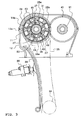
- FIG. 1 is a sectional view showing an upper side of the engine (intake side of a cylinder head), in which a reference numeral 11 denotes an intake-side camshaft, which is provided along the vehicle width direction.
- a reference numeral 11 denotes an intake-side camshaft, which is provided along the vehicle width direction.
- Cam caps 13 are secured to a cylinder head 12 with bolts 20 shown in FIG. 5 so that the camshaft 11 is rotatably supported by journals 14, 15, 16, 17 which are formed on the cam caps as shown in FIG. 1.
- the camshaft 11 has plural cams 11 a formed to push each of four intake valves 18 down against urging force of springs 19 in order to open their respective intake ports at a predetermined timing.
- the cylinder head 12 is secured to a cylinder block (not shown) with stud bolts 21 and nuts 22 provided for the adjacent journals 15, 16 while a head cover 24 is attached to the cam caps 13 through screws 23.
- a periphery 24a of the head cover 24 and an upper periphery 12a of the cylinder head 12 are sealed via a gasket 25.
- the camshaft 11 has a valve timing controller disposed between two cylinders A, B.
- the camshaft 11 has a boss 11b formed at its approximately middle section in the vehicle width direction, and a flange 11c with a predetermined diameter, radially protruding from a position adjacent to and the right of the boss 11b in FIG. 1.
- a ring-shaped internal rotor 26 of the valve timing controller is provided on the outer periphery of the boss 11b of the camshaft 11.
- the internal rotor 26 has a perfect circular through hole 26f with no cut at the center point, or the middle of the valve timing controller.
- the through hole 26f has a diameter slightly larger than a value, L1 (a radius of a base circle 11n of the cam 11a) + L2 (a height of a cam nose 11p). More specifically, the through hole 26f may have a diameter in a range between the value, L1 + L2, and a value, 2*L2, for example.
- a chain double-dashed line (a) shows the cam 11 a wholly arranged within the through hole 26f for comparison purpose, and in contrast to that, a dashed line (b) shows a tip end of the cam nose 11p extending off the through hole 26f when viewed in the axial direction, with the through hole 26f fitted through the boss 11b.
- the through hole 26f has a diameter large enough to be fitted through the outside of the boss 11 b with the boss 11 b fitted into the through hole 26f.
- each female thread 26a formed in the axial direction On an end face on the flange 11c side of the internal rotor 26, three female threads 26a formed in the axial direction are individually provided.
- a section corresponding to each female thread 26a on the flange 11c has a through hole 11m with male thread.
- a position of the through hole 11m with male thread on the flange 11c is arranged at a position out of phase of the cam nose 11p in the circumferential direction of the camshaft 11.
- the internal rotor 26 is tightly secured to the side face on the boss 11 side of the flange 11c with three mounting bolts 27 extending in the direction parallel to the axis of the camshaft 11. These mounting bolts 27 are inserted to the through hole 11 m with male thread from the flange 11c side with a male thread 27a engaged with the female thread 26a of the inner rotor 26 and with a head fitted into a recess 11d of the flange 11c, formed in the through hole 11 m with male thread.
- An approximately ring-shaped external rotor 28 is provided on the outside of the internal rotor 26 for relative rotation about the axis of the camshaft 11 with a clearance allowing the external rotor to slide on the outer periphery of the internal rotor 26.
- an intake-side gear member 31 as a camshaft driving section is mounted for relative rotation about the axis of the camshaft 11 with a clearance allowing the intake-side gear member 31 to slide on the outer periphery of the flange 11c.
- This clearance is designed smaller than the one between the external rotor 28 and the internal rotor 26.
- a shield plate 32 is provided, which is fastened together with the intake-side gear member 31 by means of a common bolt 33. Both side surfaces of the internal rotor 26 are slidably sandwiched between the intake-side gear member 31 and the shield plate 32.
- the external rotor 28, the intake-side gear member 31 and the shield plate 32 are integrally arranged for relative rotation about the internal rotor 26 by a predetermined angle.
- the external rotor 28 has a sprocket 28a as a driven section formed around its periphery.
- the sprocket 28a has a diameter larger than that of the intake-side gear member 31.
- a timing chain 35 is installed on the sprocket 28a and a crank sprocket 34 provided on the crankshaft side.
- the timing chain 35 has a fixed chain guide 37 provided on one side, and a movable chain guide 38 provided on the other side.
- the movable chain guide 38 is moved by a chain tensioner 39 to adjust its tension to a predetermined value.
- the intake-side gear member 31 engages with the exhaust-side gear member 41 of the same size diameter as the intake-side gear member as shown in FIGs. 2 and 3.
- An exhaust-side camshaft 91 rotates in synchronization with rotation of the exhaust-side gear member 41.
- the exhaust-side camshaft 91 has cams 91 a for opening and closing exhaust valves 93, as well as the exhaust-side gear member 41 and a scissors gear 42 mounted to an intermediate section in the longitudinal direction of this camshaft.
- the exhaust-side gear member 41 and the scissors gear 42 are mounted to the aforementioned camshaft with a stepped bolt 40.
- the exhaust-side gear member 41 has a chamfered section 41 a for preventing interference with the external rotor 28.
- the external rotor 28 has total eight recess sections 28b as shown in FIGs. 3 and 4. There are total eight hydraulic chambers 43 formed between these recess sections 28b and an outer periphery 26b of the internal rotor 26. Each hydraulic chamber 43 is divided into a timing-advance-side hydraulic chamber 44 and a timing-retard-side hydraulic chamber 45 by a vane 46.
- the vane 46 has a base end 46a retained in a retaining slot 26c formed into the internal rotor 26.
- the vane is disposed so as to freely extend and retract in a radial direction of the internal rotor 26 while being urged toward the outside by an unillustrated spring disposed within the retaining slot 26c. A tip end 46b of the vane 46 therefore comes into contact with a bottom wall 28c of the recess section 28b of the external rotor 28.
- a timing-advance-side oil path 48 communicating with the timing-advance-side hydraulic chamber 44 to deliver/drain oil, and a timing-retard-side oil path 49 communicating with the timing-retard-side hydraulic chamber 45 to deliver/drain oil are formed.
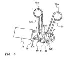
- the timing-advance-side oil path 48 has: a timing-advance path 31 a formed in the intake-side gear member 31 and facing the timing-advance-side hydraulic chamber 44; a timing-advance path 11e formed in the flange 11c of the camshaft 11 to communicate with the timing-advance path 31a; a timing-advance path 11f formed along the axial direction of the camshaft 11 to communicate with the timing-advance path 11e; a timing-advance path 11g formed on the camshaft 11 to communicated with the timing-advance path 11f; and a timing-advance path 16a formed in the journal 16 to communicate with the timing-advance path 11g. Furthermore, as shown in FIGs. 5 and 6, the timing-advance path 16a is communicated with a timing-advance path 12b formed extending outward of the cylinder head 12, which is connected to a directional
- the timing-retard-side oil path 49 has: a timing-retard path 26d formed in the internal rotor 26 and facing the timing-retard-side hydraulic chamber 45; a timing-retard path 11 h formed in the boss 11 b of the camshaft 11 to communicate with the timing-retard path 26d; a timing-retard path 11i formed along the axial direction of the camshaft 11 to communicate with the timing-retard path 11h; a timing-retard path 11j formed on the camshaft 11 to communicated with the timing-retard path 11i; and a timing-retard path 15a formed in the journal 15 to communicated with the timing-retard path 11j. Furthermore, as shown in FIGs. 5 and 6, the timing-retard path 15a is communicated with a timing-retard path 12c formed on the cylinder head 12, which is connected to a directional control valve 76.
- timing-advance path 11f and the timing-retard path 11i which are formed in the axial direction of the camshaft 11, are separately provided on the right and left sides relative to the layout position of the internal rotor 26 and the external rotor 28 on the common axis of the camshaft 11.
- These timing-advance path 11f and timing-retard path 11i are formed by drilling a hole to the midsection of the camshaft 11 from its both ends and disposing their respective lids 77 thereto. If a pair of left and right paths, used as the timing-advance path 11f and the timing-retard path 11i, have different longitudinal dimensions, one of the paths with a shorter dimension would be used as the timing-advance path 11f.
- the directional control valve 76 is configured such that a solenoid 79 causes a spool 80 to move forward and backward in the left and right direction in FIG. 6.
- the spool 80 is moved to a position shown by a chain double-dashed line in FIG. 6. Therefore, an oil delivery hole 81, to which oil is delivered from an oil pump driven by the engine, is communicated with the timing-advance path 12b of the timing-advance-side oil path 48. This allows the oil to be delivered to the timing-advance-side oil path 48.
- the timing-retard path 12c of the timing-retard-side oil path 49 is communicated with a drain opening 12d.
- the oil in the timing-retard-side hydraulic chamber 45 is drained out into the cylinder head 12 from the drain opening 12d.
- the drain opening 12d is positioned higher than a bottom edge of the camshaft 11 at the journals 14, 15, 16, 17 as shown in FIG. 5.
- a reference symbol O in FIG. 5 denotes a horizontal line.
- the spool 80 is further moved to a position shown by a solid line in FIG. 6. Therefore, the oil delivery hole 81 is communicated with the timing-retard path 12c of the timing-retard-side oil path 49 to which oil is delivered. In turn, the timing-advance path 12b of the timing-advance oil path 48 is communicated with the drain opening 12d. As shown by the arrow of solid line in FIG. 6, the oil in the timing-advance-side hydraulic chamber 44 is drained out into the cylinder head 12 from the drain opening 12d.
- the shield plate 32 mounted to the external rotor 28 shields the side of the retaining slot 26c of the internal rotor 26 in order to prevent the oil from leaking from a side opening of the retaining slot 26c.
- a stopper pin 83 for locking/unlocking relative rotation of the internal rotor 26 and the external rotor 28 is provided movably in the left and right direction in FIG. 1.
- the stopper pin 83 is subject to hydraulic pressure by the oil in the timing-advance-side oil path 48 delivered through a communication passage 26e shown in FIG. 4, and then moved toward the right in FIG. 1 against the urging force of the unillustrated spring. This allows an engaging projection 83a of the stopper pin 83 to be disengaged from an engaging hole 32a of the shield plate 32, thereby unlocking the internal rotor 26 and the external rotor 28.
- Each cam cap 13 is formed with an oil path 13a for the journals 14, 17, except the journals 15, 16 adjacent to the internal rotor 26. Oil is delivered to the journals 14, 17 through this oil path 13a and used as lubricant oil.
- the solenoid 79 moves the spool 80 to a position shown in the chain double-dashed line in FIG. 6. This allows the oil to be delivered to the timing-advance-side hydraulic chamber 44 through the timing-advance-side oil path 48, while allowing the oil in the timing-retard-side hydraulic chamber 45 to be drained out from the drain opening 12d through the timing-retard-side oil path 49.
- the oil is delivered to the timing-advance-side oil path 48 and then to the stopper pin 83.
- the engaging projection 83a of the stopper pin 83 is therefore disengaged from the engaging hole 32a of the shield plate 32, resulting in the internal rotor 26 and the external rotor 28 being unlocked from each other.
- each vane 46 in the hydraulic chamber 43 moves to a position shown by the chain double-dashed line in FIG. 4, which increases the capacity of the timing-advance-side hydraulic chamber 44 while decreasing the capacity of the timing-retard-side hydraulic chamber 45.
- the solenoid 79 moves the spool 80 to a position shown in the solid line in FIG. 6. This allows the oil in the timing-retard-side hydraulic chamber 45 to be delivered through the timing-retard-side oil path 49, while allowing the oil in the timing-advance-side hydraulic chamber 44 to be drained out from the drain opening 12d through the timing-advance-side oil path 48.
- each vane 46 in the hydraulic chamber 43 moves to a position shown by the solid line in FIG. 4, which increases the capacity of the timing-retard-side hydraulic chamber 45 while decreasing the capacity of the timing-advance-side hydraulic chamber 44.
- Advancing or retarding the valve timing as described above allows the intake valves 18 to be open/closed at a predetermined timing.
- the valve timing controller has a given through hole 26f in its center to be fixed to the flange 11c with the through hole 26f fitted through the boss 11 b of the camshaft 11. This allows the valve timing controller to be fixed around the camshaft 11.
- the through hole 26f of the valve timing controller has a diameter slightly larger than a value, L1 (a radius of the base circle 11 n of the cam 11a) + L2 (a height of the cam nose 11p). This allows the cam 11a to pass through the through hole 26f when the valve timing controller is fixed to the camshaft 11.
- the valve timing controller could be mounted to the camshaft 11.
- minimizing the diameter of the through hole 26f keeps the outside diameter of the valve timing controller to a minimum while easily ensuring its functions. This also allows securing a sufficient area for the vane 46 to which hydraulic pressure is applied without increasing the outside diameter of the external rotor 28 when the valve timing controller is operated by hydraulic pressure provided for the timing-advance-side hydraulic chamber 44 or the timing-retard-side hydraulic chamber 45.
- the internal rotor 26 has the female thread 26a, and the flange 11c is provided with the through hole 11m with male thread, in order for the internal rotor 26 to be fixed from the flange 11c side with the mounting bolts 27.
- This can make the size of the hole formed on the internal rotor 26 smaller compared to the case that the internal rotor 26 is fixed with the mounting bolts 27 from the internal rotor 26 side, thereby easily reducing the diameter of the internal rotor 26.
- the internal rotor 26 is provided with the plural oil flow paths 11g, 11h and the like. If the internal rotor 26 with a limited space is formed with a hole large enough for the mounting bolt 27 to insert through, this unexpectedly makes the size of the internal rotor 26 larger.
- the recess 11d for receiving the head 27b of the mounting bolt 27 is provided, this significantly makes the size of a part of the through hole 11m with male thread larger, compared to the size of the female thread 26a. This makes the size of the internal rotor 26 larger, resulting in an increased size of the valve timing controller.
- the internal rotor 26 is provided with the female thread 26a having a diameter smaller than the one of the through hole 11 m with male thread, this results in a reduced size of the internal rotor 26, accordingly.
- valve timing controller is provided on the camshaft 11, and the external rotor 28 of the valve timing controller is provided with the intake-side gear member 31 for rotating the exhaust-side camshaft 91, thereby the external rotor 28 is efficiently used.
- the intake-side gear member 31 and the exhaust-side gear member 41 are engaged with each other in order to transmit the rotation force to the exhaust-side camshaft 91.
- This allows the intake-side camshaft 11 and the exhaust-side camshaft 91 to be arranged close to each other, compared to the case of winding the timing chain across the intake side and the exhaust side.
- the intake-side gear member 31 is designed smaller than the sprocket 28a, allowing both of the shafts to be further closer to each other.
- the clearance between the intake-side gear member 31 and the flange 11c is designed smaller than the one between the internal rotor 26 and the external rotor 28. This allows the intake-side gear member 31 for rotating the exhaust-side camshaft 91 to be attached to the camshaft 11 with high accuracy.
- the intake-side gear member 31 can thus be attached coaxially to the flange with higher accuracy compared to the sprocket 28a, which reduces gear mesh sound produced by the intake-side gear member 31.
- a position of the mounting bolt 27 is arranged at a position out of phase of the cam nose 11 p in the circumferential direction of the camshaft 11. Therefore, the internal rotor 26, that is, the valve timing controller, can be easily attached even if the position of the mounting bolt 27 is made closer to the camshaft 11 in order to reduce the size of the internal rotor 26, which may cause the mounting bolt to interferer with the cam nose.
- the intake-side gear member 31 which is formed into a separate body from the external rotor 28 and fixed with the bolt 33, is described.
- the intake-side gear member 31 and the external rotor 28 may be formed into a single unit, which can also result in the same effects as those obtained in the aforementioned first embodiment.
- Fig. 7 shows a second embodiment.
- an internal rotor 26 and an external rotor 28 are provided outside of plural cylinders A, B.
- a camshaft 11 extends outward of the cylinders to the right in the figure.
- a right-side end 11k outward of the internal rotor 26 and the external rotor 28 is rotatably supported by a journal 86 while a portion between these internal and external rotors 26, 28 and the cylinders A, B is rotatably supported by a journal 87.
- the journal 87 is provided with a stud bolt 21 and a nut 22.
- timing-advance-side oil path 48 and a timing-retard-side oil path 49 are separately provided on the right and left for these journals 86, 87.
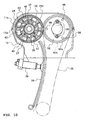
- FIGs. 8 through 10 show the third embodiment.
- the third embodiment is different from the first embodiment in the point that a timing chain 35 is wound around an exhaust-side camshaft 91.
- the exhaust-side camshaft 91 is rotatably supported on a cylinder head 12 by means of cam caps 13.
- Cams 91 a formed on the exhaust-side camshaft 91 allow their respective exhaust valves 93 to be open against urging force of each spring 94.
- the camshaft 91 has a flange 91b formed in its middle section between a pair of cylinders A, B.
- a sprocket member 92 is secured to the flange 91 b with plural bolts 95.
- the sprocket member 92 has a sprocket 92a around which the timing chain 35 is wound, and a gear 92b formed adjacent to the sprocket 92a.
- a scissors gear 96 is secured to a side surface of the sprocket member 92 with a stepped bolt 98.
- the external rotor 28 has a gear 28d on its outer periphery in place of the sprocket 28a, and a ring-shaped member 97 is disposed in place of the intake-side gear member 31 of the first embodiment.
- the ring-shaped member 97 is formed with a width smaller than the intake-side gear member 31 together with a timing-advance path 97a.
- the gear 28d of the intake-side external rotor 28 and the gear 92b of the exhaust-side sprocket member 92 are engaged with each other.
- crankshaft allows the exhaust-side camshaft 91 to rotate via a timing chain 35.
- this also allows the intake-side camshaft 11 to rotate via the sprocket member 92, the external rotor 28 and the like, since the gear 92 of the sprocket member 92 on the exhaust-side camshaft 91 and the gear 28d of the external rotor 28 on the intake-side camshaft 11 are engaged with each other.
- valve timing controller for engine having a camshaft provided with a cam for opening/closing engine valves, and a valve timing controller provided around the camshaft for changing rotational speeds of a crankshaft and the camshaft, wherein the valve timing controller has a perfect circular through hole provided in its center, with a diameter slightly larger than a value equivalent to the sum of a radius of a base circle of the cam and a height of a cam nose; wherein the camshaft has a boss fitted into the through hole of the valve timing controller and a flange adjacent to the boss and radially protruding; and wherein the valve timing controller is mounted to the flange with the through hole fitted through the boss.
- the valve timing controller has an internal rotor provided on the camshaft and an external rotor provided rotatably around the internal rotor, the external rotor is provided with a driven section to which driving force from the crankshaft is inputted, and the internal rotor is formed with the through hole while being mounted to the flange.
- driven section to which the driving force from the crankshaft is inputted include not only a section of the structure which receives the driving force directly from the crankshaft via a chain or the like, but also those of the structure which receive it through an idler shaft or another camshaft.
- the valve timing controller has a given through hole provided in its center to be fixed to the flange with the through hole fitted through the boss of the camshaft, allowing the valve timing controller to be fixed around the outer periphery of the camshaft.
- the valve timing controller has the through hole with its diameter slightly larger than a value equivalent to the sum of a radius of the base circle of the cam, and a height of the cam nose. This allows the cam to pass through the through hole when the valve timing controller is fixed to the camshaft.
- the valve timing controller could be mounted to the camshaft.
- minimizing the diameter of the through hole keeps the outside diameter of the valve timing controller to a minimum while easily ensuring its functions. This also allows securing a sufficient area to which hydraulic pressure is applied without increasing the outside diameter of the valve timing controller operated by hydraulic pressure provided for the hydraulic chamber, for example.
- the internal rotor has a female thread
- the flange has a through hole with male thread, in order for the internal rotor to be fixed from the flange side with a mounting bolt.
- the internal rotor has a female thread, and the flange has a through hole with male thread, in order for the internal rotor to be fixed from the flange side with a mounting bolt, it is unnecessary to form a recess for receiving the head of the mounting bolt, accordingly, reducing the size of the hole formed on the internal rotor, and therefore easily decreasing the diameter of the internal rotor, compared to the case of fixing from the internal rotor side.
- valve timing controller is provided on at least one of the camshafts in pairs, and the external rotor of the valve timing controller is provided with a camshaft driving section for driving the other camshaft.
- camshaft driving section has an outside diameter smaller than that of the driven section.
- valve timing controller is provided on at least one of the camshafts in pairs, and the external rotor of the valve timing controller is provided with a camshaft driving section for driving the other camshaft, this allows the camshaft driving section to have an outside diameter smaller than that of the driven section, accordingly, reducing the size of a camshaft follower attached to the other camshaft as with the camshaft driving section, and therefore decreasing the distance between the paired camshafts. This results in a reduced distance and angle between the plural valves, thereby obtaining a good combustion chamber shape.
- the external rotor is arranged so as to slide on the internal rotor provided around the outer periphery of the boss, and the camshaft driving section, formed as a separate body from the external rotor, is slidably mounted to the flange; and wherein a clearance between the camshaft driving section and the flange is designed smaller than the one between the internal rotor and the external rotor.
- the external rotor might be arranged so as to slide on the internal rotor provided around the outer periphery of the boss, and the camshaft driving section, formed integral with the external rotor as a single unit, might be slidably mounted to the flange, and wherein a clearance between the camshaft driving section and the flange might be designed smaller than the one between the internal rotor and the external rotor.
- the camshaft driving section can thus be attached coaxially to the flange with higher accuracy compared to the driven section, which reduces gear mesh sound produced by the camshaft driving section engaged with a transmitting element such as a gear.
- a position of the mounting bolt is arranged at a position out of phase of the cam nose in the circumferential direction of the camshaft.
- valve timing controller can be easily attached even if the position of the mounting bolt 27 is made closer to the camshaft 11 than the cam nose.
- a mounting structure of a valve timing controller which keeps an outside diameter of the valve timing controller to a minimum, while securing its functions even when it is attached around a camshaft.
- Said mounting structure of a valve timing controller comprises a camshaft 11 provided with a cam 11a for opening/closing engine valves, and a valve timing controller provided around the camshaft 11 for changing rotational speeds of a crankshaft and the camshaft 11, wherein the valve timing controller has a substantially perfect circular through hole provided in its center, with a diameter slightly larger than a value equivalent to the sum of a radius of a base circle 11n of the cam 11a, and a height of a cam nose 11 p; wherein the camshaft 11 has a boss 11 b fitted into the through hole 26f of the valve timing controller and a flange 11c adjacent to the boss 11b and radially protruding; and wherein the valve timing controller is mounted to the flange 11c with the through hole
Landscapes
- Engineering & Computer Science (AREA)
- Mechanical Engineering (AREA)
- General Engineering & Computer Science (AREA)
- Valve Device For Special Equipments (AREA)
- Valve-Gear Or Valve Arrangements (AREA)
Claims (9)
- Motor mit einer Ventilzeitpunktsteuerung (26, 28), wobei eine Nockenwelle (11) mit der Montageanordnung für die Ventilzeitpunktsteuerung (26, 28) versehen ist, aufweisend eine Nabe (11b) und einen Flansch (11c), benachbart zu der Nabe (11b) und radial vorspringend, wobei die Ventilzeitpunktsteuerung (26, 28) an dem Flansch (11c) mit der in eine Durchgangsbohrung (26f) eingesetzten Nabe (11b) montiert ist, dadurch gekennzeichnet, dass die Durchgangsbohrung (26f) der Ventilzeitpunktsteuerung (26, 28) in einer Mitte derselben vorgesehen ist und eine kreisförmige Form hat, mit einem Durchmesser leicht größer als ein Wert, der äquivalent zu einer Summe eines Radius (L1) des Grundkreises (11 n) eines Nockens (11a) und einer Höhe (L2) einer Nockennase (11p) der Nockenwelle (11) ist.
- Motor nach Anspruch 1, dadurch gekennzeichnet, dass die Ventilzeitpunktsteuerung (26, 28) rund um die Nockenwelle für die Phasenveränderung der Beziehung zwischen einer Kurbelwelle und einer Nockenwelle (11) vorgesehen ist.
- Motor nach Anspruch 1 oder 2, dadurch gekennzeichnet, dass die Ventilzeitpunktsteuerung (26, 28) einen inneren Rotor (26) hat, vorgesehen auf der Nockenwelle (11), und einen äußeren Roter (28) hat, vorgesehen drehbar rund um den inneren Rotor (26), dass der äußere Rotor (28) mit einem angetriebenen Abschnitt (28a) versehen ist, auf den die Antriebskraft von der Kurbelwelle eingegeben wird, und dass der innere Rotor (26) mit der Durchgangsbohrung (26f) gebildet ist, während er an dem Flansch (11 c) montiert ist.
- Motor nach zumindest einem der Ansprüche 1 bis 3, dadurch gekennzeichnet, dass der innere Rotor (26) ein Innengewinde (26a) hat und der Flansch (11c) eine Durchgangsbohrung (11 m) mit einem Außengewinde hat, damit der innere Rotor (26) von der Seite des Flansches (11 c) her mit einer Montageschraube (27) befestigt wird.
- Motor nach zumindest einem der Ansprüche 1 bis 4, dadurch gekennzeichnet, dass die Ventilzeitpunktsteuerung (26, 28) auf zumindest einer der Nockenwellen (11) paarweise vorgesehen ist und ein äußerer Rotor (28) der Ventilzeitpunktsteuerung (26, 28) mit einem Nockenwellen- Antriebsabschnitt (31) zum Antrieben der anderen Nockenwelle versehen ist.
- Motor nach Anspruch 6, dadurch gekennzeichnet, dass der Nockenwellen- Antriebsabschnitt (31) einen Außendurchmesser kleiner als derjenige des angetriebenen Abschnittes (28a) hat.
- Motor nach Anspruch 5 oder 6, dadurch gekennzeichnet, dass der äußere Rotor (28) angeordnet ist, um auf dem inneren Rotor (26), vorgesehen rund um den Außenumfang der Nabe (11 b), zu gleiten und der Nockenwellen- Antriebsabschnitt (31), gebildet als ein von dem äußeren Rotor (28) separater Körper auf dem Flansch (11 c) gleitbar montiert ist, wobei ein Spalt zwischen dem Nockenwellen- Antriebsabschnitt (31) und dem Flansch (11 c) kleiner als der zwischen dem inneren Rotor (26) und dem äußeren Rotor (28) festgelegt ist.
- Motor nach Anspruch 5 oder 6, dadurch gekennzeichnet, dass der äußere Rotor (28) angeordnet ist, um auf dem inneren Rotor (26), vorgesehen rund um den Außenumfang der Nabe (11 b), zu gleiten und der Nockenwellen- Antriebsabschnitt (31), einstückig gebildet mit dem äußeren Rotor (28) als eine einzelne Einheit, gleitbar an dem Flansch (11 c) montiert ist, wobei ein Spalt zwischen dem Nockenwellen- Antriebsabschnitt (31) und dem Flansch (11 c) kleiner als der zwischen dem inneren Rotor (26) und dem äußeren Rotor (28) festgelegt ist.
- Motor nach zumindest einem der Ansprüche 1 bis 8, dadurch gekennzeichnet, dass auf der Seite des Flanschs (11 c) der Nockenwelle (11), von der die Schraube (27) montiert ist, eine Position der Montageschraube (27) an einer Position außerhalb der Phase der Nockennase (11 p) in der Umfangsrichtung der Nockenwelle (11) angeordnet ist.
Applications Claiming Priority (2)
| Application Number | Priority Date | Filing Date | Title |
|---|---|---|---|
| JP2003205823A JP4165750B2 (ja) | 2003-08-04 | 2003-08-04 | エンジンのバルブタイミング制御装置の取付構造 |
| JP2003205823 | 2003-08-04 |
Publications (2)
| Publication Number | Publication Date |
|---|---|
| EP1505268A1 EP1505268A1 (de) | 2005-02-09 |
| EP1505268B1 true EP1505268B1 (de) | 2007-12-05 |
Family
ID=33549894
Family Applications (1)
| Application Number | Title | Priority Date | Filing Date |
|---|---|---|---|
| EP04018490A Expired - Lifetime EP1505268B1 (de) | 2003-08-04 | 2004-08-04 | Brennkraftmaschine mit Ventilverstelleinrichtung zentral auf der Nockenwelle montiert |
Country Status (4)
| Country | Link |
|---|---|
| EP (1) | EP1505268B1 (de) |
| JP (1) | JP4165750B2 (de) |
| AT (1) | ATE380287T1 (de) |
| DE (1) | DE602004010467T2 (de) |
Families Citing this family (2)
| Publication number | Priority date | Publication date | Assignee | Title |
|---|---|---|---|---|
| JP2007127057A (ja) * | 2005-11-04 | 2007-05-24 | Mikuni Corp | バルブタイミング調整装置の取付構造 |
| JP2013524092A (ja) * | 2010-04-06 | 2013-06-17 | ボーグワーナー インコーポレーテッド | 同心カムシャフトに沿って中央に配置したカム位相器 |
Family Cites Families (9)
| Publication number | Priority date | Publication date | Assignee | Title |
|---|---|---|---|---|
| JPS61197705A (ja) * | 1985-02-27 | 1986-09-02 | Yamaha Motor Co Ltd | 内燃機関のカムチエン外れ防止機構 |
| JPH0219521Y2 (de) * | 1985-04-17 | 1990-05-30 | ||
| EP1074722A1 (de) * | 1998-04-22 | 2001-02-07 | Toyota Jidosha Kabushiki Kaisha | Einlassluftvolumendetektierungsvorrichtung für eine brennkraftmaschine |
| DE19983890T1 (de) * | 1999-11-10 | 2002-03-07 | Mitsubishi Electric Corp | Ventiltaktgebungsjustiereinrichtung |
| US6247434B1 (en) * | 1999-12-28 | 2001-06-19 | Borgwarner Inc. | Multi-position variable camshaft timing system actuated by engine oil |
| JP4224944B2 (ja) * | 2000-03-01 | 2009-02-18 | トヨタ自動車株式会社 | 内燃機関のバルブタイミング制御装置 |
| DE10102767A1 (de) * | 2001-01-23 | 2002-07-25 | Volkswagen Ag | Steuertrieb für Ventile einer Brennkraftmaschine |
| DE10116707B4 (de) * | 2001-04-04 | 2017-01-19 | Schaeffler Technologies AG & Co. KG | Vorrichtung zur Relativverdrehung einer Nockenwelle gegenüber einer Kurbelwelle einer Brennkraftmaschine |
| JP2003113703A (ja) * | 2001-10-03 | 2003-04-18 | Denso Corp | バルブタイミング調整装置 |
-
2003
- 2003-08-04 JP JP2003205823A patent/JP4165750B2/ja not_active Expired - Lifetime
-
2004
- 2004-08-04 DE DE602004010467T patent/DE602004010467T2/de not_active Expired - Lifetime
- 2004-08-04 EP EP04018490A patent/EP1505268B1/de not_active Expired - Lifetime
- 2004-08-04 AT AT04018490T patent/ATE380287T1/de not_active IP Right Cessation
Also Published As
| Publication number | Publication date |
|---|---|
| ATE380287T1 (de) | 2007-12-15 |
| DE602004010467D1 (de) | 2008-01-17 |
| JP4165750B2 (ja) | 2008-10-15 |
| DE602004010467T2 (de) | 2008-04-30 |
| JP2005054591A (ja) | 2005-03-03 |
| EP1505268A1 (de) | 2005-02-09 |
Similar Documents
| Publication | Publication Date | Title |
|---|---|---|
| US6006708A (en) | Valve timing controlling apparatus for internal combustion engine | |
| EP0915234B1 (de) | Vorrichtung zur Änderung der Ventilzeitsteuerung einer Brennkraftmaschine | |
| JP3847428B2 (ja) | 内燃エンジンのシリンダヘッド構造 | |
| US5724929A (en) | Engine variable valve timing mechanism | |
| US6244230B1 (en) | Variable valve timing apparatus | |
| US9133734B2 (en) | Valve timing control apparatus for internal combustion engine | |
| EP1447529B1 (de) | Phasenversteller mit einem einzigen Rückführungsrückschlagventil und einem Zufuhrventil | |
| EP1400661A1 (de) | Schieberventilsvorrichung zur Betätigung des Verriegelungsstifts eines Nockenwellenverstellers | |
| JP3561467B2 (ja) | エンジンの動弁制御装置 | |
| JP2010196698A (ja) | 弁開閉時期制御装置 | |
| EP1359291B1 (de) | Hydraulische Dämpfung eines Mechanismuses für variable Ventilsteuerung | |
| EP1357260B1 (de) | Verriegelungsstift eines Nockenwellenverstellers mit gekrümmter Entlüftungsstrecke zur Erzeugung einer hydraulischen Verzögerung | |
| US6575127B2 (en) | Valve operating control system in engine | |
| JP4165382B2 (ja) | バルブタイミング調整装置 | |
| US9816408B2 (en) | Camshaft phaser | |
| EP1505268B1 (de) | Brennkraftmaschine mit Ventilverstelleinrichtung zentral auf der Nockenwelle montiert | |
| US6883479B2 (en) | VCT phaser having an electromagnetic lock system for shift and lock operation | |
| EP1505267B1 (de) | Ventilverstelleinrichtung einer Brennkraftmaschine | |
| US8800516B2 (en) | Variable valve timing control apparatus | |
| JPH09250310A (ja) | 内燃機関のバルブタイミング変更装置 | |
| JPH10159519A (ja) | 内燃機関のバルブタイミング制御装置 | |
| JPH11280414A (ja) | 可変バルブタイミング装置付dohcエンジン | |
| JP4045766B2 (ja) | エンジンの動弁装置 | |
| JP4223342B2 (ja) | バルブタイミング制御装置を有するエンジン | |
| JP4026461B2 (ja) | 弁開閉時期制御装置 |
Legal Events
| Date | Code | Title | Description |
|---|---|---|---|
| PUAI | Public reference made under article 153(3) epc to a published international application that has entered the european phase |
Free format text: ORIGINAL CODE: 0009012 |
|
| AK | Designated contracting states |
Kind code of ref document: A1 Designated state(s): AT BE BG CH CY CZ DE DK EE ES FI FR GB GR HU IE IT LI LU MC NL PL PT RO SE SI SK TR |
|
| AX | Request for extension of the european patent |
Extension state: AL HR LT LV MK |
|
| 17P | Request for examination filed |
Effective date: 20041217 |
|
| 17Q | First examination report despatched |
Effective date: 20050405 |
|
| AKX | Designation fees paid |
Designated state(s): AT BE BG CH CY CZ DE DK EE ES FI FR GB GR HU IE IT LI LU MC NL PL PT RO SE SI SK TR |
|
| GRAP | Despatch of communication of intention to grant a patent |
Free format text: ORIGINAL CODE: EPIDOSNIGR1 |
|
| GRAS | Grant fee paid |
Free format text: ORIGINAL CODE: EPIDOSNIGR3 |
|
| GRAA | (expected) grant |
Free format text: ORIGINAL CODE: 0009210 |
|
| AK | Designated contracting states |
Kind code of ref document: B1 Designated state(s): AT BE BG CH CY CZ DE DK EE ES FI FR GB GR HU IE IT LI LU MC NL PL PT RO SE SI SK TR |
|
| REG | Reference to a national code |
Ref country code: GB Ref legal event code: FG4D |
|
| REG | Reference to a national code |
Ref country code: IE Ref legal event code: FG4D |
|
| REG | Reference to a national code |
Ref country code: CH Ref legal event code: EP |
|
| REF | Corresponds to: |
Ref document number: 602004010467 Country of ref document: DE Date of ref document: 20080117 Kind code of ref document: P |
|
| PG25 | Lapsed in a contracting state [announced via postgrant information from national office to epo] |
Ref country code: LI Free format text: LAPSE BECAUSE OF FAILURE TO SUBMIT A TRANSLATION OF THE DESCRIPTION OR TO PAY THE FEE WITHIN THE PRESCRIBED TIME-LIMIT Effective date: 20071205 Ref country code: ES Free format text: LAPSE BECAUSE OF FAILURE TO SUBMIT A TRANSLATION OF THE DESCRIPTION OR TO PAY THE FEE WITHIN THE PRESCRIBED TIME-LIMIT Effective date: 20080316 Ref country code: SE Free format text: LAPSE BECAUSE OF FAILURE TO SUBMIT A TRANSLATION OF THE DESCRIPTION OR TO PAY THE FEE WITHIN THE PRESCRIBED TIME-LIMIT Effective date: 20080305 Ref country code: NL Free format text: LAPSE BECAUSE OF FAILURE TO SUBMIT A TRANSLATION OF THE DESCRIPTION OR TO PAY THE FEE WITHIN THE PRESCRIBED TIME-LIMIT Effective date: 20071205 Ref country code: CH Free format text: LAPSE BECAUSE OF FAILURE TO SUBMIT A TRANSLATION OF THE DESCRIPTION OR TO PAY THE FEE WITHIN THE PRESCRIBED TIME-LIMIT Effective date: 20071205 |
|
| PG25 | Lapsed in a contracting state [announced via postgrant information from national office to epo] |
Ref country code: SI Free format text: LAPSE BECAUSE OF FAILURE TO SUBMIT A TRANSLATION OF THE DESCRIPTION OR TO PAY THE FEE WITHIN THE PRESCRIBED TIME-LIMIT Effective date: 20071205 Ref country code: PL Free format text: LAPSE BECAUSE OF FAILURE TO SUBMIT A TRANSLATION OF THE DESCRIPTION OR TO PAY THE FEE WITHIN THE PRESCRIBED TIME-LIMIT Effective date: 20071205 Ref country code: FI Free format text: LAPSE BECAUSE OF FAILURE TO SUBMIT A TRANSLATION OF THE DESCRIPTION OR TO PAY THE FEE WITHIN THE PRESCRIBED TIME-LIMIT Effective date: 20071205 |
|
| NLV1 | Nl: lapsed or annulled due to failure to fulfill the requirements of art. 29p and 29m of the patents act | ||
| REG | Reference to a national code |
Ref country code: CH Ref legal event code: PL |
|
| PG25 | Lapsed in a contracting state [announced via postgrant information from national office to epo] |
Ref country code: AT Free format text: LAPSE BECAUSE OF FAILURE TO SUBMIT A TRANSLATION OF THE DESCRIPTION OR TO PAY THE FEE WITHIN THE PRESCRIBED TIME-LIMIT Effective date: 20071205 |
|
| PG25 | Lapsed in a contracting state [announced via postgrant information from national office to epo] |
Ref country code: CZ Free format text: LAPSE BECAUSE OF FAILURE TO SUBMIT A TRANSLATION OF THE DESCRIPTION OR TO PAY THE FEE WITHIN THE PRESCRIBED TIME-LIMIT Effective date: 20071205 |
|
| PG25 | Lapsed in a contracting state [announced via postgrant information from national office to epo] |
Ref country code: BE Free format text: LAPSE BECAUSE OF FAILURE TO SUBMIT A TRANSLATION OF THE DESCRIPTION OR TO PAY THE FEE WITHIN THE PRESCRIBED TIME-LIMIT Effective date: 20071205 Ref country code: RO Free format text: LAPSE BECAUSE OF FAILURE TO SUBMIT A TRANSLATION OF THE DESCRIPTION OR TO PAY THE FEE WITHIN THE PRESCRIBED TIME-LIMIT Effective date: 20071205 Ref country code: SK Free format text: LAPSE BECAUSE OF FAILURE TO SUBMIT A TRANSLATION OF THE DESCRIPTION OR TO PAY THE FEE WITHIN THE PRESCRIBED TIME-LIMIT Effective date: 20071205 |
|
| PG25 | Lapsed in a contracting state [announced via postgrant information from national office to epo] |
Ref country code: PT Free format text: LAPSE BECAUSE OF FAILURE TO SUBMIT A TRANSLATION OF THE DESCRIPTION OR TO PAY THE FEE WITHIN THE PRESCRIBED TIME-LIMIT Effective date: 20080505 |
|
| EN | Fr: translation not filed | ||
| PLBE | No opposition filed within time limit |
Free format text: ORIGINAL CODE: 0009261 |
|
| STAA | Information on the status of an ep patent application or granted ep patent |
Free format text: STATUS: NO OPPOSITION FILED WITHIN TIME LIMIT |
|
| PG25 | Lapsed in a contracting state [announced via postgrant information from national office to epo] |
Ref country code: DK Free format text: LAPSE BECAUSE OF FAILURE TO SUBMIT A TRANSLATION OF THE DESCRIPTION OR TO PAY THE FEE WITHIN THE PRESCRIBED TIME-LIMIT Effective date: 20071205 |
|
| 26N | No opposition filed |
Effective date: 20080908 |
|
| PG25 | Lapsed in a contracting state [announced via postgrant information from national office to epo] |
Ref country code: GR Free format text: LAPSE BECAUSE OF FAILURE TO SUBMIT A TRANSLATION OF THE DESCRIPTION OR TO PAY THE FEE WITHIN THE PRESCRIBED TIME-LIMIT Effective date: 20080306 |
|
| PG25 | Lapsed in a contracting state [announced via postgrant information from national office to epo] |
Ref country code: MC Free format text: LAPSE BECAUSE OF NON-PAYMENT OF DUE FEES Effective date: 20080831 |
|
| PG25 | Lapsed in a contracting state [announced via postgrant information from national office to epo] |
Ref country code: BG Free format text: LAPSE BECAUSE OF FAILURE TO SUBMIT A TRANSLATION OF THE DESCRIPTION OR TO PAY THE FEE WITHIN THE PRESCRIBED TIME-LIMIT Effective date: 20080305 Ref country code: EE Free format text: LAPSE BECAUSE OF FAILURE TO SUBMIT A TRANSLATION OF THE DESCRIPTION OR TO PAY THE FEE WITHIN THE PRESCRIBED TIME-LIMIT Effective date: 20071205 Ref country code: FR Free format text: LAPSE BECAUSE OF FAILURE TO SUBMIT A TRANSLATION OF THE DESCRIPTION OR TO PAY THE FEE WITHIN THE PRESCRIBED TIME-LIMIT Effective date: 20081003 |
|
| PG25 | Lapsed in a contracting state [announced via postgrant information from national office to epo] |
Ref country code: IE Free format text: LAPSE BECAUSE OF NON-PAYMENT OF DUE FEES Effective date: 20080804 Ref country code: CY Free format text: LAPSE BECAUSE OF FAILURE TO SUBMIT A TRANSLATION OF THE DESCRIPTION OR TO PAY THE FEE WITHIN THE PRESCRIBED TIME-LIMIT Effective date: 20071205 |
|
| PG25 | Lapsed in a contracting state [announced via postgrant information from national office to epo] |
Ref country code: HU Free format text: LAPSE BECAUSE OF FAILURE TO SUBMIT A TRANSLATION OF THE DESCRIPTION OR TO PAY THE FEE WITHIN THE PRESCRIBED TIME-LIMIT Effective date: 20080606 Ref country code: LU Free format text: LAPSE BECAUSE OF NON-PAYMENT OF DUE FEES Effective date: 20080804 |
|
| PG25 | Lapsed in a contracting state [announced via postgrant information from national office to epo] |
Ref country code: TR Free format text: LAPSE BECAUSE OF FAILURE TO SUBMIT A TRANSLATION OF THE DESCRIPTION OR TO PAY THE FEE WITHIN THE PRESCRIBED TIME-LIMIT Effective date: 20071205 |
|
| P01 | Opt-out of the competence of the unified patent court (upc) registered |
Effective date: 20230527 |
|
| PGFP | Annual fee paid to national office [announced via postgrant information from national office to epo] |
Ref country code: IT Payment date: 20230825 Year of fee payment: 20 Ref country code: GB Payment date: 20230824 Year of fee payment: 20 |
|
| PGFP | Annual fee paid to national office [announced via postgrant information from national office to epo] |
Ref country code: DE Payment date: 20230821 Year of fee payment: 20 |
|
| REG | Reference to a national code |
Ref country code: DE Ref legal event code: R071 Ref document number: 602004010467 Country of ref document: DE |
|
| REG | Reference to a national code |
Ref country code: GB Ref legal event code: PE20 Expiry date: 20240803 |
|
| PG25 | Lapsed in a contracting state [announced via postgrant information from national office to epo] |
Ref country code: GB Free format text: LAPSE BECAUSE OF EXPIRATION OF PROTECTION Effective date: 20240803 |
|
| PG25 | Lapsed in a contracting state [announced via postgrant information from national office to epo] |
Ref country code: GB Free format text: LAPSE BECAUSE OF EXPIRATION OF PROTECTION Effective date: 20240803 |