EP1505560B1 - Lichtleiterbauteil für optische Mehrsegmentsanzeigen - Google Patents
Lichtleiterbauteil für optische Mehrsegmentsanzeigen Download PDFInfo
- Publication number
- EP1505560B1 EP1505560B1 EP04015509A EP04015509A EP1505560B1 EP 1505560 B1 EP1505560 B1 EP 1505560B1 EP 04015509 A EP04015509 A EP 04015509A EP 04015509 A EP04015509 A EP 04015509A EP 1505560 B1 EP1505560 B1 EP 1505560B1
- Authority
- EP
- European Patent Office
- Prior art keywords
- optical waveguide
- waveguide component
- component according
- light
- optical
- Prior art date
- Legal status (The legal status is an assumption and is not a legal conclusion. Google has not performed a legal analysis and makes no representation as to the accuracy of the status listed.)
- Expired - Lifetime
Links
Images
Classifications
-
- G—PHYSICS
- G09—EDUCATION; CRYPTOGRAPHY; DISPLAY; ADVERTISING; SEALS
- G09F—DISPLAYING; ADVERTISING; SIGNS; LABELS OR NAME-PLATES; SEALS
- G09F9/00—Indicating arrangements for variable information in which the information is built-up on a support by selection or combination of individual elements
- G09F9/30—Indicating arrangements for variable information in which the information is built-up on a support by selection or combination of individual elements in which the desired character or characters are formed by combining individual elements
- G09F9/302—Indicating arrangements for variable information in which the information is built-up on a support by selection or combination of individual elements in which the desired character or characters are formed by combining individual elements characterised by the form or geometrical disposition of the individual elements
- G09F9/3023—Segmented electronic displays
-
- G—PHYSICS
- G09—EDUCATION; CRYPTOGRAPHY; DISPLAY; ADVERTISING; SEALS
- G09F—DISPLAYING; ADVERTISING; SIGNS; LABELS OR NAME-PLATES; SEALS
- G09F9/00—Indicating arrangements for variable information in which the information is built-up on a support by selection or combination of individual elements
- G09F9/30—Indicating arrangements for variable information in which the information is built-up on a support by selection or combination of individual elements in which the desired character or characters are formed by combining individual elements
- G09F9/302—Indicating arrangements for variable information in which the information is built-up on a support by selection or combination of individual elements in which the desired character or characters are formed by combining individual elements characterised by the form or geometrical disposition of the individual elements
-
- G—PHYSICS
- G09—EDUCATION; CRYPTOGRAPHY; DISPLAY; ADVERTISING; SEALS
- G09F—DISPLAYING; ADVERTISING; SIGNS; LABELS OR NAME-PLATES; SEALS
- G09F9/00—Indicating arrangements for variable information in which the information is built-up on a support by selection or combination of individual elements
- G09F9/30—Indicating arrangements for variable information in which the information is built-up on a support by selection or combination of individual elements in which the desired character or characters are formed by combining individual elements
- G09F9/33—Indicating arrangements for variable information in which the information is built-up on a support by selection or combination of individual elements in which the desired character or characters are formed by combining individual elements being semiconductor devices, e.g. diodes
Definitions
- the present invention relates to a light guide member having a light entrance side and a light exit side for multi-segment optical displays, comprising a mask in which for each segment a light guide is guided in the form of the segment, and which is manufactured in 2K injection molding technology, and a corresponding optical assembly, which is set up for a multi-segment display, a household appliance with such an optical assembly and a method for manufacturing the optical fiber component in 2K injection molding.
- 7-segment displays with LED display for number displays in household appliances. These LED displays are available with different digit heights, display colors and number of digits with and without decimal point.
- the LED displays have on their underside connection pins, which are inserted for electrical connection of the LED display in connection holes of a printed circuit board and soldered there.
- the 7-segment displays are generally positioned behind a window in a panel of the household appliance.
- a disadvantage is that the fixed height of the LED displays determines the installation depth of the circuit board behind the panel. Due to requirements of the diaphragm design or the mechanical structure of the diaphragm, it may be necessary to change the installation depth of the circuit board behind the panel. Increasing the overall height of the LED displays is only possible to a limited extent by extending the connection pins or an additional display base, so that the display quality deteriorates with larger installation depths. A reduction in the height is usually not possible.
- Out DE 101 12 640 C1 is a display device for household appliances with display segments known in which juxtaposed light guide in the form of light fingers through guide channels in guide bodies through.
- the display device is composed along the Lichtleitweges of several guide bodies, wherein the juxtaposed light fingers are manufacturing reasons connected to each other by a photoconductive plate.
- This has the disadvantage that light is coupled into adjacent segments via this connection, as a result of which light disturbances occur in the individual segments, which deteriorate the display quality. Therefore, it is necessary to cover the display area with a contour shutter to cover the light disturbances and thus achieve sharper contours.
- a light guide component for optical multi-segment displays is known, which is made of two plastic components (2K) in 2K injection molding.
- a mask is first made from a first plastic component, into which then a second plastic component is injected as a light guide.
- the choice of materials is subject to the condition that the mask must not deform significantly during the injection of the optical waveguide material in order not to impair the light-guiding property of the optical waveguide.
- the known optical fiber component has a mask made of high glass fiber-filled polyamide and a light guide of polymethyl methacrylate.
- the optical fiber with the mask at least partially connects adhesively, whereby the light transmission property of the optical fiber and thus the display quality is reduced.
- the fine patterning and the length of the optical fiber device are severely limited. Accordingly, and also due to the relatively high light losses in the optical fiber component only a short Lichtleitin is possible and thus limits the installation depth of the circuit board behind the aperture.
- the invention has for its object to provide a cost-effective optical fiber component for optical multi-segment displays available, with which the installation depth of the circuit board behind a display surface with high display quality can be made variable.
- This object is achieved in a light guide component of the type mentioned in that between the mask and the light guide is continuously formed an air gap, in particular in the micrometer range. Through this air gap, light propagating in the light guide is totally reflected at the interface with the air gap, whereby the light is guided further in the light guide and is not absorbed by the mask material. In this way, it is possible to keep the light losses low for optical fibers of great length, so that a high luminance and thus a high display quality is achieved on the display surface.
- the mask material is a light-tight, easily flowing material with a low volume shrinkage during the cooling process.
- the mask material is a liquid crystalline polymer (LCP), such as Vectra®. Due to the processing properties of this mask material a production of long and filigree masks is possible.
- LCP liquid crystalline polymer
- This has the advantage that optical fiber components can be manufactured with a large length, so that at large installation depths of the circuit board behind a display surface, the light can be guided by means of the optical fiber component to the display surface, whereby a high display quality is achieved.
- a small width of the individual segments can be realized in this mask material and, in addition to an improved visual appearance of the multisegment display, also a high display quality can be achieved.
- the optical waveguide material is a transparent amorphous plastic, in particular polymethylmethacrylate (PMMA).
- PMMA polymethylmethacrylate
- This light guide material has the advantage that it does not form a bond with the mask material LCP and shrinks strongly on cooling.
- a continuous air gap can form between the optical fiber and the mask. That The air gap is formed by a higher volume shrinkage of the optical waveguide material compared to the mask material during the cooling process and is therefore largely independent of the manufacturing process, which leads to a high process reliability.
- PMMA has the advantage that it has a much lower melting point than the mask material LCP.
- the manufacturing parameters may be adjusted to the melting temperature of the mask material such that fusing of the mask material upon injection of the optical fiber material into the forming mask is minimized.
- This has the advantage that the light guide is formed exactly in the light guide geometry predetermined by the mask, since the light guide material does not melt the mask material during the production process and thus deforms, whereby a high quality of the light guide and thus a high display quality can be achieved.
- the optical waveguide material is injected into the mask via a mass cushion on the light exit side.
- this has indirect injection of the optical fiber material in the segment of the mask has the advantage that the light guide streaks and bubbles produced and thus a high quality of the light guide can be achieved.
- the light-conducting material on the light exit side of the light-conducting component forms a light-conducting plate to which, in particular, the light guide of each segment is connected. This has the advantage that the light guide of each segment is fixed by the plate.
- the photoconductive plate can be made such that it has a rough and / or a structured surface.
- the rough surface scatters the emerging light, making the light distribution of each segment uniform.
- the structured surface highlights the structure of the individual segments, which makes the display easy to see from oblique angles.
- At least one injection point of the optical waveguide material is arranged between the segments.
- the light-guiding material can be injected uniformly into the individual segments.
- Another advantage is that the injection point does not interfere with the light emission from the individual segments, whereby a homogeneous light distribution for each segment can be achieved.
- the photoconductive plate protrudes laterally beyond the mask.
- the shape of the plate is adapted to a panel.
- latching elements for fastening the optical waveguide component to a housing part and / or to a diaphragm part are formed on the plate, so that an optical assembly, which is set up with the optical waveguide component for a multi-segment display, by means of these locking elements of the optical waveguide component on the housing or on the diaphragm, for example a household appliance can be locked. In this way, a mounting of the optical fiber component and thus the optical assembly in a particularly simple manner possible.
- the optical fiber is polished at the light entrance side. In this way, a scattering of the incoming light can be reduced, whereby more light enters the light guide. This has the advantage that even with long light guides a display with high luminance can be achieved.
- the optical waveguide component has on the light entry side for each segment a recess for enclosing a light-emitting component, in particular for enclosing an SMD LED.
- a recess for enclosing a light-emitting component in particular for enclosing an SMD LED.
- a particularly good coupling of the light from the SMD LED into the light guide can be achieved by filling the recess of the light guide component, which contains the SMD LED, with a transparent potting compound and / or with diffuser material. In this way, the number of optical transitions is reduced, thus minimizing the loss of light.
- the light of the light source can be coupled particularly evenly distributed in the light guide of the respective segment due to the scattering in the diffuser material.
- the mask is cuboid and has latching elements for fastening the optical fiber component to a printed circuit board and / or on a housing part, in particular on the light entry side.
- the optical fiber device can be easily mounted on the circuit board.
- the optical waveguide component can be latched on the light entry side with an electronic circuit board on which the SMD LEDs are arranged.
- one of the light entrance side associated square surface per locking element is arranged so that it is directed freely movable from one to the associated, parallel to the optical waveguide square edge on the circuit board, and the two remaining, to the light guides parallel edges each have a line-shaped, formed in a negative mold to the locking element recess which is positively connected with the latching element of an adjacent light guide component.
- the optical fiber material and / or the mask material is colored in itself.
- the optical waveguide and / or the mask is colored in accordance with the housing or the diaphragm. This has the advantage that the optical waveguide component and thus the optical subassembly with the optical waveguide component can be optically adapted to the housing or the diaphragm such that only the display is visible on the display surface.
- optical fiber component is preferably used in optical assemblies that are set up for multi-segment displays, in particular for 7-segment displays.
- optical assemblies are used as display devices in the housing or the bezel of household appliances, since in this way modifications of the housing or bezel design can be performed without the circuit board or the electronics must be changed.
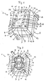
- a light guide component 1 for a 7-segment optical display with a decimal point is shown schematically.
- the optical waveguide component 1 consists of a cuboid main body 2 which forms a mask M with parallel channels K, the mask M corresponding in cross section to a 7-segment display with a decimal point.
- a light guide 3 with a segmental cross-sectional area and for the decimal point a light guide 4 is guided with a circular cross-sectional area from a light entrance side 5 to one of the light entrance side 5 opposite light exit side 6 for each of the seven segments of the 7-segment display ,
- the light guides 3, 4 open into a light-conducting plate 7, which is arranged on the base body 2 and has a planar surface 8.
- the light guides 3, 4 are in FIG. 1 shown by dashed lines, since they are below the photoconductive plate 7.
- Each of the segment-shaped light guides 3 has a width B and the circular light guide 4 has a diameter D, both of which are in particular less than or equal to one millimeter.
- the individual segmental light guides 3 are separated from one another by webs S of the mask M continuously from the light entrance side 5 to the light exit side 6.
- each locking element 11 On the main body 2, which is in particular cuboid, is arranged at two diagonally opposite corners of the Lichteintrittseite 5 associated rectangular surface each locking element 11 so that it starting from one of the associated, parallel to the optical fibers 3, 4 cuboid edge 10th protrudes beyond the light entry side 5 of the optical fiber component 1 and is freely movable.
- the base body 2 At the two remaining, parallel to the light guides 3, 4 edges 12, the base body 2 each have a line-shaped recess 13 which is formed form-fitting manner to the locking elements 11.
- the curvature 14 of the locking elements 11 corresponds in its negative shape of the curvature 15 of the recesses 13.
- another identical optical fiber component 1 can be arranged without gaps (not shown), since the locking element 11 fits into the recess 13 in a form-fitting manner.
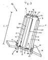
- FIG. 3 is a section along the light guides 3, 4 shown by an optical assembly 16, which is adapted for the optical 7-segment display.
- the optical assembly 16 includes the optical fiber device 1 and a printed circuit board 17 with SMD LEDs 18 as light-emitting components.
- the light guide component 1 is latched with its locking elements 11 in holes 19 of the circuit board 17.
- the SMD LEDs 18 are encompassed by the recesses 9 of the optical waveguide component 1, so that light emitted by the SMD LEDs can propagate along the optical waveguides 3, 4 only in the direction marked by arrows. Overcoupling of light of the SMD LED in adjacent light guides 3, 4 is avoided in that on the light entrance side 5, the light guide component 1 between the recesses 9 positively closes with the circuit board 17.
- These recesses 9 can be filled in particular with the use of SMD LED chips 18 without LED housing with a transparent potting compound, on the one hand protects the SMD LED chips 18 from damage and on the other hand, the light coupling of the emitted light in the light guide. 3 , 4, since the number of optical transitions is reduced and the transparent potting compound can be selected such that its optical refractive index is matched to that of the optical waveguide 3, 4.
- the recesses 9 can also be filled with diffuser material, by which light emitted by the SMD LEDs is scattered, so that the light enters the light guides 3, 4 with a uniform distribution. In general, other light-emitting components can be used, such as LEDs or incandescent lamps, the dimensions of the optical fiber component can be adjusted accordingly.
- an air gap 20 is formed in the channels K throughout the entire length L of the light guide 3, 4 from the light entrance side 5 to the light exit side 6, which is in particular of the order of microns.
- the light emitted by the SMD LED 18 and coupled on the light entrance side 5 in the light guide 3, 4 light that propagates in the light guide 3, 4 and which meets the air gap 20 in the light guide 3, 4 reflected back , In this way, the light is guided in the light guide 3, 4 and not absorbed by the base body 2.
- optical fibers 3, 4 with a long length L to keep the light losses low.
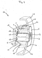
- FIG. 4 schematically shows a section along the light guide 3 through a shutter member 23 with an optical assembly 16 which is adapted according to a further embodiment of the invention for a multi-segment optical display.
- the light-conducting plate 7 extends in its planar extension beyond the base body 2 and has a curved shape, which is adapted to the curvature of the diaphragm part 23.
- the outer contour may, as shown, have a rectangular shape or any other desired shape.
- 7 latching elements 24 are integrally formed on the photoconductive plate 7, which are bounded on the light exit side 6 of the plate 7 and parallel to the light guide component 1 to the light entrance side 5 point.
- counter-locking elements 25 are formed, with which the latching elements 25 are latched for mounting the optical assembly 16 on the panel part 23.
- the optical fiber component 1 is manufactured in 2K injection molding technology from two plastic components (2K).
- the base body 2 with the mask M is made from an opaque, easily flowing material with a low volume shrinkage during the cooling process, which according to the invention is a liquid-crystalline polymer (LCP), such as Vectra®. Due to the processing properties of this liquid-crystalline polymer, the production of long and filigree masks M is possible.
- the light guide 3, 4 are injected from a second translucent plastic, which does not connect to the plastic of the mask M and according to the invention is a transparent amorphous plastic, in particular polymethylmethacrylate (PMMA).
- PMMA polymethylmethacrylate
- the PMMA has a lower melting point than LCP, so that the temperature of the PMMA melt during the manufacturing process can be chosen so that the mask M does not melt when injecting the PMMA as possible.
- the PMMA is injected via a ground pad P at the light exit side 6 in the mask M, which forms the photoconductive plate 7.
- FIG. 1 are centrally shown between the individual light guides 3 two injection points A in dotted lines through which the ground pad P is filled with PMMA. Starting from this mass cushion P, the PMMA is pressed into channels K of the mask M.
- a volume shrinkage occurs. This is very low for an LCP, such as Vectra®, while the volume shrinkage of PMMA is in the order of 0.6%.
- the volume shrinkage of the optical waveguide material compared to the mask material during the cooling process is significantly higher, resulting in a over the entire length L of the optical fibers 3, 4 continuous air gap 20 between optical fibers 3, 4 and mask M is formed.
- the formation of the air gap 20 largely independent of the manufacturing process, resulting in a high process reliability for the production of the optical fiber components 1.
- the optical waveguide component 1 can be manufactured with a ratio of length L to width B or diameter D of the optical waveguides 3, 4 which is greater than 13 or on the order of 30.
- the width B or the diameter D of the light guides 3, 4 may be less than or equal to 1 millimeter and the length L of the light guides 35 millimeters.
- a digit height of the 7-segment display of 10 millimeters can be realized with a segment width of 1 millimeter and an optical fiber length of 35 millimeters.
- other dimensions of the optical waveguide component 1 are also possible.
- the plastic for forming the light guides 3, 4 or the light-guiding plate 7 and / or the plastic for forming the main body 2 may be colored in itself.
- the light guides 3, 4 and the photoconductive plate 7 may be adapted in color to the panel part 23 or to a housing part such that segments of the multi-segment display are visible only when illuminated.
- the light-emitting components can be chosen such that they emit colored light, so that there is a color contrast between illuminated and unlit segments of the multi-segment display.
Landscapes
- Physics & Mathematics (AREA)
- General Physics & Mathematics (AREA)
- Engineering & Computer Science (AREA)
- Theoretical Computer Science (AREA)
- Optical Couplings Of Light Guides (AREA)
- Devices For Indicating Variable Information By Combining Individual Elements (AREA)
- Moulds For Moulding Plastics Or The Like (AREA)
- Injection Moulding Of Plastics Or The Like (AREA)
- Optical Fibers, Optical Fiber Cores, And Optical Fiber Bundles (AREA)
Description
- Die vorliegende Erfindung betrifft ein Lichtleiterbauteil mit einer Lichteintrittseite und einer Lichtaustrittseite für optische Mehrsegmentanzeigen, das eine Maske umfasst, in der für jedes Segment ein Lichtleiter in Form des Segments geführt ist, und das in 2K-Spritzgusstechnik gefertigt ist, sowie eine entsprechende optische Baugruppe, die für eine Mehrsegmentanzeige eingerichtet ist, ein Haushaltgerät mit einer solchen optischen Baugruppe und ein Verfahren zur Fertigung des Lichtleiterbauteils in 2K-Spritzgusstechnik.
- Es ist bekannt, für Zahlenanzeigen bei Haushaltgeräten 7-Segmentanzeigen mit LED-Display zu verwenden. Diese LED-Displays stehen mit unterschiedlichen Ziffernhöhen, Anzeigefarben und Ziffernzahl mit und ohne Dezimalpunkt zur Verfügung. Die LED-Displays weisen an ihrer Unterseite Anschlusspins auf, die zur elektrischen Verbindung des LED-Displays in Anschlussbohrungen einer Leiterplatte eingesteckt und dort verlötet werden. Bei Haushaltgeräten werden die 7-Segmentanzeigen im allgemeinen hinter einem Fenster in einer Blende des Haushaltgerätes positioniert. Nachteilig ist dabei, dass die feste Bauhöhe der LED-Displays die Einbautiefe der Leiterplatte hinter der Blende festlegt. Durch Anforderungen des Blendendesigns oder des mechanischen Aufbaus der Blende kann es notwendig werden, die Einbautiefe der Leiterplatte hinter der Blende zu verändern. Eine Vergrößerung der Bauhöhe der LED-Displays ist durch Verlängerung der Anschlusspins oder durch einen zusätzlichen Displaysockel nur eingeschränkt möglich, so dass sich bei größeren Einbautiefen die Anzeigequalität verschlechtert. Eine Verringerung der Bauhöhe ist in der Regel überhaupt nicht möglich.
- Aus
DE 101 12 640 C1 ist eine Anzeigeeinrichtung für Haushaltgeräte mit AnzeigeSegmenten bekannt, bei der nebeneinander angeordnete Lichtleiter in Form von Lichtfingern durch Führungskanäle in Führungskörpern hindurch verlaufen. Die Anzeigeeinrichtung setzt sich längs des Lichtleitweges aus mehreren Führungskörpern zusammen, wobei die nebeneinander angeordneten Lichtfinger fertigungsbedingt miteinander durch eine lichtleitende Platte verbunden sind. Dies hat den Nachteil, dass über diese Verbindung Licht in benachbarte Segmente eingekoppelt wird, wodurch Lichtstörungen in den einzelnen Segmenten entstehen, die die Anzeigequalität verschlechtern. Deswegen ist es notwendig die Anzeigefläche mit einer Konturblende abzudecken, um die Lichtstörungen abzudecken und somit schärfere Konturen zu erzielen. - Aus der Steuerung einer Waschmaschine der Firma AEG ist ein Lichtleiterbauteil für optische Mehrsegmentanzeigen bekannt, das aus zwei Kunststoffkomponenten (2K) in 2K-Spritzgußtechnik gefertigt ist. Dabei wird zuerst aus einer ersten Kunststoffkomponente eine Maske gefertigt, in die dann eine zweite Kunststoffkomponente als Lichtleiter eingespritzt wird. Die Materialauswahl unterliegt der Bedingung, dass sich die Maske beim Einspritzen des Lichtleitermaterials nicht wesentlich verformen darf, um die Lichtleiteigenschaft des Lichtleiters nicht zu verschlechtern. Das bekannte Lichtleiterbauteil weist eine Maske aus hochglasfasergefülltem Polyamid und einen Lichtleiter aus Polymethylmethacrylat auf. Nachteilig ist bei dieser Materialkombination, dass sich der Lichtleiter mit der Maske zumindest teilweise adhäsiv verbindet, wodurch die Lichtleiteigenschaft des Lichtleiters und somit die Anzeigequalität reduziert ist. Darüber hinaus ist aufgrund der Verarbeitungseigenschaften des hochglasfasergefüllten Polyamids die Feinstrukturierung und die Länge des Lichtleiterbauteils stark eingeschränkt. Demzufolge und auch aufgrund der relativ hohen Lichtverluste im Lichtleiterbauteil ist nur eine kurze Lichtleitlänge möglich und somit die Einbautiefe der Leiterplatte hinter der Blende beschränkt.
- Der Erfindung liegt die Aufgabe zugrunde, ein kostengünstiges Lichtleiterbauteil für optische Mehrsegmentanzeigen zur Verfügung zu stellen, mit dem die Einbautiefe der Leiterplatte hinter einer Anzeigefläche bei gleichzeitig hoher Anzeigequalität variabel gestaltet werden kann.
- Diese Aufgabe wird bei einem Lichtleiterbauteil der eingangs genannten Art dadurch gelöst, dass zwischen der Maske und dem Lichtleiter durchgängig ein Luftspalt, insbesondere im Mikrometerbereich ausgebildet ist. Durch diesen Luftspalt wird Licht, das sich in dem Lichtleiter ausbreitet, an der Grenzfläche zum Luftspalt total reflektiert, wodurch das Licht weiter im Lichtleiter geführt und nicht vom Maskenmaterial absorbiert wird. Auf diese Weise ist es möglich bei Lichtleitern großer Länge die Lichtverluste gering zu halten, so dass an der Anzeigefläche eine hohe Leuchtdichte und somit eine hohe Anzeigequalität erreicht wird.
- Gemäß einer bevorzugten Ausführungsform ist vorgesehen, dass das Maskenmaterial ein lichtdichtes, leichtfließendes Material mit einem beim Abkühlungsprozess geringem Volumenschwund ist. Insbesondere ist das Maskenmaterial ein flüssigkristallines Polymer (LCP), wie z.B. Vectra®. Aufgrund der Verarbeitungseigenschaften dieses Maskenmaterial ist eine Fertigung von langen und filigranen Masken möglich. Dies hat den Vorteil, dass Lichtleiterbauteile mit einer großen Länge hergestellt werden können, so dass bei großen Einbautiefen der Leiterplatte hinter einer Anzeigefläche das Licht mit Hilfe des Lichtleiterbauteils bis zur Anzeigefläche geführt werden kann, wodurch eine hohe Anzeigequalität erzielt wird. Des weiteren kann trotz der großen Länge der Maske und damit des Lichtleiterbauteils bei diesem Maskenmaterial eine geringe Breite der einzelnen Segmente realisiert und somit neben einem verbesserten optischen Erscheinungsbild der Mehrsegmentanzeige auch eine hohe Anzeigequalität erzielt werden.
- Gemäß einer bevorzugten Ausführungsform ist vorgesehen, dass das Lichtleitermaterial ein durchsichtig amorpher Kunststoff, insbesondere Polymethylmethacrylat (PMMA) ist. Dieses Lichtleitermaterial hat den Vorteil, dass es mit dem Maskenmaterial LCP keine Verbindung eingeht und bei Abkühlung stark schrumpft. Somit kann sich beim Abkühlungsprozess des fertig gespritzten Lichtleiterbauteils ein durchgängiger Luftspalt zwischen Lichtleiter und Maske ausbilden. D.h. der Luftspalt wird durch einen höheren Volumenschwund des Lichtleitermaterials gegenüber dem Maskenmaterial beim Abkühlungsprozess gebildet und ist somit vom Fertigungsprozess weitgehendst unabhängig, was zu einer hohen Prozesssicherheit führt.
- Des weiteren hat PMMA den Vorteil, dass es einen deutlich niedrigeren Schmelzpunkt als das Maskenmaterial LCP hat. Somit können bei dem Verfahren zur Fertigung des Lichtleiterbauteils in 2K-Spritzgusstechnik die Fertigungsparameter an die Schmelztemperatur des Maskenmaterials derart angepasst werden, dass ein Anschmelzen des Maskenmaterials bei Einspritzen des Lichtleitermaterials in die formgebende Maske auf ein Minimum reduziert ist. Dies hat den Vorteil, dass der Lichtleiter genau in der durch die Maske vorgegebenen Lichtleitergeometrie ausgebildet wird, da das Lichtleitermaterial das Maskenmaterial beim Fertigungsprozess nicht anschmilzt und somit verformt, wodurch eine hohe Qualität der Lichtleitung und damit eine hohe Anzeigequalität erzielt werden kann.
- Vorteilhafterweise wird bei dem Verfahren zur Fertigung des Lichtleiterbauteils in 2K-Spritzgusstechnik das Lichtleitermaterial über ein Massepolster an der Lichtaustrittseite in die Maske eingespritzt. Auf diese Weise ist es möglich dicht benachbarte Segmente mit Lichtleitermaterial zu füllen. Darüber hinaus hat dieses indirekte Einspritzen des Lichtleitermaterials in das Segment der Maske den Vorteil, dass der Lichtleiter schlieren- und blasenfrei gefertigt und somit eine hohe Qualität des Lichtleiters erzielt werden kann. Durch dieses Massepolster bildet das Lichtleitermaterial auf der Lichtaustrittseite des Lichtleiterbauteils eine lichtleitende Platte, mit der insbesondere der Lichtleiter jedes Segments verbunden ist. Dies hat den Vorteil, dass durch die Platte der Lichtleiter jedes Segments fixiert wird. Insbesondere kann die lichtleitende Platte derart gefertigt werden, dass sie eine rauhe und/oder eine strukturierte Oberfläche aufweist. Durch die rauhe Oberfläche wird das austretende Licht gestreut, so dass die Lichtverteilung jedes Segments gleichmäßig wird. Durch die strukturierte Oberfläche kann die Struktur der einzelnen Segmente hervorgehoben werden, wodurch die Anzeige auch aus schrägen Blickwinkeln gut sichtbar ist.
- Vorzugsweise ist zumindest ein Einspritzpunkt des Lichtleitermaterials zwischen den Segmenten angeordnet. Auf diese Weise kann das Lichtleitmaterial gleichmäßig in die einzelnen Segmente eingespritzt werden. Ein weiterer Vorteil besteht darin, dass der Einspritzpunkt den Lichtaustritt aus den einzelnen Segmenten nicht stört, wodurch eine homogene Lichtverteilung für jedes Segment erzielt werden kann.
- Gemäß einer bevorzugten Ausführungsform ist vorgesehen, dass die lichtleitende Platte seitlich über die Maske hinausragt. Insbesondere ist vorgesehen, dass die Form der Platte an eine Blende angepasst ist. Dies hat den Vorteil, dass das Lichtleiterbauteil formschlüssig in die Blende montiert und somit auf eine Glasabdeckung verzichtet werden kann. Vorteilhafterweise sind an der Platte Rastelemente zur Befestigung des Lichtleiterbauteils an einem Gehäuseteil und/oder an einem Blendenteil ausgebildet, so dass eine optische Baugruppe, die mit dem Lichtleiterbauteil für eine Mehrsegmentanzeige eingerichtet ist, mittels dieser Rastelemente des Lichtleiterbauteils an dem Gehäuse oder an der Blende beispielsweise eines Haushaltgerätes verrastet werden kann. Auf diese Weise ist eine Montage des Lichtleiterbauteils und somit der optischen Baugruppe auf besonders einfache Weise möglich.
- Vorzugsweise ist der Lichtleiter an der Lichteintrittseite poliert. Auf diese Weise kann eine Streuung des eintretenden Lichts reduziert werden, wodurch mehr Licht in den Lichtleiter gelangt. Dies hat den Vorteil, dass auch bei langen Lichtleitern eine Anzeige mit hoher Leuchtdichte erzielt werden kann.
- In einer bevorzugten Ausführungsform ist vorgesehen, dass das Lichtleiterbauteil an der Lichteintrittseite für jedes Segment eine Aussparung zur Umfassung eines lichtemittierenden Bauteils, insbesondere zur Umfassung einer SMD-LED aufweist. Auf diese Weise kann bei einer optischen Baugruppe, die SMD-LEDs enthält und bei der ein solches Lichtleiterbauteil verwendet wird, zum einen besonders viel Licht in den jeweiligen Lichtleiter gelangen, zum anderen kann ein Überkoppeln des Lichts in den Lichtleiter eines anderen Segments vermieden werden. Dies hat den Vorteil, dass für jedes Segment nur das Licht des zugehörigen lichtemittierenden Bauteils in den Lichtleiter gelangt, wodurch eine besonders gute optische Trennung der einzelnen Segmente voneinander erreicht wird. Eine besonders gute Einkopplung des Lichts von der SMD-LED in den Lichtleiter kann dadurch erzielt werden, dass die Aussparung des Lichtleiterbauteils, welche die SMD-LED enthält, mit einer transparenten Vergussmasse und/oder mit Diffusormaterial ausgefüllt ist. Auf diese Weise wird die Anzahl an optischen Übergängen reduziert und somit der Lichtverlust minimiert. Bei der Verwendung von Diffusormaterial kann das Licht der Lichtquelle aufgrund der Streuung im Diffusormaterial besonders gleichmäßig verteilt in den Lichtleiter des jeweiligen Segments eingekoppelt werden.
- Vorteilhafterweise ist die Maske quaderförmig und weist Rastelemente zur Befestigung des Lichtleiterbauteils an einer Leiterplatte und/oder an einem Gehäuseteil, insbesondere an der Lichteintrittseite auf. Auf diese Weise kann das Lichtleiterbauteil besonders einfach an der Leiterplatte montiert werden. Insbesondere kann bei der optischen Baugruppe das Lichtleiterbauteil an der Lichteintrittseite mit einer Elektronikplatine verrastet werden, auf der die SMD-LEDs angeordnet sind. Vorteilhafterweise ist an zwei diagonal einander gegenüberliegenden Ecken einer der Lichteintrittseite zugeordneten Quaderfläche je ein Rastelement so angeordnet, dass es ausgehend von einer an der zugeordneten, parallel zu den Lichtleitern liegenden Quaderkante frei beweglich auf die Leiterplatte gerichtet ist, und die beiden verbleibenden, zu den Lichtleitern parallel liegenden Kanten weisen je eine linienförmige, in einer Negativform zu dem Rastelement ausgebildete Aussparung auf, die mit dem Rastelement eines benachbarten Lichtleiterbauteils formschlüssig zusammenfügbar ist. Dies hat den Vorteil, dass mehrere Lichtleiterbauteile formschlüssig nebeneinander auf der Leiterplatte montiert und somit mit mehreren der gleichen Lichtleiterbauteile mehrstellige Anzeigen realisiert werden können.
- Vorzugsweise ist das Lichtleitermaterial und/oder das Maskenmaterial in sich gefärbt. Insbesondere ist vorgesehen, dass für die Verwendung des Lichtleiterbauteils bei einem Haushaltgerät der Lichtleiter und/oder die Maske entsprechend dem Gehäuse oder der Blende in sich gefärbt ist. Dies hat den Vorteil, dass das Lichtleiterbauteil und damit die optische Baugruppe mit dem Lichtleiterbauteil optisch an das Gehäuse oder die Blende derart angepasst werden kann, dass lediglich die Anzeige auf der Anzeigenfläche sichtbar ist.
- Das Lichtleiterbauteil wird bevorzugt bei optischen Baugruppen verwendet, die für Mehrsegmentanzeigen, insbesondere für 7-Segmentanzeigen eingerichtet sind. Vorteilhafterweise werden solche Baugruppen als Anzeigeeinrichtungen in das Gehäuse oder die Blende von Haushaltgeräten eingesetzt, da auf diese Weise Modifikationen des Gehäuseoder Blendendesigns durchführbar sind, ohne dass die Leiterplatte bzw. die Elektronik geändert werden muss.
- Die Erfindung und ihre Weiterbildungen werden nachfolgend anhand von Zeichnungen näher erläutert:
- Es zeigen
- Fig.1
- eine schematische perspektivische Ansicht auf die Lichtaustrittseite eines Lichtleiterbauteils für eine optische 7-Segmentanzeige mit Dezimalpunkt,
- Fig.2
- eine schematische perspektivische Ansicht auf die Lichteintrittseite des Lichtleiterbauteils gemäß
Figur 1 , - Fig.3
- einen Längsschnitt entlang einem Lichtleiter durch eine optische Baugruppe, die für eine optische 7-Segmentanzeige eingerichtet ist, und
- Fig.4
- einen Längsschnitt entlang einem Lichtleiter einer optischen Baugruppe für eine optische Mehrsegmentanzeige mit einem Blendenteil an der Lichtaustrittseite.
- Gemäß
Figur 1 und Figur 2 ist als Ausführungsbeispiel ein Lichtleiterbauteil 1 für eine optische 7-Segmentanzeige mit Dezimalpunkt schematisch dargestellt. Das Lichtleiterbauteil 1 besteht aus einem quaderförmigen Grundkörper 2, der eine Maske M mit parallelen Kanälen K bildet, wobei die Maske M im Querschnitt einer 7-Segmentanzeige mit Dezimalpunkt entspricht. In den Kanälen K des Grundkörpers 2 wird für jedes der sieben Segmente der 7-Segmentanzeige je ein Lichtleiter 3 mit einer segmentförmigen Querschnittsfläche und für den Dezimalpunkt ein Lichtleiter 4 mit einer kreisförmigen Querschnittsfläche von einer Lichteintrittseite 5 bis zu einer der Lichteintrittseite 5 gegenüberliegenden Lichtaustrittseite 6 geführt. An der Lichtaustrittseite 6 münden die Lichtleiter 3, 4 in eine lichtleitende Platte 7 ein, die auf dem Grundkörper 2 angeordnet ist und eine planare Oberfläche 8 hat. Die Lichtleiter 3, 4 sind inFigur 1 durch gestrichelte Linien dargestellt, da sie unter der lichtleitenden Platte 7 liegen. Jeder der segmentförmigen Lichtleiter 3 weist eine Breite B und der kreisförmige Lichtleiter 4 einen Durchmesser D auf, die beide insbesondere kleiner oder gleich einem Millimeter sind. Die einzelnen segmentförmigen Lichtleiter 3 sind voneinander durch Stege S der Maske M durchgängig von der Lichteintrittseite 5 bis zu der Lichtaustrittseite 6 getrennt. An der Lichteintrittseite 5 weist das Lichtleiterbauteil 1 im Bereich von jedem der Lichtleiter 3, 4 Aussparungen 9 zur Aufnahme von lichtemittierenden Bauteilen auf. Diese Aussparungen 9 sind voneinander soweit entfernt, dass auch die Stege S der Maske M dazwischen liegen. - An dem Grundkörper 2, der insbesondere quaderförmig ausgebildet ist, ist an zwei diagonal einander gegenüberliegenden Ecken der der Lichteintrittseite 5 zugeordneten Quaderfläche je ein Rastelement 11 so angeordnet, dass es ausgehend von einer an der zugeordneten, parallel zu den Lichtleitern 3, 4 liegenden Quaderkante 10 über die Lichteintrittseite 5 des Lichtleiterbauteils 1 hinausragt und frei beweglich ist. An den zwei verbleibenden, zu den Lichtleitern 3, 4 parallel liegenden Kanten 12 weist der Grundkörper 2 je eine linienförmige Aussparung 13 auf, die formschlüssig zu den Rastelementen 11 ausgebildet ist. Die Krümmung 14 der Rastelemente 11 entspricht in ihrer Negativform der Krümmung 15 der Aussparungen 13. Neben dem Lichtleiterbauteil 1 kann somit ein weiteres baugleiches Lichtleiterbauteil 1 lückenlos angeordnet werden (nicht gezeigt), da das Rastelement 11 formschlüssig in die Aussparung 13 passt.
- In
Figur 3 ist ein Schnitt längs der Lichtleiter 3, 4 durch eine optische Baugruppe 16 gezeigt, die für die optische 7-Segmentanzeige eingerichtet ist. Die optische Baugruppe 16 enthält das Lichtleiterbauteil 1 und eine Leiterplatte 17 mit SMD-LEDs 18 als lichtemittierende Bauteile. Das Lichtleiterbauteil 1 ist mit seinen Rastelementen 11 in Löchern 19 der Leiterplatte 17 verrastet. Die SMD-LEDs 18 werden von den Aussparungen 9 des Lichtleiterbauteils 1 umfasst, so dass von den SMD-LEDs emittiertes Licht sich nur in die durch Pfeile markierte Richtung längs der Lichtleiter 3, 4 ausbreiten kann. Ein Überkoppeln von Licht der SMD-LED in benachbarte Lichtleiter 3, 4 wird dadurch vermieden, dass auf der Lichteintrittseite 5 das Lichtleiterbauteil 1 zwischen den Aussparungen 9 formschlüssig mit der Leiterplatte 17 abschließt. Diese Aussparungen 9 können insbesondere bei Verwendung von SMD-LED-Chips 18 ohne LED-Gehäuse mit einer transparenten Vergussmasse ausgefüllt werden, die zum einen die SMD-LED-Chips 18 vor Beschädigung schützt und zum anderen die Lichtankopplung des emittierten Lichts in den Lichtleiter 3, 4 verbessert, da die Anzahl an optischen Übergängen reduziert ist und die transparente Vergussmasse derart gewählt werden kann, dass ihre optische Brechungszahl an die des Lichtleiters 3, 4 angepasst ist. Die Aussparungen 9 können auch mit Diffusormaterial ausgefüllt werden, durch welches von den SMD-LEDs emittiertes Licht gestreut wird, so dass das Licht mit einer gleichförmigen Verteilung in die Lichtleiter 3, 4 eintritt. Generell können auch andere lichtemittierende Bauteile verwendet werden, wie LEDs oder Glühlampen, wobei die Dimensionen des Lichtleiterbauteils entsprechend angepasst werden können. - Zwischen jedem der Lichtleiter 3, 4 und dem Grundkörper 2 ist in den Kanälen K durchgängig über die gesamte Länge L des Lichtleiters 3, 4 von der Lichteintrittseite 5 bis zur Lichtaustrittseite 6 ein Luftspalt 20 ausgebildet, der insbesondere in einer Größenordnung von Mikrometern liegt. Durch diesen Luftspalt wird das von der SMD-LED 18 emittierte und auf der Lichteintrittseite 5 in den Lichtleiter 3, 4 eingekoppelte Licht, das sich in dem Lichtleiter 3, 4 ausbreitet und welches auf den Luftspalt 20 trifft in den Lichtleiter 3, 4 zurück reflektiert. Auf diese Weise wird das Licht im Lichtleiter 3, 4 geführt und nicht von dem Grundkörper 2 absorbiert. Somit ist es möglich bei Lichtleitern 3, 4 mit großer Länge L die Lichtverluste gering zu halten. An der Lichtaustrittseite 6 weist die lichtleitende Platte 7 in
Figur 3 eine strukturierte Oberfläche 21 auf, bei der die einzelnen Segmente 22 der 7-Segmentanzeige plastisch hervorgehoben sind. Das Licht verlässt die einzelnen Segmente 22 an der Lichtaustrittseite 6 somit auch in verschiedenen Winkeln zur Längsrichtung der Lichtleiter 3, 4, wodurch es auch unter diesen Winkeln gut sichtbar ist. - In
Figur 4 ist schematisch ein Schnitt längs der Lichtleiter 3 durch ein Blendenteil 23 mit einer optischen Baugruppe 16 gezeigt, die entsprechend einer weiteren Ausführungsform der Erfindung für eine optische Mehrsegmentanzeige eingerichtet ist. Die lichtleitende Platte 7 erstreckt sich in ihrer flächigen Ausdehnung über den Grundkörper 2 hinaus und weist eine gewölbte Form auf, die an die Wölbung des Blendenteils 23 angepasst ist. Die Außenkontur kann wie dargestellt eine Rechteckform oder jede andere gewünschte Form aufweisen. Des weiteren sind an der lichtleitenden Platte 7 Rastelemente 24 einstückig ausgebildet, die an der Lichtaustrittseite 6 von der Platte 7 begrenzt sind und parallel zum Lichtleiterbauteil 1 zur Lichteintrittseite 5 hinweisen. An dem Blendenteil 23 sind Gegenrastelemente 25 ausgebildet, mit denen die Rastelemente 25 zur Montage der optischen Baugruppe 16 an dem Blendenteil 23 verrastet sind. - Das Lichtleiterbauteil 1 wird in 2K-Spritzgusstechnik aus zwei Kunststoffkomponenten (2K) gefertigt. Zuerst wird der Grundkörper 2 mit der Maske M aus einem lichtundurchlässigen, leichtfließenden Material mit einem beim Abkühlungsprozess geringem Volumenschwund gefertigt, der erfindungsgemäß ein flüssigkristallines Polymer (LCP), wie z.B. Vectra® ist. Aufgrund der Verarbeitungseigenschaften dieses flüssigkristallinen Polymers ist die Fertigung von langen und filigranen Masken M möglich. In diese Maske M werden dann die Lichtleiter 3, 4 aus einem zweiten lichtdurchlässigen Kunststoff eingespritzt, der sich mit dem Kunststoff der Maske M nicht verbindet und der erfindungsgemäß ein durchsichtig amorpher Kunststoff, insbesondere Polymethylmethacrylat (PMMA) ist. Das PMMA hat einen niedrigeren Schmelzpunkt als LCP, so dass die Temperatur der PMMA-Schmelze während des Fertigungsprozesses so gewählt werden kann, dass die Maske M beim Einspritzen des PMMA möglichst nicht anschmilzt. Das PMMA wird über ein Massepolster P an der Lichtaustrittseite 6 in die Maske M eingespritzt, welches die lichtleitende Platte 7 bildet. In
Figur 1 sind zentral zwischen den einzelnen Lichtleitern 3 zwei Anspritzpunkte A in gepunkteten Linien gezeigt, über die das Massepolster P mit PMMA gefüllt wird. Ausgehend von diesem Massepolster P wird das PMMA in Kanäle K der Maske M gedrückt. Beim Abkühlungsprozess des fertig gespritzten Lichtleiterbauteils 1 tritt ein Volumenschwund auf. Dieser ist bei einem LCP, wie z.B. Vectra® sehr gering, während der Volumenschwund von PMMA in der Größenordnung von 0.6 % liegt. Somit ist der Volumenschwund des Lichtleitermaterials gegenüber dem Maskenmaterial während des Abkühlungsprozesses deutlich höher, wodurch sich ein über die gesamte Länge L der Lichtleiter 3, 4 durchgängiger Luftspalt 20 zwischen Lichtleiter 3, 4 und Maske M ausbildet. Auf diese Weise ist die Ausbildung des Luftspalts 20 weitgehendst von dem Fertigungsprozess unabhängig, wodurch sich eine hohe Prozesssicherheit für die Fertigung der Lichtleiterbauteile 1 ergibt. - Erfindungsgemäß kann das Lichtleiterbauteil 1 mit einem Verhältnis aus Länge L zu Breite B oder Durchmesser D der Lichtleiter 3, 4 gefertigt werden, das größer ist als 13 oder in der Größenordnung von 30 liegt. Insbesondere kann die Breite B oder der Durchmesser D der Lichtleiter 3, 4 kleiner oder gleich 1 Millimeter und die Länge L der Lichtleiter 35 Millimeter sein. Insbesondere kann eine Ziffernhöhe der 7-Segmentanzeige von 10 Millimeter bei einer Segmentbreite von 1 Millimeter und einer Lichtleiterlänge von 35 Millimeter realisiert werden. Es sind aber auch andere Abmessungen des Lichtleiterbauteils 1 möglich.
- Erfindungsgemäß kann der Kunststoff zur Ausbildung der Lichtleiter 3, 4 bzw. der lichtleitenden Platte 7 und/oder der Kunststoff zur Ausbildung des Grundkörpers 2 in sich gefärbt sein. Insbesondere können die Lichtleiter 3, 4 und die lichtleitende Platte 7 in der Farbe derart an das Blendenteil 23 oder an ein Gehäuseteil angepasst sein, dass Segmente der Mehrsegmentanzeige nur bei Beleuchtung sichtbar sind. Insbesondere können die lichtemittierenden Bauteile derart gewählt werden, dass sie farbiges Licht emittieren, so dass sich ein farblicher Kontrast zwischen beleuchteten und unbeleuchteten Segmenten der Mehrsegmentanzeige ergibt.
Claims (36)
- Lichtleiterbauteil mit einer Lichteintrittseite (5) und einer Lichtaustrittseite (6) für optische Mehrsegmentanzeigen, das eine Maske (M) aufweist, in der für jedes Segment ein Lichtleiter (3, 4) mit einem Querschnitt in Form des Segments geführt ist, und das in 2K-Spritzgußtechnik gefertigt ist, dadurch gekennzeichnet, dass zwischen der Maske (M) und dem Lichtleiter (3, 4) durchgängig ein Luftspalt (20) ausgebildet ist.
- Lichtleiterbauteil nach Anspruch 1, dadurch gekennzeichnet, dass der Luftspalt (20) eine Ausdehnung im Mikrometerbereich aufweist.
- Lichtleiterbauteil nach Anspruch 1 oder 2, dadurch gekennzeichnet, dass der Luftspalt (20) durch einen höheren Volumenschwund des Lichtleitermaterials gegenüber dem Maskenmaterial beim Abkühlungsprozess gebildet ist.
- Lichtleiterbauteil nach einem der Ansprüche 1 bis 3, dadurch gekennzeichnet, dass das Maskenmaterial und das Lichtleitermaterial sich beim Fertigungsprozess nicht miteinander verbinden.
- Lichtleiterbauteil nach einem der vorhergehenden Ansprüche, dadurch gekennzeichnet, dass das Lichtleitermaterial das Maskenmaterial beim Fertigungsprozess nicht anschmilzt.
- Lichtleiterbauteil nach einem der vorhergehenden Ansprüche, dadurch gekennzeichnet, dass das Maskenmaterial ein lichtdichtes, leichtfließendes Material mit einem beim Abkühlungsprozess geringem Volumenschwund ist.
- Lichtleiterbauteil nach Anspruch 6, dadurch gekennzeichnet, dass das Maskenmaterial ein flüssigkristallines Polymer ist.
- Lichtleiterbauteil nach einem der vorhergehenden Ansprüche, dadurch gekennzeichnet, dass das Lichtleitermaterial ein durchsichtig amorpher Kunststoff ist.
- Lichtleiterbauteil nach Anspruch 8, dadurch gekennzeichnet, dass das Lichtleitermaterial ein Polymethylmethacrylat ist.
- Lichtleiterbauteil nach einem der vorhergehenden Ansprüche, dadurch gekennzeichnet, dass das Verhältnis aus Länge (L) zu Breite (B) oder Durchmesser (D) des Lichtleiters (3, 4) größer als 13 ist oder in der Größenordnung von 30 liegt.
- Lichtleiterbauteil nach einem der vorhergehenden Ansprüche, dadurch gekennzeichnet, dass die Breite (B) oder der Durchmesser (D) des Lichtleiters (3, 4) höchstens 1 mm und/oder die Länge (L) des Lichtleiters (3, 4) 35 mm ist.
- Lichtleiterbauteil nach einem der vorhergehenden Ansprüche, dadurch gekennzeichnet, dass das Lichtleitermaterial auf der Lichtaustrittseite (6) eine lichtleitende Platte (7) bildet.
- Lichtleiterbauteil nach Anspruch 12, dadurch gekennzeichnet, dass der Lichtleiter (3, 4) jedes Segments mit der Platte (7) verbunden ist.
- Lichtleiterbauteil nach Anspruch 12 oder 13, dadurch gekennzeichnet, dass die Platte (7) eine rauhe und/oder eine strukturierte Oberfläche (8, 21) aufweist.
- Lichtleiterbauteil nach einem der Ansprüche 12 bis 14, dadurch gekennzeichnet, dass die Platte (7) seitlich über die Maske (2, M) hinausragt.
- Lichtleiterbauteil nach einem der Ansprüche 12 bis 15, dadurch gekennzeichnet, dass die Platte (7) zylindrisch oder sphärisch gewölbt ist.
- Lichtleiterbauteil nach Anspruch 16, dadurch gekennzeichnet, dass die Form der Platte (7) an eine Blende (23) angepasst ist.
- Lichtleiterbauteil nach einem der Ansprüche 12 bis 17, dadurch gekennzeichnet, dass an der Platte (7) Rastelemente (24) zur Befestigung des Lichtleiterbauteils (1) an einem Gehäuseteil und/oder an einem Blendenteil (23) ausgebildet sind.
- Lichtleiterbauteil nach einem der vorhergehenden Ansprüche, dadurch gekennzeichnet, dass der Lichtleiter (3, 4) an der Lichteintrittseite (5) poliert ist.
- Lichtleiterbauteil nach einem der vorhergehenden Ansprüche, dadurch gekennzeichnet, dass das Lichtleiterbauteil (1) an der Lichteintrittseite (5) für jedes Segment eine Aussparung (9) zur Umfassung eines lichtemittierenden Bauteils (18) aufweist.
- Lichtleiterbauteil nach Anspruch 20, dadurch gekennzeichnet, dass die Aussparung (9) zur Umfassung einer SMD-LED (18) ausgebildet ist.
- Lichtleiterbauteil nach einem der vorhergehenden Ansprüche, dadurch gekennzeichnet, dass die Maske (2, M) quaderförmig ist und Rastelemente (11) zur Befestigung des Lichtleiterbauteils (1) an einer Leiterplatte (17) und/oder an einem Gehäuseteil aufweist.
- Lichtleiterbauteil nach Anspruch 22, dadurch gekennzeichnet, dass die Rastelemente (11) an der Lichteintrittseite (5) angeordnet sind.
- Lichtleiterbauteil nach Anspruch 22 oder 23, dadurch gekennzeichnet, dass an zwei diagonal einander gegenüberliegenden Ecken einer der Lichteintrittseite (5) zugeordneten Quaderfläche je ein Rastelement (11) so angeordnet ist, dass es ausgehend von einer an der zugeordneten, parallel zu den Lichtleitern (3, 4) liegenden Quaderkante (10) frei beweglich auf die Leiterplatte (17) gerichtet ist, und dass die beiden verbleibenden, zu den Lichtleitern (3, 4) parallel liegenden Kanten (12) je eine linienförmige, in einer Negativform zu dem Rastelement (11) ausgebildete Aussparung (13) aufweisen, die mit dem Rastelement (11) eines benachbarten Lichtleiterbauteils (1) formschlüssig zusammenfügbar ist.
- Lichtleiterbauteil nach einem der vorhergehenden Ansprüche, dadurch gekennzeichnet, dass das Lichtleitermaterial und/oder das Maskenmaterial in sich gefärbt ist.
- Optische Baugruppe mit einem Lichtleiterbauteil nach einem der Ansprüche 1 bis 25, die für eine Mehrsegmentanzeige eingerichtet ist.
- Optische Baugruppe nach Anspruch 26, dadurch gekennzeichnet, dass die Mehrsegmentanzeige eine 7-Segmentanzeige ist.
- Optische Baugruppe nach Anspruch 26 oder 27, dadurch gekennzeichnet, dass sie SMD-LEDs (18) enthält.
- Optische Baugruppe nach Anspruch 28, dadurch gekennzeichnet, dass die Aussparung (9) des Lichtleiterbauteils (1), die die SMD-LED (18) umfasst, mit einer transparenten Vergussmasse und/oder mit Diffusormaterial ausgefüllt ist.
- Optische Baugruppe nach Anspruch 28 oder 29, dadurch gekennzeichnet, dass das Lichtleiterbauteil (1) an der Lichteintrittseite (5) mit einer Leiterplatte (17) verrastet ist, auf der die SMD-LEDs (18) angeordnet sind.
- Haushaltgerät, das ein Gehäuse oder eine Blende (23) mit einer optischen Baugruppe (16) nach einem der Ansprüche 26 bis 30 aufweist.
- Haushaltgerät nach Anspruch 31, dadurch gekennzeichnet, dass die Einfärbung der Lichtleiter (3, 4) und/oder der Maske (2, M) an das Gehäuse oder die Blende (23) angepasst ist.
- Haushaltgerät nach Anspruch 31 oder 32, dadurch gekennzeichnet, dass die optische Baugruppe (16) mittels Rastelementen (24) des Lichtleiterbauteils (1) an dem Gehäuse oder an der Blende (23) verrastet ist.
- Verfahren zur Fertigung eines Lichtleiterbauteils nach einem der Ansprüche 1 bis 25 in 2K-Spritzgusstechnik, dadurch gekennzeichnet, dass die Fertigungsparameter an die Schmelztemperatur des Maskenmaterials derart angepasst sind, dass ein Anschmelzen des Maskenmaterials bei Einspritzen des Lichtleitermaterials in die Maske (M) auf ein Minimum reduziert ist.
- Verfahren nach Anspruch 34, dadurch gekennzeichnet, dass das Lichtleitermaterial über ein Massepolster an der Lichtaustrittseite in die Maske (M) eingespritzt wird.
- Verfahren nach Anspruch 35, dadurch gekennzeichnet, dass zumindest ein Anspritzpunkt (A) des Lichtleitermaterials zwischen den Segmenten angeordnet ist.
Applications Claiming Priority (2)
| Application Number | Priority Date | Filing Date | Title |
|---|---|---|---|
| DE10333316A DE10333316A1 (de) | 2003-07-22 | 2003-07-22 | Lichtleiterbauteil für optische Mehrsegmentsanzeigen |
| DE10333316 | 2003-07-22 |
Publications (3)
| Publication Number | Publication Date |
|---|---|
| EP1505560A2 EP1505560A2 (de) | 2005-02-09 |
| EP1505560A3 EP1505560A3 (de) | 2005-12-14 |
| EP1505560B1 true EP1505560B1 (de) | 2012-03-07 |
Family
ID=33547032
Family Applications (1)
| Application Number | Title | Priority Date | Filing Date |
|---|---|---|---|
| EP04015509A Expired - Lifetime EP1505560B1 (de) | 2003-07-22 | 2004-07-01 | Lichtleiterbauteil für optische Mehrsegmentsanzeigen |
Country Status (4)
| Country | Link |
|---|---|
| EP (1) | EP1505560B1 (de) |
| AT (1) | ATE548722T1 (de) |
| DE (1) | DE10333316A1 (de) |
| ES (1) | ES2380829T3 (de) |
Families Citing this family (8)
| Publication number | Priority date | Publication date | Assignee | Title |
|---|---|---|---|---|
| DE102008061853A1 (de) * | 2008-12-15 | 2010-06-24 | Gigaset Communications Gmbh | Segmentanzeige mit einem Lichtleiter |
| DE102010025247A1 (de) * | 2010-06-26 | 2011-12-29 | Diehl Ako Stiftung & Co. Kg | Anzeigeeinrichtung |
| US8967834B2 (en) | 2012-05-23 | 2015-03-03 | Iluminage Beauty, Ltd. | Curved dead front display |
| US20130314642A1 (en) * | 2012-05-23 | 2013-11-28 | Conopco, Inc., D/B/A Unilever | Non-black dead front display |
| JP6618083B2 (ja) * | 2013-08-22 | 2019-12-11 | マッカーシー ミュージック コーポレイション | ピアノキーボードを備える装置 |
| FR3019258B1 (fr) | 2014-03-31 | 2019-04-05 | Valeo Vision | Guide de lumiere comportant une surface de sortie recouverte de matiere diffusante |
| DE102014213803A1 (de) * | 2014-07-16 | 2016-01-21 | BSH Hausgeräte GmbH | Anzeigevorrichtung und Haushaltsgerät mit einer solchen Anzeigevorrichtung |
| DE102019202831A1 (de) * | 2019-03-01 | 2020-09-03 | BSH Hausgeräte GmbH | Anzeigemittel mit einer Streufolie |
Family Cites Families (15)
| Publication number | Priority date | Publication date | Assignee | Title |
|---|---|---|---|---|
| JPS5114439B2 (de) * | 1972-05-15 | 1976-05-10 | ||
| DE2542095A1 (de) * | 1975-09-20 | 1977-03-24 | Licentia Gmbh | Halbleiteranordnung fuer die ziffernanzeige |
| DE2707081A1 (de) * | 1977-02-18 | 1978-08-24 | Ackeret Design Studios | Optische zahlensegmentanzeige |
| DE4130844A1 (de) * | 1991-09-17 | 1993-03-18 | Ronkholz Karl Heinz | Alphanumerische anzeigeeinrichtung |
| DE9212999U1 (de) * | 1992-09-26 | 1992-12-03 | Klöckner-Moeller GmbH, 5300 Bonn | Vorrichtung zur Distanzüberbrückung des Lichtes einer Leuchtanzeige, insbesondere für Leuchtdioden... |
| JP2894582B2 (ja) * | 1993-12-17 | 1999-05-24 | ローム株式会社 | 発光装置 |
| DE29608845U1 (de) * | 1996-05-15 | 1996-11-28 | Siemens AG, 80333 München | Optische Anzeigevorrichtung für ein Kommunikationsendgerät |
| JPH10143095A (ja) * | 1996-11-06 | 1998-05-29 | Pfu Ltd | 発光ダイオード表示装置およびその製造方法 |
| JPH10254387A (ja) * | 1997-03-10 | 1998-09-25 | Sanyo Electric Co Ltd | セグメント型表示器 |
| JP2000075811A (ja) * | 1998-08-27 | 2000-03-14 | Fuji Electric Ind Co Ltd | 表示ユニット |
| DE19843836A1 (de) * | 1998-09-24 | 2000-03-30 | Annax Anzeigesysteme Gmbh | Anzeigetafel zur optischen Darstellung zweidimensionaler, gegenüber der Anzeigefläche in einer Richtung im wesentlichen gleichmäßig bewegter Abbildungen |
| DE19903587A1 (de) * | 1999-01-29 | 2000-08-03 | Bsh Bosch Siemens Hausgeraete | Optische Anzeigevorrichtung für elektrische Haushaltsgeräte |
| JP2004510207A (ja) * | 2000-09-29 | 2004-04-02 | ジーイー ファナック オートメーション ノースアメリカ, インコーポレイテッド | 光ファイバー装置 |
| DE10112640C1 (de) * | 2001-03-16 | 2002-12-19 | Diehl Ako Stiftung Gmbh & Co | Anzeigeeinrichtung |
| DE10155126B4 (de) * | 2001-11-09 | 2006-01-19 | Diehl Ako Stiftung & Co. Kg | Optischer Signalgeber, insbesondere in der Bedienblende eines Haushaltsgroßgerätes |
-
2003
- 2003-07-22 DE DE10333316A patent/DE10333316A1/de not_active Ceased
-
2004
- 2004-07-01 AT AT04015509T patent/ATE548722T1/de active
- 2004-07-01 EP EP04015509A patent/EP1505560B1/de not_active Expired - Lifetime
- 2004-07-01 ES ES04015509T patent/ES2380829T3/es not_active Expired - Lifetime
Also Published As
| Publication number | Publication date |
|---|---|
| DE10333316A1 (de) | 2005-02-10 |
| ES2380829T3 (es) | 2012-05-18 |
| EP1505560A3 (de) | 2005-12-14 |
| ATE548722T1 (de) | 2012-03-15 |
| EP1505560A2 (de) | 2005-02-09 |
Similar Documents
| Publication | Publication Date | Title |
|---|---|---|
| DE3240942C2 (de) | ||
| EP2847509B1 (de) | Beleuchtungseinrichtung für einen kraftfahrzeugscheinwerfer | |
| DE69122075T2 (de) | Dünne Plattenleuchte | |
| EP0400176B1 (de) | Verfahren zum Montieren eines oberflächenmontierbaren Opto-Bauelements | |
| EP0939004B1 (de) | Anzeigevorrichtung für ein Kraftfahrzeug | |
| DE3533286C2 (de) | ||
| EP2028510B1 (de) | Beleuchtungseinrichtung, insbesondere für Fahrzeuge | |
| EP2177843B1 (de) | Verschwenkbar gelagerte Lamelle in einer Lamellenanordnung in einem Gehäuse einer Luftdüse | |
| DE60009299T2 (de) | Aufnahme für eine anzeige in einem kraftfahrzeug | |
| AT518118B1 (de) | Beleuchtungseinheit für ein Kraftfahrzeug | |
| DE69918466T2 (de) | Beleuchtungsvorrichtung und verfahren zu ihrer herstellung | |
| EP1141623B1 (de) | Lichtquellenelement mit seitlicher schräger lichteinkopplung | |
| EP1072383A1 (de) | Mehrkomponenten-Kunststoffspritzgussteil mit optischer Anzeigefunktion | |
| EP1505560B1 (de) | Lichtleiterbauteil für optische Mehrsegmentsanzeigen | |
| DE102015219586A1 (de) | Fahrzeugverglasung | |
| DE102013009791A1 (de) | Leuchtvorrichtung für ein Kraftfahrzeug und Verfahren zum Betreiben | |
| DE2542590A1 (de) | Anzeigevorrichtung | |
| DE19860697A1 (de) | Verfahren zur Herstellung eines flachen Lichtleitermoduls | |
| DE69701809T2 (de) | Lichtzerstreuende federnde verbindung zwischen lichtleitern | |
| DE202005014267U1 (de) | Fahrzeugleuchte mit einem Lichtleiter mit zentraler Lichteinkopplung | |
| EP2787276A1 (de) | Lichtleiteranordnung mit zwei Lichtleiterelementen | |
| WO2011131429A1 (de) | Flächenlichtleiter, leuchte und verfahren zur herstellung eines flächenlichtleiters | |
| DE19860696A1 (de) | Lichtquellenelement mit seitlicher schräger Lichteinkopplung | |
| DE10112640C1 (de) | Anzeigeeinrichtung | |
| EP2201414B1 (de) | Leuchtobjekt |
Legal Events
| Date | Code | Title | Description |
|---|---|---|---|
| PUAI | Public reference made under article 153(3) epc to a published international application that has entered the european phase |
Free format text: ORIGINAL CODE: 0009012 |
|
| AK | Designated contracting states |
Kind code of ref document: A2 Designated state(s): AT BE BG CH CY CZ DE DK EE ES FI FR GB GR HU IE IT LI LU MC NL PL PT RO SE SI SK TR |
|
| AX | Request for extension of the european patent |
Extension state: AL HR LT LV MK |
|
| PUAL | Search report despatched |
Free format text: ORIGINAL CODE: 0009013 |
|
| AK | Designated contracting states |
Kind code of ref document: A3 Designated state(s): AT BE BG CH CY CZ DE DK EE ES FI FR GB GR HU IE IT LI LU MC NL PL PT RO SE SI SK TR |
|
| AX | Request for extension of the european patent |
Extension state: AL HR LT LV MK |
|
| 17P | Request for examination filed |
Effective date: 20060614 |
|
| AKX | Designation fees paid |
Designated state(s): AT BE BG CH CY CZ DE DK EE ES FI FR GB GR HU IE IT LI LU MC NL PL PT RO SE SI SK TR |
|
| GRAP | Despatch of communication of intention to grant a patent |
Free format text: ORIGINAL CODE: EPIDOSNIGR1 |
|
| GRAS | Grant fee paid |
Free format text: ORIGINAL CODE: EPIDOSNIGR3 |
|
| GRAA | (expected) grant |
Free format text: ORIGINAL CODE: 0009210 |
|
| AK | Designated contracting states |
Kind code of ref document: B1 Designated state(s): AT BE BG CH CY CZ DE DK EE ES FI FR GB GR HU IE IT LI LU MC NL PL PT RO SE SI SK TR |
|
| REG | Reference to a national code |
Ref country code: GB Ref legal event code: FG4D Free format text: NOT ENGLISH |
|
| REG | Reference to a national code |
Ref country code: CH Ref legal event code: EP Ref country code: AT Ref legal event code: REF Ref document number: 548722 Country of ref document: AT Kind code of ref document: T Effective date: 20120315 |
|
| REG | Reference to a national code |
Ref country code: IE Ref legal event code: FG4D Free format text: LANGUAGE OF EP DOCUMENT: GERMAN |
|
| REG | Reference to a national code |
Ref country code: DE Ref legal event code: R096 Ref document number: 502004013350 Country of ref document: DE Effective date: 20120503 |
|
| REG | Reference to a national code |
Ref country code: ES Ref legal event code: FG2A Ref document number: 2380829 Country of ref document: ES Kind code of ref document: T3 Effective date: 20120518 |
|
| REG | Reference to a national code |
Ref country code: NL Ref legal event code: VDEP Effective date: 20120307 |
|
| PG25 | Lapsed in a contracting state [announced via postgrant information from national office to epo] |
Ref country code: NL Free format text: LAPSE BECAUSE OF FAILURE TO SUBMIT A TRANSLATION OF THE DESCRIPTION OR TO PAY THE FEE WITHIN THE PRESCRIBED TIME-LIMIT Effective date: 20120307 |
|
| PG25 | Lapsed in a contracting state [announced via postgrant information from national office to epo] |
Ref country code: FI Free format text: LAPSE BECAUSE OF FAILURE TO SUBMIT A TRANSLATION OF THE DESCRIPTION OR TO PAY THE FEE WITHIN THE PRESCRIBED TIME-LIMIT Effective date: 20120307 Ref country code: GR Free format text: LAPSE BECAUSE OF FAILURE TO SUBMIT A TRANSLATION OF THE DESCRIPTION OR TO PAY THE FEE WITHIN THE PRESCRIBED TIME-LIMIT Effective date: 20120608 |
|
| PG25 | Lapsed in a contracting state [announced via postgrant information from national office to epo] |
Ref country code: CY Free format text: LAPSE BECAUSE OF FAILURE TO SUBMIT A TRANSLATION OF THE DESCRIPTION OR TO PAY THE FEE WITHIN THE PRESCRIBED TIME-LIMIT Effective date: 20120307 |
|
| PG25 | Lapsed in a contracting state [announced via postgrant information from national office to epo] |
Ref country code: RO Free format text: LAPSE BECAUSE OF FAILURE TO SUBMIT A TRANSLATION OF THE DESCRIPTION OR TO PAY THE FEE WITHIN THE PRESCRIBED TIME-LIMIT Effective date: 20120307 Ref country code: SI Free format text: LAPSE BECAUSE OF FAILURE TO SUBMIT A TRANSLATION OF THE DESCRIPTION OR TO PAY THE FEE WITHIN THE PRESCRIBED TIME-LIMIT Effective date: 20120307 Ref country code: CZ Free format text: LAPSE BECAUSE OF FAILURE TO SUBMIT A TRANSLATION OF THE DESCRIPTION OR TO PAY THE FEE WITHIN THE PRESCRIBED TIME-LIMIT Effective date: 20120307 Ref country code: EE Free format text: LAPSE BECAUSE OF FAILURE TO SUBMIT A TRANSLATION OF THE DESCRIPTION OR TO PAY THE FEE WITHIN THE PRESCRIBED TIME-LIMIT Effective date: 20120307 Ref country code: SE Free format text: LAPSE BECAUSE OF FAILURE TO SUBMIT A TRANSLATION OF THE DESCRIPTION OR TO PAY THE FEE WITHIN THE PRESCRIBED TIME-LIMIT Effective date: 20120307 Ref country code: PL Free format text: LAPSE BECAUSE OF FAILURE TO SUBMIT A TRANSLATION OF THE DESCRIPTION OR TO PAY THE FEE WITHIN THE PRESCRIBED TIME-LIMIT Effective date: 20120307 |
|
| PG25 | Lapsed in a contracting state [announced via postgrant information from national office to epo] |
Ref country code: SK Free format text: LAPSE BECAUSE OF FAILURE TO SUBMIT A TRANSLATION OF THE DESCRIPTION OR TO PAY THE FEE WITHIN THE PRESCRIBED TIME-LIMIT Effective date: 20120307 Ref country code: PT Free format text: LAPSE BECAUSE OF FAILURE TO SUBMIT A TRANSLATION OF THE DESCRIPTION OR TO PAY THE FEE WITHIN THE PRESCRIBED TIME-LIMIT Effective date: 20120709 |
|
| PLBE | No opposition filed within time limit |
Free format text: ORIGINAL CODE: 0009261 |
|
| STAA | Information on the status of an ep patent application or granted ep patent |
Free format text: STATUS: NO OPPOSITION FILED WITHIN TIME LIMIT |
|
| BERE | Be: lapsed |
Owner name: BSH BOSCH UND SIEMENS HAUSGERATE G.M.B.H. Effective date: 20120731 |
|
| PG25 | Lapsed in a contracting state [announced via postgrant information from national office to epo] |
Ref country code: DK Free format text: LAPSE BECAUSE OF FAILURE TO SUBMIT A TRANSLATION OF THE DESCRIPTION OR TO PAY THE FEE WITHIN THE PRESCRIBED TIME-LIMIT Effective date: 20120307 |
|
| 26N | No opposition filed |
Effective date: 20121210 |
|
| PG25 | Lapsed in a contracting state [announced via postgrant information from national office to epo] |
Ref country code: MC Free format text: LAPSE BECAUSE OF NON-PAYMENT OF DUE FEES Effective date: 20120731 |
|
| REG | Reference to a national code |
Ref country code: CH Ref legal event code: PL |
|
| REG | Reference to a national code |
Ref country code: DE Ref legal event code: R097 Ref document number: 502004013350 Country of ref document: DE Effective date: 20121210 |
|
| PG25 | Lapsed in a contracting state [announced via postgrant information from national office to epo] |
Ref country code: CH Free format text: LAPSE BECAUSE OF NON-PAYMENT OF DUE FEES Effective date: 20120731 Ref country code: LI Free format text: LAPSE BECAUSE OF NON-PAYMENT OF DUE FEES Effective date: 20120731 |
|
| REG | Reference to a national code |
Ref country code: IE Ref legal event code: MM4A |
|
| PG25 | Lapsed in a contracting state [announced via postgrant information from national office to epo] |
Ref country code: BE Free format text: LAPSE BECAUSE OF NON-PAYMENT OF DUE FEES Effective date: 20120731 |
|
| PG25 | Lapsed in a contracting state [announced via postgrant information from national office to epo] |
Ref country code: IE Free format text: LAPSE BECAUSE OF NON-PAYMENT OF DUE FEES Effective date: 20120701 Ref country code: BG Free format text: LAPSE BECAUSE OF FAILURE TO SUBMIT A TRANSLATION OF THE DESCRIPTION OR TO PAY THE FEE WITHIN THE PRESCRIBED TIME-LIMIT Effective date: 20120607 |
|
| REG | Reference to a national code |
Ref country code: AT Ref legal event code: MM01 Ref document number: 548722 Country of ref document: AT Kind code of ref document: T Effective date: 20120731 |
|
| PG25 | Lapsed in a contracting state [announced via postgrant information from national office to epo] |
Ref country code: AT Free format text: LAPSE BECAUSE OF NON-PAYMENT OF DUE FEES Effective date: 20120731 |
|
| PG25 | Lapsed in a contracting state [announced via postgrant information from national office to epo] |
Ref country code: LU Free format text: LAPSE BECAUSE OF NON-PAYMENT OF DUE FEES Effective date: 20120701 |
|
| PG25 | Lapsed in a contracting state [announced via postgrant information from national office to epo] |
Ref country code: HU Free format text: LAPSE BECAUSE OF FAILURE TO SUBMIT A TRANSLATION OF THE DESCRIPTION OR TO PAY THE FEE WITHIN THE PRESCRIBED TIME-LIMIT Effective date: 20040701 |
|
| REG | Reference to a national code |
Ref country code: DE Ref legal event code: R081 Ref document number: 502004013350 Country of ref document: DE Owner name: BSH HAUSGERAETE GMBH, DE Free format text: FORMER OWNER: BSH BOSCH UND SIEMENS HAUSGERAETE GMBH, 81739 MUENCHEN, DE Effective date: 20150407 Ref country code: DE Ref legal event code: R081 Ref document number: 502004013350 Country of ref document: DE Owner name: BSH HAUSGERAETE GMBH, DE Free format text: FORMER OWNER: BSH BOSCH UND SIEMENS HAUSGERAETE GMBH, 81739 MUENCHEN, DE Effective date: 20120314 |
|
| REG | Reference to a national code |
Ref country code: ES Ref legal event code: PC2A Owner name: BSH HAUSGERATE GMBH Effective date: 20150527 |
|
| REG | Reference to a national code |
Ref country code: FR Ref legal event code: PLFP Year of fee payment: 12 |
|
| REG | Reference to a national code |
Ref country code: FR Ref legal event code: CD Owner name: BSH HAUSGERATE GMBH Effective date: 20151022 |
|
| REG | Reference to a national code |
Ref country code: FR Ref legal event code: PLFP Year of fee payment: 13 |
|
| REG | Reference to a national code |
Ref country code: FR Ref legal event code: PLFP Year of fee payment: 14 |
|
| REG | Reference to a national code |
Ref country code: FR Ref legal event code: PLFP Year of fee payment: 15 |
|
| PGFP | Annual fee paid to national office [announced via postgrant information from national office to epo] |
Ref country code: TR Payment date: 20230621 Year of fee payment: 20 |
|
| PGFP | Annual fee paid to national office [announced via postgrant information from national office to epo] |
Ref country code: IT Payment date: 20230731 Year of fee payment: 20 Ref country code: GB Payment date: 20230724 Year of fee payment: 20 Ref country code: ES Payment date: 20230821 Year of fee payment: 20 |
|
| PGFP | Annual fee paid to national office [announced via postgrant information from national office to epo] |
Ref country code: FR Payment date: 20230720 Year of fee payment: 20 Ref country code: DE Payment date: 20230731 Year of fee payment: 20 |
|
| REG | Reference to a national code |
Ref country code: DE Ref legal event code: R071 Ref document number: 502004013350 Country of ref document: DE |
|
| PG25 | Lapsed in a contracting state [announced via postgrant information from national office to epo] |
Ref country code: GB Free format text: LAPSE BECAUSE OF EXPIRATION OF PROTECTION Effective date: 20240630 |
|
| REG | Reference to a national code |
Ref country code: GB Ref legal event code: PE20 Expiry date: 20240630 |
|
| REG | Reference to a national code |
Ref country code: ES Ref legal event code: FD2A Effective date: 20240729 |
|
| PG25 | Lapsed in a contracting state [announced via postgrant information from national office to epo] |
Ref country code: GB Free format text: LAPSE BECAUSE OF EXPIRATION OF PROTECTION Effective date: 20240630 |
|
| PG25 | Lapsed in a contracting state [announced via postgrant information from national office to epo] |
Ref country code: ES Free format text: LAPSE BECAUSE OF EXPIRATION OF PROTECTION Effective date: 20240702 |
|
| PG25 | Lapsed in a contracting state [announced via postgrant information from national office to epo] |
Ref country code: ES Free format text: LAPSE BECAUSE OF EXPIRATION OF PROTECTION Effective date: 20240702 |