EP1506793B1 - Stent et greffe de stent - Google Patents
Stent et greffe de stent Download PDFInfo
- Publication number
- EP1506793B1 EP1506793B1 EP03730507A EP03730507A EP1506793B1 EP 1506793 B1 EP1506793 B1 EP 1506793B1 EP 03730507 A EP03730507 A EP 03730507A EP 03730507 A EP03730507 A EP 03730507A EP 1506793 B1 EP1506793 B1 EP 1506793B1
- Authority
- EP
- European Patent Office
- Prior art keywords
- stent
- curved
- sheath
- portions
- zigzag patterns
- Prior art date
- Legal status (The legal status is an assumption and is not a legal conclusion. Google has not performed a legal analysis and makes no representation as to the accuracy of the status listed.)
- Expired - Lifetime
Links
Images






Classifications
-
- A—HUMAN NECESSITIES
- A61—MEDICAL OR VETERINARY SCIENCE; HYGIENE
- A61F—FILTERS IMPLANTABLE INTO BLOOD VESSELS; PROSTHESES; DEVICES PROVIDING PATENCY TO, OR PREVENTING COLLAPSING OF, TUBULAR STRUCTURES OF THE BODY, e.g. STENTS; ORTHOPAEDIC, NURSING OR CONTRACEPTIVE DEVICES; FOMENTATION; TREATMENT OR PROTECTION OF EYES OR EARS; BANDAGES, DRESSINGS OR ABSORBENT PADS; FIRST-AID KITS
- A61F2/00—Filters implantable into blood vessels; Prostheses, i.e. artificial substitutes or replacements for parts of the body; Appliances for connecting them with the body; Devices providing patency to, or preventing collapsing of, tubular structures of the body, e.g. stents
- A61F2/82—Devices providing patency to, or preventing collapsing of, tubular structures of the body, e.g. stents
- A61F2/86—Stents in a form characterised by the wire-like elements; Stents in the form characterised by a net-like or mesh-like structure
- A61F2/90—Stents in a form characterised by the wire-like elements; Stents in the form characterised by a net-like or mesh-like structure characterised by a net-like or mesh-like structure
-
- A—HUMAN NECESSITIES
- A61—MEDICAL OR VETERINARY SCIENCE; HYGIENE
- A61F—FILTERS IMPLANTABLE INTO BLOOD VESSELS; PROSTHESES; DEVICES PROVIDING PATENCY TO, OR PREVENTING COLLAPSING OF, TUBULAR STRUCTURES OF THE BODY, e.g. STENTS; ORTHOPAEDIC, NURSING OR CONTRACEPTIVE DEVICES; FOMENTATION; TREATMENT OR PROTECTION OF EYES OR EARS; BANDAGES, DRESSINGS OR ABSORBENT PADS; FIRST-AID KITS
- A61F2/00—Filters implantable into blood vessels; Prostheses, i.e. artificial substitutes or replacements for parts of the body; Appliances for connecting them with the body; Devices providing patency to, or preventing collapsing of, tubular structures of the body, e.g. stents
- A61F2/02—Prostheses implantable into the body
- A61F2/04—Hollow or tubular parts of organs, e.g. bladders, tracheae, bronchi or bile ducts
- A61F2/06—Blood vessels
- A61F2/07—Stent-grafts
-
- A—HUMAN NECESSITIES
- A61—MEDICAL OR VETERINARY SCIENCE; HYGIENE
- A61F—FILTERS IMPLANTABLE INTO BLOOD VESSELS; PROSTHESES; DEVICES PROVIDING PATENCY TO, OR PREVENTING COLLAPSING OF, TUBULAR STRUCTURES OF THE BODY, e.g. STENTS; ORTHOPAEDIC, NURSING OR CONTRACEPTIVE DEVICES; FOMENTATION; TREATMENT OR PROTECTION OF EYES OR EARS; BANDAGES, DRESSINGS OR ABSORBENT PADS; FIRST-AID KITS
- A61F2/00—Filters implantable into blood vessels; Prostheses, i.e. artificial substitutes or replacements for parts of the body; Appliances for connecting them with the body; Devices providing patency to, or preventing collapsing of, tubular structures of the body, e.g. stents
- A61F2/82—Devices providing patency to, or preventing collapsing of, tubular structures of the body, e.g. stents
- A61F2/86—Stents in a form characterised by the wire-like elements; Stents in the form characterised by a net-like or mesh-like structure
- A61F2/89—Stents in a form characterised by the wire-like elements; Stents in the form characterised by a net-like or mesh-like structure the wire-like elements comprising two or more adjacent rings flexibly connected by separate members
-
- A—HUMAN NECESSITIES
- A61—MEDICAL OR VETERINARY SCIENCE; HYGIENE
- A61F—FILTERS IMPLANTABLE INTO BLOOD VESSELS; PROSTHESES; DEVICES PROVIDING PATENCY TO, OR PREVENTING COLLAPSING OF, TUBULAR STRUCTURES OF THE BODY, e.g. STENTS; ORTHOPAEDIC, NURSING OR CONTRACEPTIVE DEVICES; FOMENTATION; TREATMENT OR PROTECTION OF EYES OR EARS; BANDAGES, DRESSINGS OR ABSORBENT PADS; FIRST-AID KITS
- A61F2/00—Filters implantable into blood vessels; Prostheses, i.e. artificial substitutes or replacements for parts of the body; Appliances for connecting them with the body; Devices providing patency to, or preventing collapsing of, tubular structures of the body, e.g. stents
- A61F2/82—Devices providing patency to, or preventing collapsing of, tubular structures of the body, e.g. stents
- A61F2002/825—Devices providing patency to, or preventing collapsing of, tubular structures of the body, e.g. stents having longitudinal struts
-
- A—HUMAN NECESSITIES
- A61—MEDICAL OR VETERINARY SCIENCE; HYGIENE
- A61F—FILTERS IMPLANTABLE INTO BLOOD VESSELS; PROSTHESES; DEVICES PROVIDING PATENCY TO, OR PREVENTING COLLAPSING OF, TUBULAR STRUCTURES OF THE BODY, e.g. STENTS; ORTHOPAEDIC, NURSING OR CONTRACEPTIVE DEVICES; FOMENTATION; TREATMENT OR PROTECTION OF EYES OR EARS; BANDAGES, DRESSINGS OR ABSORBENT PADS; FIRST-AID KITS
- A61F2220/00—Fixations or connections for prostheses classified in groups A61F2/00 - A61F2/26 or A61F2/82 or A61F9/00 or A61F11/00 or subgroups thereof
- A61F2220/0025—Connections or couplings between prosthetic parts, e.g. between modular parts; Connecting elements
- A61F2220/0075—Connections or couplings between prosthetic parts, e.g. between modular parts; Connecting elements sutured, ligatured or stitched, retained or tied with a rope, string, thread, wire or cable
-
- A—HUMAN NECESSITIES
- A61—MEDICAL OR VETERINARY SCIENCE; HYGIENE
- A61F—FILTERS IMPLANTABLE INTO BLOOD VESSELS; PROSTHESES; DEVICES PROVIDING PATENCY TO, OR PREVENTING COLLAPSING OF, TUBULAR STRUCTURES OF THE BODY, e.g. STENTS; ORTHOPAEDIC, NURSING OR CONTRACEPTIVE DEVICES; FOMENTATION; TREATMENT OR PROTECTION OF EYES OR EARS; BANDAGES, DRESSINGS OR ABSORBENT PADS; FIRST-AID KITS
- A61F2230/00—Geometry of prostheses classified in groups A61F2/00 - A61F2/26 or A61F2/82 or A61F9/00 or A61F11/00 or subgroups thereof
- A61F2230/0002—Two-dimensional shapes, e.g. cross-sections
- A61F2230/0028—Shapes in the form of latin or greek characters
- A61F2230/0054—V-shaped
-
- A—HUMAN NECESSITIES
- A61—MEDICAL OR VETERINARY SCIENCE; HYGIENE
- A61F—FILTERS IMPLANTABLE INTO BLOOD VESSELS; PROSTHESES; DEVICES PROVIDING PATENCY TO, OR PREVENTING COLLAPSING OF, TUBULAR STRUCTURES OF THE BODY, e.g. STENTS; ORTHOPAEDIC, NURSING OR CONTRACEPTIVE DEVICES; FOMENTATION; TREATMENT OR PROTECTION OF EYES OR EARS; BANDAGES, DRESSINGS OR ABSORBENT PADS; FIRST-AID KITS
- A61F2230/00—Geometry of prostheses classified in groups A61F2/00 - A61F2/26 or A61F2/82 or A61F9/00 or A61F11/00 or subgroups thereof
- A61F2230/0063—Three-dimensional shapes
- A61F2230/0067—Three-dimensional shapes conical
Definitions
- the present invention relates to a stent and a stent graft for use in the treatment of duct-like organs typified by a blood vessel, particularly in the treatment of an aneurysm of the aorta formed in the main artery.
- the stent and stent graft of the present invention have a configuration that remarkably improves safety and conformity in or to a treatment site of a patient or during the delivery to the treatment site in an artery, etc., and the performance of stable anchoring in a diseased part for a long period of time.
- duct-like organs such as a blood vessel, a biliary tract, a urinary tract, a digestive tract, and the like. These duct-like organs may be caused to have characteristic diseases such as a stricture, occlusion, dilation, or the like due to respective various causes.
- the blood vessel may be caused to have stenosed diseases such as a stricture and occlusion or dilative diseases such as an aneurysm of the aorta and a varix.
- the aneurysm of the aorta refers to the abnormal dilation of weakened arterial wall caused by hardening or inflammation of the main artery, and it is a critical disease wherein the arterial wall, if left untreated, is gradually dilated from the pressure of a blood flow, and the swelling wall can no longer resist the blood pressure to burst. It therefore requires an immediate treatment or procedure for preventing the bursting and bleeding.
- a tubular device made of a metal called a stent is often used when an abnormal stenosed part or dilated part of a blood vessel is treated, since no excess invasion such as a surgical operation is required.
- the treatment is conducted in such a manner that a stent graft, a device, obtained by covering the above mentioned stent with a tubular member made of a synthetic resin, is used as an artificial blood vessel, and the stent graft is placed within the aneurysm to allow the blood to flow inside the artificial blood vessel, so that the blood pressure is not exerted directly on the swelling wall.
- a tubular device obtained by bending a linear material (wire) made of a metal typified by stainless steel to form zigzag patterns, forming the top portion thereof into the form of a curve or curved line, connecting both ends of the linear material to form it into an annular unit, arranging such annular units in series and connecting them with connection struts. It is also another practice to constitute a tubular device from a metal mesh.
- the stent or stent graft generally inserted in a sheath is restrained, diameter-contracted and loaded into a delivery kit such as a pipe-like cylindrically formed catheter through the inside of which a guide wire is placed. It is introduced into a blood vessel from an incision of a peripheral artery of joint of a leg along the guide wire and delivered to a treatment site such as an aneurysm of the aorta, and when it reaches the treatment site, the above delivery kit is released to remove the contraction of the stent or the like.
- a delivery kit such as a pipe-like cylindrically formed catheter through the inside of which a guide wire is placed. It is introduced into a blood vessel from an incision of a peripheral artery of joint of a leg along the guide wire and delivered to a treatment site such as an aneurysm of the aorta, and when it reaches the treatment site, the above delivery kit is released to remove the contraction of the stent or the like.
- the stent released from the contraction expands in diameter by itself, and in this state, it is placed or left in a diseased part inside the blood vessel thereby to protect the blood vessel.
- the above conventional stent or stent graft (to be sometimes simply referred to as stent or the like" hereinafter) has the following problems.
- EP 0 421 729 A2 discloses an articulated stent.
- EP 1 177 779 A2 discloses a stent as recited in the preamble of claim 1.
- the present invention has been made from the above viewpoint, and according to the present invention, the following invention is provided.
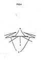
- the generally straight line portion 6, 61, 62, 63, 64 adjacent to the left or right side of the connection portion 5, 5A, 5B is connected in the form of a generally straight line (i.e., at a connection angle of 0°).
- the curve angle can be adjusted in the connection portion 5, 5A, 5B with a higher degree of freedom, which is more effective against kinking that occurs after a long period of time.
- Fig. 4 shows an embodiment in which the connection portion 5 and the generally straight line portion 6 are connected to each other at a connection angle ⁇ of 8°.
- connection portion 5, 5A, 5B in Figs. 1 and 2 is shown as a straight line, the connection portion shall not be limited thereto, and it may be a curved line.
- the above curved line stands for a line having at least one curved portion and includes a substantially S-letter-shaped line.
- the connection portion 5, 5A, 5B and the generally straight line portion 6, 61, 62, 63, 64 are bonded to each other by known bonding means such as welding, brazing (welding), calking, or the like.
- bonding means such as welding, brazing (welding), calking, or the like.
- the connection may be made by calking with a pipe unit to be described later.
- the central curved portion 8, 8A, 8B is formed in the form of a substantial R as shown in Figs. 1 to 3 (or as shown in Figs. 8 and 10 to be discussed later), while it may be formed in some other form such as a ring or the like.
- adjacent annular units are connected to each other with at least two connection portions 5, 5A, 5B above, and these connection portions are disposed (arranged) with a space between them. That is, as shown in Figs. 1 and 2 , the annular units are arranged with a space of at least one central curved portion 8, 8A, 8B (generally a space of 1 to 4 central curved portions) constituting the above zigzag patterns 7.
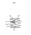
- Fig. 2 shows an embodiment in which the annular units 4A and 4B are connected with the connection portions 5A and 5B, and it can be understood that two central curved portions 8A and two central curved portions 8B are arranged or placed between the connection portions 5A and 5B.
- the stent 1 of the present invention has a configuration curved along the longitudinal direction thereof. Accordingly, angles ( ⁇ i ') at which those lines of the annular units constituting the stent, drawn in the radius directions of the stent, cross each other, increases with an increase in the number (n i ) of the central curved portions 8A, 8B arranged between the connection portions 5A and 5B, that is, n 1 ⁇ n 2 ⁇ n 3 , and thereby the relationship of ⁇ 1 ⁇ 2 ⁇ 3 holds.
- the degree of curve angle (degree of curvature) of the above adjacent annular units 4A and 4B (4C, 4D, 4E) in the longitudinal direction of the stent can be adjusted, wherein the angles ( ⁇ i ) are the angles at which those lines of the annular units constituting the stent which are drawn in the radius directions of the stent cross each other and the number (n i ) is the number of the central curved portions 8A, 8B arranged between the connection portions 5A and 5B.
- Fig. 1 shows the case wherein the connection portions 5 having the same lengths each, the degree of curve angle (degree of curvature) of the above adjacent annular units 4A and 4B (4C, 4D, 4E) in the longitudinal direction of the stent can be adjusted by changing the length of connection portions 5, 5A and 5B.
- the ratio ⁇ is less than 0.1, it is difficult to adjust the angles between the annular units 4, 4A and 4B.
- the length ratio ⁇ exceeds 2.0, undesirably, the stent may produce kinking after a long period of time or the expansion strength of the connection portions 5, 5A and 5B decreases.
- the number of the zigzag patterns may be changed as required for improving the stent in flexibility.
- at least one annular unit 4A, 4B having an odd number of the zigzag patterns 7 and at least one annular unit 4A, 4B having an even number of the zigzag patterns 7 are provided, and these are combined as required for constituting the stent 1.
- the annular units 4A, 4B having an odd number of the zigzag patterns 7 and the annular units 4A, 4B having an even number of the zigzag patterns 7 are arranged to be adjacent to each other and alternately placed in the longitudinal direction of the stent 1.
- one of the above annular units 4A and 4B adjacent to each other is constituted of an odd number (e.g., 7, 9, 11 or the like) of the zigzag patterns 7, and the other is constituted of an even number (e.g., 8, 10, 12 or the like) of the zigzag patterns 7.
- the annular units 4A, 4B having both an odd number (7, 9, 11) of the zigzag patterns 7 and the annular units 4A, 4B having both an even number (8, 10, 12) of the zigzag pattern 7 are alternately arranged along the longitudinal direction of the stent 1.
- stent 1 of the present invention contact of the zigzag patterns of the adjacent annular units can be prevented and arranged to overlap during expansion, so that a sharp curved configuration can be secured.
- the reason therefor is as follows. As shown in Figs. 1 to 3 , when the stent 1 is viewed from the outermost curved line R side of the stent 1 in a state where the stent 1 has a configuration curved in the longitudinal direction of the stent 1, 1 to 4 central curved portions 8, 8A, 8B constituting the zigzag patterns 7 are arranged between the two connection portions 5, 5A, 5B between the annular units 4A and 4B adjacent to each other and are opposed to each other (see Fig. 2 , when the Fig.
- the central curved portions 8, 8A, 8B of the zigzag patterns 7 constituting one of the annular units 4A and 4B adjacent to each other and the inside spaces 9 of the zigzag patterns 7 constituting the other are arranged substantially to be opposed to each other when the stent 1 is viewed from the innermost curved line R' side of the stent 1 (see Fig. 3 , when Fig. 1 is viewed from the Y side).
- the stent of the present invention is thus constituted, the zigzag patterns 7 can overlap, without contacting, the adjacent zigzag patterns 7 during expansion, and the configuration of the curved line R can be adjusted to take a sharper curve.
- the annular units 4A, 4B, 4C, 4D and 4E having respectively, 9, 10, 9, 10 and 9 zigzag patterns 7 are connected.
- Fig 1 to 3 show an embodiment of the stent 1 of the present invention in which annular units 4A, 4B having an odd number of the zigzag patterns 7 and annular units 4A, 4B having an even number of the zigzag patterns 7 are adjacent to each other and arranged alternately in the longitudinal direction of the stent 1 as described above for forming a structure of the stent more adaptable to the curved portion of a diseased part, that is, an arrangement pattern of odd number even number odd number - even number ⁇ ⁇ ⁇ is made.
- the other arrangement pattern may also be employed.
- a diseased part includes a diseased part (blood vessel) having the form of a straight line or a generally straight line
- a diseased part blood vessel having the form of a straight line or a generally straight line
- the stent 1 of the present invention is formed such that the ratio (contract ratio) of the contracted diameter of the generally tubular body, when inserted to a diseased part such as an aneurysm, or the like to the unloaded diameter of the generally annular body is between 20 % to 90 %.
- a diseased part blood vessel
- the stent of the present invention is thus diameter-contracted as required thereby to exert a higher radial force against a diseased part, so that the initial leak of blood to a swelling wall, including the leak immediately after the treatment, can be reliably stopped.
- the contract ratio is too large (less than 20 %), or too small (over 90 %), undesirably; the above desired radial force is not exerted
- the metal wire base material for forming the stent 1 of the present invention is not specially limited, and the stent 1 is formed from a wire made of a metal generally used, such as stainless steel such as SUS316L or the like, a superelastic alloy such as a Ti-Ni alloy or the like, titanium, a titanium alloy, tantalum, a tantalum alloy, platinum, a platinum alloy, tungsten, a tungsten alloy, or the like
- the stent made of any one of the above metals may be surface-coated with biocompatible polymer materials such as polyurethane, polyvinyl pyrrolidone, polyvinyl alcohol, or the like, with physiologically active substances such as heparin, urokinase or the like immobilized to the above coated polymer materials by chemical bonding, or with antithrombotic drugs such as argatroban, cilostazol, sarpogrelate HCl, or the like mixed to the above coated polymer materials.
- biocompatible polymer materials such as polyurethane, polyvinyl pyrrolidone, polyvinyl alcohol, or the like
- physiologically active substances such as heparin, urokinase or the like immobilized to the above coated polymer materials by chemical bonding, or with antithrombotic drugs such as argatroban, cilostazol, sarpogrelate HCl, or the like mixed to the above coated polymer materials.
- the stent graft constituted of the above stent, provided by the present invention, will be explained with reference to Figs. 5 and 6 hereinafter.
- the stent graft 11 of the present invention comprises the stent 1 and a tubular member 12 made of a synthetic resin, wherein the stent being covered with the tubular member 12.
- the stent graft 11 is used for repairing a blood vessel damaged by a stenosis, an aneurysm or the like or used as a replacement for a hollow organ.
- Fig. 5 is a schematic drawing of the stent graft 11 of the present invention, and it shows a state wherein the stent 1 shown in Fig. 1 is contracted to a size, the size with which the stent 1 inserted in a diseased part, and the stent 1 is circumferentially covered with a tubular member 12 (also called "graft") (indicated by a dotted line) made of a synthetic resin.
- a tubular member 12 also called "graft”
- Fig. 6 is a schematic drawing showing a state where the stent 1 is loaded into a sheath 10 having a curved forward end
- Fig. 7 is a schematic drawing showing a state wherein the stent 1 is loaded in a sheath 20 having a straight-line forward end.
- the tubular member (graft) made of a synthetic resin is fitted to the outside of the stent 1 and is diameter-contracted in conformity with the form of the stent 1, while Figs. 6 and 7 omit showing its diameter-contraction).
- the stent graft 11 can be manufactured by covering the above stent 1 with the tubular member 12 made of Dacron (polyethylene terephthalate fiber, E.I. du Pont de Nemours and Company, trade name), a film made of a fluorine resin (PTFE: polytetrafluoroethylene), or the like.
- Dacron polyethylene terephthalate fiber, E.I. du Pont de Nemours and Company, trade name
- PTFE polytetrafluoroethylene
- a stent having a diameter of 40 mm under no load is provided and contracted to 30 mm (75 %), a tubular member made of Dacron, having a diameter of 31 mm, sutured at end portion and any portion with a suture thread is covered and fixed on/to the above stent, whereby the stent graft 11 can be manufactured.
- the stent 1 that has a spring function and has good flexibility is covered with the tubular member 12 made of a synthetic resin in the form of a fiber or a film, so that the stent graft 11 can conform, as a stent graft, to the three-dimensional curve of a blood vessel as required.
- both ends of the stent 1 may have different diameter(s) depending upon a diseased part (blood vessel).
- annular units 4A, 4B having different diameters each are combined in conformity with the form of a diseased part (blood vessel), and the stent graft 11 is manufactured in conformity with the form thereof.
- the stent graft 11 can be adapted thereto by bringing the diameters of the annular units 4A, 4B forming both ends thereof into conformity with the form of the diseased part (blood vessel).
- the stent is designed initially and normally to be in a curved state easily adaptable to a curved blood vessel in a diseased part, so that there can be provided the stent 1 having excellent conformity to a curved portion of the main artery of a patent.
- the stent, etc., of the present invention can have a curved form without increasing the length of the connection portion 5, 5A, 5B between the annular units 4A and 4B, and it does not easily undergo kinking or deformation, so that it does not move even when it is anchored or left in a diseased part for a long period of time.
- Figs. 8 to 11 are drawings showing a stent in which a pipe unit that exhibits the function of reinforcement, sustained release of a drug, or the like is fitted to the stent main line made of a metal line wire base material
- Fig. 8 is a drawing for explaining a state wherein two annular units are connected to each other with connection struts to form a stent and the connected stent is provided with pipe units.
- Fig. 9 is a drawing for explaining a structure of a welded portion as a change in the stent main line.
- Fig. 10 is a drawing for explaining a state wherein an X ray impermeable portion is protected with a pipe.
- Fig. 11 is a drawing for explaining a state wherein a pipe charged with a drug and sealed is attached.
- Fig. 12 is a drawing for explaining a state wherein a hook is connected to the stent main line with a pipe.
- the other working embodiment of the present invention has a characteristic feature in that a pipe unit is fitted to the stent main line to cause the stent to exhibit the various functions of reinforcement, sustained release of a drug, and the like.
- the targeted stent, to which the pipe unit for imparting the above functions is most effectively applied, is naturally, and in the first principle, to the stent having a curved configuration in the longitudinal direction in a stationary or normal state as shown in Fig. 1 .
- the technical feature or idea thereof is not limited thereto and can be applied to a more general stent. The following explanation therefore includes an explanation with regard to a general stent.
- the stent with a pipe unit is a stent A' that is generally a tubular body comprising generally annular units 2' formed by bonding end portions of a stent main line 1' made of a metal line wire base material formed in a zigzag form and connection struts 4' connecting said annular units 2' in series, wherein a pipe unit 3' being inserted and fitted to a changed portion of the stent main line 1' and/or the connection strut 4' in said annular unit 2' and fixed to said stent main line 1', or wherein a pipe unit 5', 7' being fitted to that portion of the stent main line 1' which is provided with an element different from the stent main line 1' and/or the strut 4' in said annular unit 2', thereby causing the stent to exhibit at least one of functions for reinforcement, sustained release of a drug and marker protection.
- the above mentioned change of the stent main line, etc. includes a change in diameter and a change in structure, and for example, it means that site of the stent main line or the strut, at which site its diameter is reduced, for connection of strut to the stent is to be arranged along the stent main line, and a portion or site that comes to have coarse-particle-structure due to heat or thermal effect caused by welding both ends of the stent main line or welding end portions of the stent main line and that of the strut.
- the pipe unit is arranged and fixed to the above site for reinforcement as will be described later.
- the element different from the stent main line, etc. means solid substances such as an X ray impermeable portion (X ray imaging marker such as a plating, a foil, etc.) formed in the stent main line or the connection strut, or a solid drug.
- the pipe unit is arranged and fixed so as to be opposed or faced thereto as will be described later, so that it can prevent a plating or foil constituting the above X ray impermeable portion from coming off, and that it can prevent these substances from entering in blood stream even when the substances come off.
- the stent A' shown in Fig. 8 is formed of annular units as described already. Specifically, the stent main line (wire base material made of a metal) 1' is bent in a predetermined zigzag form (zigzag patterns), and both ends of the stent main line 1' are faced and bonded to each other by welding to form an annular unit (which is sometimes referred to as "loop") 2.
- a pipe unit 3' for reinforcement is arranged in the above welded portion to reinforce it, further, a plurality of such annular units 2' (two annular units here) are arranged in series, at least two connection struts 4' and 4' are disposed between the adjacent annular units 2', the adjacent annular units (stent main lines thereof) are fixed and connected with the above connection struts 4' preferably by welding, and the welded portions are reinforced with pipe units 5'.
- the stent main line 1' there is used a material such as generally provided austenitic stainless steel or a wire material of SUS316L particularly provided as a stainless steel for implants as described already. And these stainless wire material materials are subjected to cold wire drawing so that the structure thereof is extended in the form of fibers (fibrous structure), thereby causing the material to exhibit work hardening to improve its mechanical properties.
- the stent formed of the above material has excellent biocompatibility and has proper expendability, and, therefore, when it is released from the sheath in an intended diseased part, it easily restores the initial form. Further, the above material has strong resistance against age-deterioration, so that it is suitable for anchoring or leaving the stent in a diseased part in a human body for a long period of time.
- the annular unit is formed by bonding end portions of the stent main line (wire base material made of a metal) made of stainless steel having excellent properties to each other by welding. In this case, however, the following problem of a decrease in the strength of the welded portion can occur.
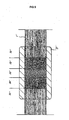
- Fig. 9 is a drawing for explaining a change in the structure of metal in the welded portion of the stent main line when the end portions of the stent main line 1' formed in a zigzag form are cause to face each other and resistance-welded to form the annular unit.
- the metal structure in a welded region 1a' formed mainly of butt ends, the metal structure is caused to be coarse due to welding heat and comes to be granulated, and the strength thereof as a wire base material of the stent main line is greatly decreased.
- regions 1b' and 1b' outside the above area are affected by the welding heat to some extent, so that the metal structure thereof is caused to granulate, and a decrease in strength also occurs in these regions.
- Regions 1c' and 1c' outside them are regions that do not substantially suffer the heat effect of welding, and the original structure in the form of extended fibers remains intact and maintains the strength inherent to the wire base material.
- a pipe unit 3' is arranged, for reinforcement, in those portions of the welded portion of the stent main line 1' which include the welded region 1a' as a center and the regions 1b', 1b', which suffer a relatively large decrease in strength as compared with the areas 1c', 1c', thereby securing the strength inherent to the annular unit 2'.
- the pipe unit 3' that has a length capable of covering at least the region 1a' up to the regions 1c', 1c' on both sides thereof is inserted and fitted to the stent main line 1' as shown in Fig. 9 , and in this position, both end portions of the above pipe unit 3' are calked to fix and integrate the pipe unit 3' to/with the stent main line 1.
- the above pipe unit 3' for reinforcement, thus applied, can reinforce that site of the metal structure which is decreased in strength by suffering from the welding heat.
- the size (length) of the welded region 1a' and the regions 1b' in the annular unit 2' is not uniquely determined and takes a value that differs depending upon the diameter of the stent main line 1' used.
- the above length is not so great, and in any case, it is on the unit of several millimeters at the greatest.
- the pipe unit 3' has a length of approximately 1 mm.
- the pipe unit 3' may have a length of 7 mm by taking into account of a calking margin, and it is practical to use a cylindrical pipe having an outer diameter of approximately 0.65 mm and an inner diameter of approximately 0.46 mm.
- the material of the pipe unit 3' is not specially limited, it is preferred to use a pipe made of the same material as that of the stent, such as SUS316L provided as a stainless steel for implants, since it is anchored or left in a diseased part together with the stent for a long period of time.
- a pipe made of the same material as that of the stent such as SUS316L provided as a stainless steel for implants, since it is anchored or left in a diseased part together with the stent for a long period of time.
- an austenitic stainless steel having an extended fibrous structure, or the like is used for the stent main line 1', and the pipe unit 3' for reinforcement is arranged and calked in a welded site of the annular unit 2' formed by welding end portions of the stent main line 1', whereby reinforcement can be made with the welded site of the above annular unit.
- connection portion (welded portion) of the annular unit and the connection member (connection strut) can be reinforced with a pipe unit 5' as shown in Fig. 8 .
- the pipe unit 5' for reinforcement which is to reinforce the connection portion (welded portion) of the stent main line 1' constituting the annular unit 2' and the connection strut 4', is inserted and fitted to the stent main line 1' after the stent main line 1' is formed into the zigzag patterns but before the end portions are welded (before the annular unit is formed). It is therefor required to pass the pipe unit 5' through the peak portion(s) (central curved portions) 1d' of the zigzag pattern(s).
- the above portion 1d' has the form of generally or substantially R or a ring as shown in Fig. 10 .
- the pipe unit is designed to have such small dimensions that said pipe unit can easily pass through the above peak portion 1d' with regard to its length, and a plurality of such pipe units 5' (generally, about 3 pipe units) are arranged in each connection portion.
- the pipe unit 5' is preferably designed to have a length that is three times as long as the diameter of the stent main line 1' or less. According to the present inventors' finding, when the stent main line 1' has a diameter of 0.45 mm, and if the pipe unit 5' has a length of approximately 0.98 mm, working can be most smoothly carried out. On the other hand, it has been found that if the length is smaller than 0.5 mm, it is difficult to secure smooth workability.
- the pipe unit is fitted to that portion of the stent main line of the stent A' at which is to be provided with the element different from the connection strut, the different element being such as a drug or an X ray imaging marker, thereby the stent A' can perform the above function for marker protection, sustained release of a drug, or the like.
- the stent is delivered to a diseased part (blood vessel) while monitoring the stent position, it is preferred to form an imaging marker such as an X ray impermeable portion 6' or the like at some part of the stent main line 1'.
- an imaging marker such as an X ray impermeable portion 6' or the like
- a metal material or inorganic material, an X ray impermeable material having a specific gravity of 8 or more is caused to adhere or fixed to part of a long line of a zigzag pattern, a foil thereof is attached thereto, or a thin film thereof is formed thereon, as a marker.
- X ray impermeable material examples include gold, silver, platinum, tungsten, barium, molybdenum, tantalum, iridium, bismuth and oxides, carbides, nitrides, borides, etc., of these.
- the means of forming a thin film of any of these can be selected as required depending upon each metal, etc., and there can be applied any means such as plating, sputtering, reactive sputtering, vacuum vapor deposition, bonding of a thin film thereof (gold foil, etc.), pressure-bonding, or the like.
- connection strut 4' it is relatively easy to apply gold plating or a gold foil to an end portion of the relatively short and generally straight-shaped connection strut 4', so that the X ray impermeable portion 6' is formed in a predetermined-range (such a length that can be covered with the length of pipe unit 5') in an end portion of the connection strut 4' by plating gold.
- the X ray impermeable portion 6' may be any portion so long as the position of the stent A' can be reliably monitored with X ray imaging, and particulars thereof shall not be limited. According to the finding of the present inventors, when the stent main line 1' has a diameter of 0.45 mm and the connection strut 4' has a diameter of 0.35 mm, and if a gold plate having a thickness of 2 ⁇ m is formed in a range of 3.5-mm to 4 mm, the monitoring of the position can be reliably made with X ray imaging.
- the pipe unit 5' has a length of approximately 1 mm, and 5 to 6 pipe units 5' are arranged side by side by connection and calked, thereby covering of the X ray impermeable portion 6' and the connection of stent main line 1' and the strut 4' can be both provided.
- connection strut 4' When the annular units 2' are connected with the connection strut 4', the end portion of the connection strut 4' on which the X ray impermeable portion 6' is formed is arranged along the stent main line 1', and a plurality of the pipes 5' are inserted and fitted them and calked, whereby the X ray impermeable portion 6' can be covered and protected with the pipes 5'. Further, when the stent A' is anchored or left in a diseased part, the X ray impermeable portion 6' is not exposed directly to a blood flow.
- connection strut 4' with the X ray impermeable portion 6' formed thereon is connected to the stent main line 1' constituting the annular unit 2', preferably, the position to which the gold plating or gold foil is applied is in the vicinity of the peak portion (central curved portion) 1d' of the annular unit 2' so that the passageway through which the stent A' reaches a diseased part can be reliably monitored by X ray imaging.
- an anti-thrombosis drug is externally administered.
- the drug can be fitted to the stent A' inserted in a blood vessel and gradually released from the stent directly into blood at an intended place, advantageously, the effect of the drug can be more effectively produced.
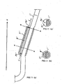
- a relatively long pipe unit 7' is used as shown in Fig. 11(a) , a powder, preferably fluid drug 8', is charged into the pipe unit 7' and sealed, and the pipe unit is fitted and arranged to/on the stent main line 1'.
- a drug 8' an optimum one is selected in advance depending upon a patient to be treated and an operation method employed and charged into the pipe unit 7'.
- Fig. 11(b) is a cross sectional view taken along line a-a in Fig. 11(a)
- Fig. 11(c) is a cross sectional view taken along line b-b in Fig. 11(a) .
- the pipe unit 7' has a very small hole portion 7a' formed in a predetermined position (e.g., a position that permits a contact with blood flow, such as an end surface or a side surface), the drug comes in contact with blood, which enters and flows away through the above hole portion 7a', and the drug can be dissolved gradually in the blood and released.
- a predetermined position e.g., a position that permits a contact with blood flow, such as an end surface or a side surface
- the pipe unit 7' for sealing a drug therein and gradually releasing it is formed generally to be relatively long. Therefore, even when attempts are made to fit and arrange the above pipe unit 7' after the stent main line 1' is formed in zigzag patterns, it is difficult to pass the pipe unit 7' through the peak portion (central curved portion) 1d'. It is thus preferred to arrange the pipe unit 7' in the straight line portion in the vicinity of a welded area of the stent main line 1'.
- the stent main line 1' is shaped in a form including a semicircular at cross section beforehand as shown in Fig. 11(b) , and the pipe unit 7' is arranged in the thus shaped portion.
- the pipe unit 7' is fixed to the stent main line 1' by calking both ends thereof.
- the stent A' is fitted with the pipe unit charged with a drug such as a thrombolytic agent, or the like, whereby the stent A', when anchored or left in a diseased part, can itself exhibit an action of effective DDS (Drug Delivery System) (sustained release system) without carrying out any special external blood transfusion or administration such as an injection or the like.
- a drug such as a thrombolytic agent, or the like
- a hook 11' for gripping a guide wire 10' which is arranged through the sheath when the stent A' is anchored in a diseased part, is arranged as an element different from the stent main line 1' and the strut 4' will be explained with reference to Fig. 12 .
- the hook 11' is caught on a notched portion 14a' formed in a dilator 14', and when the sheath 13' is moved backward after the dilator 14' is fixed in a diseased part, the hook 11' works to discharge the stent A' housed in the above sheath 13'.
- the hook 11' is formed, for example, using a wire material of an austenitic stainless steel like the connection struts 4'.
- the stent A' is covered with a cylindrical graft 12', and the stent A' is diameter-contracted in conformity with the internal diameter of the sheath 13' and is housed in the sheath 13'.
- the dilator 14' is housed in the sheath 13', and further, the guide wire 10' having a top portion externally exposed is housed in the dilator 14'.
- an operation portion at hand that is not shown is operated, to fix a forward end loop 2' at an intended diseased part with the dilator 14', and in this state, the sheath 13' is withdrawn toward the operator side, thereby the stent A' is discharged from the sheath 13, expanded and anchored in the diseased part.
- the hook 11' for example, one wire material made of an austenitic stainless steel is curved, both ends thereof are arranged along the stent main line 1', the pipe unit 5' is disposed, and the hook 11' is fitted to the annular unit 2' integrally with the stent main line 1' and the pipe unit 5', by simultaneously calking them.
- a gold plating or gold foil is applied to those two ends of the hook 11' which are attached to the stent main line 1', thereby forming an imaging marker such as the X ray impermeable portion 6'.
- the X ray impermeable portion 6' can be covered and protected with the pipe unit 5' as discussed already.
- the welded portion can be covered with the pipe unit 5' and can be reinforced by calking.
- the pipe unit is fitted and fixed to that portion of the stent main line and/or the connection strut which suffers a change in metal structure due to welding heat and is decreased in strength as explained already, thereby the thus-changed stent main line and/or connection strut can be reinforced.
- the pipe unit is arranged and fixed to such a portion of the stent main line at which metal structure comes to have coarse particles due to heat effect caused by welding ends of the stent main line, thereby this portion can be reinforced with the above pipe unit.
- the pipe unit is arranged and fixed to face a solid element as a function-imparting element different from the stent main line and the connection strut, for example, the X ray impermeable portion formed on the stent main line or the connection strut, thereby said fixed pipe unit can prevent the gold plating or gold foil constituting the above X ray impermeable portion from coming off, and prevent such a substance from, in the least, entering the blood flow even if it comes off.
- the pipe unit charged with a fluid for example, a drug such as a liquid or powder containing an anti-thrombosis drug and sealed
- a fluid for example, a drug such as a liquid or powder containing an anti-thrombosis drug and sealed
- the above drug sealed therein is maintained, and hole portion(s) opened to an inside thereof is (are) formed in predetermined position(s) of the above pipe unit, thereby the drug can be dissolved in the blood flow and can be gradually released.
- the pipe unit is selectively imparted with the function of protection, the function of protecting an X ray marker, the function of sustained release of a drug, or the like, thereby a multi-purpose stent can be provided.
Landscapes
- Health & Medical Sciences (AREA)
- Engineering & Computer Science (AREA)
- Biomedical Technology (AREA)
- Cardiology (AREA)
- Oral & Maxillofacial Surgery (AREA)
- Transplantation (AREA)
- Heart & Thoracic Surgery (AREA)
- Vascular Medicine (AREA)
- Life Sciences & Earth Sciences (AREA)
- Animal Behavior & Ethology (AREA)
- General Health & Medical Sciences (AREA)
- Public Health (AREA)
- Veterinary Medicine (AREA)
- Gastroenterology & Hepatology (AREA)
- Pulmonology (AREA)
- Media Introduction/Drainage Providing Device (AREA)
- Prostheses (AREA)
Abstract
Claims (10)
- Stent (1), qui est conçu en forme de corps généralement tubulaire possédant un axe central (C) et qui assure une fonction élastique, grâce à laquelle le corps tubulaire peut être contracté en diamètre dans la direction de son axe central (C), et étendu, après la contraction, jusqu'au diamètre initial, le stent étant chargé et logé dans une gaine et introduit dans une partie malade à traiter,(A) le stent (1) conservant une configuration courbée dans son sens longitudinal, lorsqu'il n'est pas inséré dans la gaine,(B) le stent(1) étant contracté en direction de son axe central (C) et allongé en forme de ligne généralement droite dans son sens longitudinal, lorsqu'il est inséré dans la gaine, ce qui l'amène à être chargé et logé dans la gaine en forme de ligne généralement droite,(C) et le stent (1) étant, en état logé dans la gaine en forme de ligne généralement droite, introduit dans une partie malade avec la gaine, puis dégagé de celle-ci, dégagement, après lequel il s'étend radialement à l'extérieur, afin de restaurer et de conserver la configuration courbée dans son sens longitudinal, et le stent(1) comporte des motifs en zigzags (7) généralement en forme de V ayant au moins une portion centrale courbée (8, 8A, 8B) constituant le motif en zigzag et, de part et d'autre de celle-ci, des portions généralement en forme de ligne droite (6, 61, 62, 63, 64) essentiellement de même longueur, les motifs en zigzag (7) étant réalisés en pliant à plusieurs reprises une portion entre deux extrémités d'un matériau de base en fil métallique, une multitude de ces motifs en zigzag (7) étant disposée de façon à entourer l'axe central (C) du stent (1), une unité annulaire (4A, 4B, 4C, 4D, 4E) étant réalisée en reliant les portions d'extrémité de ce fil métallique de façon à obtenir une seule portion, et une multitude d'unités annulaires de ce genre (4A, 4B, 4C, 4D, 4 E) est constituée, une multitude de ces unités annulaires (4A, 4B, 4C, 4D, 4 E) constituée est disposée en séries dans le sens longitudinal (direction de l'axe central) du stent (1),caractérisé en ce que(a) ces unités annulaires (4A, 4B, 4C, 4D, 4 E), adjacentes les unes aux autres, sont reliées les unes aux autres à l'aide d'au moins deux entretoises de raccordement qui forment les portions de liaison (5, 5A, 5B),(b) qu'entre ces au moins deux entretoises de raccordement ou portions de liaison (5, 5A, 5B) un espace ou une ou plusieurs portions centrales courbées (8, 8A, 8B) constituant les motifs en zigzag (7) sont aménagés, l'espace ou le nombre de portions centrales courbées étant varié de manière à obtenir la configuration telle qu'elle est définie sous (A) ou (C),(c) et que, plus l'espace ou le nombre des portions centrales courbées (8, 8A, 8B) entre les portions de liaison (5, 5A, 5B) est grand, plus le degré de courbure de la configuration courbée est élevé ou plus les angles (8), formés entre celles des lignes tirées dans les sens du rayon des unités annulaires (4A, 4B, 4C, 4E) constituant le stent (1), sont grands.
- Stent (1), tel que spécifié à la revendication 1, dans lequel l'entretoise de raccordement a au moins une unité annuaire (4A, 4B, 4C, 4D, 4 E), qui présente un nombre impair de motifs en zigzag (7), et au moins une unité annulaire (4A, 4B, 4C, 4D, 4 E), qui présente un nombre pair de motifs en zigzag (7).
- Stent (1), tel que spécifié à la revendication 1 ou 2, dans lequel les unités annulaires (4A, 4B, 4C, 4D, 4E) présentant un nombre impair de motifs en zigzag (7) et les unités annulaires (4A, 4B, 4C, 4D, 4E) présentant un nombre pair de motifs en zigzag (7) sont disposées de manière qu'elles soient adjacentes les unes aux autres et agencées alternativement dans le sens longitudinal du stent (1).
- Stent (1), tel que spécifié à une quelconque des revendications 1 à 3, dans lequel, le stent (1) étant dans un état, dans lequel il conserve une configuration courbée dans son sens longitudinal, au moins 1 à 4 portions centrales courbées (8, 8A, 8B) constituant le motif en zigzag (7) et au moins 1 à 4 portions centrales courbées constituant le motif en zigzag (7) sont disposées de manière qu'elles soient essentiellement opposées les unes aux autres entre deux portions de liaison (5, 5A, 5B), entre deux unités annulaires (4A, 4B, 4C, 4D, 4 E), lorsqu'elles sont vues depuis le côté de la ligne courbée R la plus à l'extérieur du stent(1), et les portions centrales courbées (8, 8A, 8B) du motif en zigzag (7) constituant une des unités annulaires (4A, 4B, 4C, 4D, 4 E) adjacentes les unes aux autres et les espaces intérieurs (9) des motifs en zigzag (7) de l'autre des unités annulaires (4A, 4B, 4C, 4D, 4E) étant disposés de manière que ces portions centrales courbées (8, 8A, 8B) et ces espaces intérieurs (9) soient essentiellement opposés les uns aux autres, lorsqu'ils sont vus depuis le côté de la ligne courbée R' la plus à l'intérieur du stent (1).
- Stent (1), tel que spécifié à une quelconque des revendications 1 à 4, dans lequel les portions de liaison (5, 5A, 5B) sont en forme de ligne droite ou de ligne courbée.
- Stent (1), tel que spécifié à une quelconque des revendications 1 à 5, dans lequel la portion de liaison (5, 5A, 5B) présente une longueur S, la portion généralement en forme de ligne droite (6, 61, 62, 63, 64) présente une longueur L et la portion de liaison (5, 5A, 5B) et la portion généralement en forme de ligne droite (6, 61, 62, 63, 64) possèdent un rapport longueur φ (=S/L) de 0,1 à 2,0.
- Stent (1), tel que spécifié à une quelconque des revendications 1 à 6, dans lequel la portion centrale courbée (8, 8A, 8B) présente une forme généralement en R ou annulaire.
- Stent (1), tel que spécifié à une quelconque des revendications 1 à 7, dans lequel le corps généralement tubulaire, en état non chargé, est contracté en diamètre de 20% à 90% lorsqu'il est introduit dans une partie malade.
- Stent (1), tel que spécifié à une quelconque des revendications 1 à 8, dans lequel un élément tubulaire ayant au moins une fonction de renforcement, de protection de marqueur et de délivrance prolongée d'un médicament est monté sur le matériau de base en fil métallique qui constitue le stent.
- Greffe de stent formée en recouvrant le stent (1) spécifié à une quelconque des revendications 1 à 9 d'un élément tubulaire (12) réalisé en résine synthétique.
Applications Claiming Priority (5)
| Application Number | Priority Date | Filing Date | Title |
|---|---|---|---|
| JP2002144076 | 2002-05-20 | ||
| JP2002144076A JP4064724B2 (ja) | 2002-05-20 | 2002-05-20 | ステント及びステントグラフト |
| JP2002261519 | 2002-09-06 | ||
| JP2002261519A JP4298244B2 (ja) | 2002-09-06 | 2002-09-06 | ステント |
| PCT/JP2003/006190 WO2003097155A1 (fr) | 2002-05-20 | 2003-05-19 | Stent et greffe de stent |
Publications (3)
| Publication Number | Publication Date |
|---|---|
| EP1506793A1 EP1506793A1 (fr) | 2005-02-16 |
| EP1506793A4 EP1506793A4 (fr) | 2008-05-21 |
| EP1506793B1 true EP1506793B1 (fr) | 2009-08-05 |
Family
ID=29552307
Family Applications (1)
| Application Number | Title | Priority Date | Filing Date |
|---|---|---|---|
| EP03730507A Expired - Lifetime EP1506793B1 (fr) | 2002-05-20 | 2003-05-19 | Stent et greffe de stent |
Country Status (6)
| Country | Link |
|---|---|
| US (1) | US7794492B2 (fr) |
| EP (1) | EP1506793B1 (fr) |
| AU (1) | AU2003242316B2 (fr) |
| DE (1) | DE60328677D1 (fr) |
| ES (1) | ES2330627T3 (fr) |
| WO (1) | WO2003097155A1 (fr) |
Families Citing this family (35)
| Publication number | Priority date | Publication date | Assignee | Title |
|---|---|---|---|---|
| EP1725188A1 (fr) * | 2004-03-02 | 2006-11-29 | Boston Scientific Scimed, Inc. | Dispositifs medicaux comprenant des films metalliques et leurs methodes de fabrication |
| WO2005099806A1 (fr) * | 2004-04-16 | 2005-10-27 | Kawasumi Laboratories, Inc. | Dispositif d’endoprothèse couverte à demeure |
| WO2008013042A1 (fr) * | 2006-07-25 | 2008-01-31 | Mani, Inc. | Stent |
| US20110230958A1 (en) * | 2006-07-25 | 2011-09-22 | Mani, Inc. | Stent |
| CN101500516B (zh) * | 2006-08-02 | 2011-08-24 | 马尼株式会社 | 支架 |
| GB0617219D0 (en) * | 2006-08-31 | 2006-10-11 | Barts & London Nhs Trust | Blood vessel prosthesis and delivery apparatus |
| US8545548B2 (en) | 2007-03-30 | 2013-10-01 | DePuy Synthes Products, LLC | Radiopaque markers for implantable stents and methods for manufacturing the same |
| US20140094901A1 (en) * | 2007-03-30 | 2014-04-03 | DePuy Synthes Products, LLC | Radiopaque marker for vascular devices |
| US9226813B2 (en) | 2007-12-26 | 2016-01-05 | Cook Medical Technologies Llc | Low profile non-symmetrical stent |
| GB2475494B (en) | 2009-11-18 | 2011-11-23 | Cook William Europ | Stent graft and introducer assembly |
| GB2476451A (en) * | 2009-11-19 | 2011-06-29 | Cook William Europ | Stent Graft |
| US8574284B2 (en) | 2007-12-26 | 2013-11-05 | Cook Medical Technologies Llc | Low profile non-symmetrical bare alignment stents with graft |
| US9180030B2 (en) | 2007-12-26 | 2015-11-10 | Cook Medical Technologies Llc | Low profile non-symmetrical stent |
| GB0803302D0 (en) * | 2008-02-22 | 2008-04-02 | Barts & London Nhs Trust | Blood vessel prosthesis and delivery apparatus |
| GB2464978B (en) * | 2008-10-31 | 2010-10-20 | Cook William Europ | Introducer for deploying a stent graft in a curved lumen |
| US8858610B2 (en) | 2009-01-19 | 2014-10-14 | W. L. Gore & Associates, Inc. | Forced deployment sequence |
| BRPI1014683B1 (pt) * | 2009-03-03 | 2020-01-07 | Mani, Inc. | Stent |
| US9757263B2 (en) | 2009-11-18 | 2017-09-12 | Cook Medical Technologies Llc | Stent graft and introducer assembly |
| GB201018869D0 (en) * | 2010-11-08 | 2010-12-22 | Isis Innovation | Curved stent graft assembly |
| US9744033B2 (en) | 2011-04-01 | 2017-08-29 | W.L. Gore & Associates, Inc. | Elastomeric leaflet for prosthetic heart valves |
| US10117765B2 (en) * | 2011-06-14 | 2018-11-06 | W.L. Gore Associates, Inc | Apposition fiber for use in endoluminal deployment of expandable implants |
| US9554806B2 (en) | 2011-09-16 | 2017-01-31 | W. L. Gore & Associates, Inc. | Occlusive devices |
| US9877858B2 (en) | 2011-11-14 | 2018-01-30 | W. L. Gore & Associates, Inc. | External steerable fiber for use in endoluminal deployment of expandable devices |
| US9782282B2 (en) | 2011-11-14 | 2017-10-10 | W. L. Gore & Associates, Inc. | External steerable fiber for use in endoluminal deployment of expandable devices |
| US9375308B2 (en) | 2012-03-13 | 2016-06-28 | W. L. Gore & Associates, Inc. | External steerable fiber for use in endoluminal deployment of expandable devices |
| US8968386B2 (en) | 2012-07-11 | 2015-03-03 | The Cleveland Clinic Foundation | Stent and method for maintaining the area of a body lumen |
| US11911258B2 (en) | 2013-06-26 | 2024-02-27 | W. L. Gore & Associates, Inc. | Space filling devices |
| US20160081823A1 (en) * | 2014-09-23 | 2016-03-24 | Cordis Corporation | Endoprosthesis with predetermined curvature formed by tri-tethers |
| US20180008394A1 (en) | 2015-01-12 | 2018-01-11 | Endospan Ltd. | Self-curving stent-graft |
| EP3294150B1 (fr) | 2015-05-14 | 2021-12-15 | W. L. Gore & Associates, Inc. | Dispositifs d'occlusion d'appendice auriculaire |
| AU2018230960B2 (en) | 2017-03-08 | 2020-07-09 | W. L. Gore & Associates, Inc. | Steering wire attach for angulation |
| JP2020512914A (ja) * | 2017-03-21 | 2020-04-30 | エンドスパン リミテッド | 外部擾乱の周りを密封するためのステントグラフト |
| US11173023B2 (en) | 2017-10-16 | 2021-11-16 | W. L. Gore & Associates, Inc. | Medical devices and anchors therefor |
| EP3843659A1 (fr) | 2018-08-31 | 2021-07-07 | W.L. Gore & Associates, Inc. | Appareil, système et méthode pour diriger un dispositif médical implantable |
| US12521260B2 (en) | 2018-08-31 | 2026-01-13 | W. L. Gore & Associates, Inc. | Releasable knots for medical device delivery |
Family Cites Families (22)
| Publication number | Priority date | Publication date | Assignee | Title |
|---|---|---|---|---|
| JPH01157020A (ja) * | 1987-12-14 | 1989-06-20 | Toshiba Corp | 真空開閉器 |
| CA2026604A1 (fr) * | 1989-10-02 | 1991-04-03 | Rodney G. Wolff | Drain articule |
| JPH04126557A (ja) | 1990-09-17 | 1992-04-27 | Kenzo Takahashi | ダブルドラム型非鉄金属分別装置 |
| JP2540719Y2 (ja) * | 1991-04-30 | 1997-07-09 | 株式会社パイオラックス | カテーテル |
| JP3151983B2 (ja) | 1992-12-25 | 2001-04-03 | 株式会社ノーリツ | 風呂給湯器 |
| US5609627A (en) * | 1994-02-09 | 1997-03-11 | Boston Scientific Technology, Inc. | Method for delivering a bifurcated endoluminal prosthesis |
| DE4418336A1 (de) * | 1994-05-26 | 1995-11-30 | Angiomed Ag | Stent |
| US5636641A (en) * | 1994-07-25 | 1997-06-10 | Advanced Cardiovascular Systems, Inc. | High strength member for intracorporeal use |
| BE1009278A3 (fr) * | 1995-04-12 | 1997-01-07 | Corvita Europ | Tuteur auto-expansible pour dispositif medical a introduire dans une cavite d'un corps, et dispositif medical muni d'un tel tuteur. |
| JP3938418B2 (ja) * | 1996-09-25 | 2007-06-27 | テルモ株式会社 | ステント |
| US6432127B1 (en) * | 1996-10-11 | 2002-08-13 | Transvascular, Inc. | Devices for forming and/or maintaining connections between adjacent anatomical conduits |
| WO1998020810A1 (fr) * | 1996-11-12 | 1998-05-22 | Medtronic, Inc. | Protheses intracavitaires souples radialement expansibles |
| US5827321A (en) * | 1997-02-07 | 1998-10-27 | Cornerstone Devices, Inc. | Non-Foreshortening intraluminal prosthesis |
| US6174330B1 (en) * | 1997-08-01 | 2001-01-16 | Schneider (Usa) Inc | Bioabsorbable marker having radiopaque constituents |
| DE19746882A1 (de) * | 1997-10-23 | 1999-04-29 | Angiomed Ag | Aufgeweiteter Stent und Verfahren zum Herstellen desselben |
| US6280467B1 (en) * | 1998-02-26 | 2001-08-28 | World Medical Manufacturing Corporation | Delivery system for deployment and endovascular assembly of a multi-stage stented graft |
| JP2001231868A (ja) * | 2000-02-25 | 2001-08-28 | Arata Ishimaru | ステント及びステントグラフト並びにステント構成部材 |
| US6572646B1 (en) * | 2000-06-02 | 2003-06-03 | Advanced Cardiovascular Systems, Inc. | Curved nitinol stent for extremely tortuous anatomy |
| US6554848B2 (en) * | 2000-06-02 | 2003-04-29 | Advanced Cardiovascular Systems, Inc. | Marker device for rotationally orienting a stent delivery system prior to deploying a curved self-expanding stent |
| JP2002035135A (ja) * | 2000-07-31 | 2002-02-05 | Manii Kk | ステント及びステントの製造方法 |
| US6774800B2 (en) * | 2001-03-30 | 2004-08-10 | Augmentech, Inc. | Patient incontinence monitoring apparatus and method of use thereof |
| JP4126557B2 (ja) | 2004-05-31 | 2008-07-30 | 株式会社デンソー | 電磁弁装置 |
-
2003
- 2003-05-19 DE DE60328677T patent/DE60328677D1/de not_active Expired - Lifetime
- 2003-05-19 ES ES03730507T patent/ES2330627T3/es not_active Expired - Lifetime
- 2003-05-19 AU AU2003242316A patent/AU2003242316B2/en not_active Ceased
- 2003-05-19 WO PCT/JP2003/006190 patent/WO2003097155A1/fr not_active Ceased
- 2003-05-19 EP EP03730507A patent/EP1506793B1/fr not_active Expired - Lifetime
- 2003-05-19 US US10/513,336 patent/US7794492B2/en not_active Expired - Fee Related
Also Published As
| Publication number | Publication date |
|---|---|
| DE60328677D1 (de) | 2009-09-17 |
| AU2003242316A1 (en) | 2003-12-02 |
| EP1506793A4 (fr) | 2008-05-21 |
| AU2003242316B2 (en) | 2005-12-15 |
| US20050240257A1 (en) | 2005-10-27 |
| WO2003097155A1 (fr) | 2003-11-27 |
| ES2330627T3 (es) | 2009-12-14 |
| US7794492B2 (en) | 2010-09-14 |
| EP1506793A1 (fr) | 2005-02-16 |
Similar Documents
| Publication | Publication Date | Title |
|---|---|---|
| US7794492B2 (en) | Stent and stent graft | |
| EP0824902B1 (fr) | Stent expansible | |
| US10687967B2 (en) | Stretchable stent and delivery system | |
| JP6110427B2 (ja) | 解剖学的開口部を密閉するシステム及び方法 | |
| US7081129B2 (en) | Endovascular graft | |
| US6491719B1 (en) | Tubular endoluminar prosthesis having oblique ends | |
| US6818013B2 (en) | Intravascular stent device | |
| US6673106B2 (en) | Intravascular stent device | |
| AU2021363179B2 (en) | Stent | |
| JP2004097382A (ja) | ステント | |
| JP5847160B2 (ja) | ステントおよびステントデリバリーシステム | |
| CA2358449A1 (fr) | Extenseurs intravasculaires tubulaires expansibles |
Legal Events
| Date | Code | Title | Description |
|---|---|---|---|
| PUAI | Public reference made under article 153(3) epc to a published international application that has entered the european phase |
Free format text: ORIGINAL CODE: 0009012 |
|
| 17P | Request for examination filed |
Effective date: 20041209 |
|
| AK | Designated contracting states |
Kind code of ref document: A1 Designated state(s): AT BE BG CH CY CZ DE DK EE ES FI FR GB GR HU IE IT LI LU MC NL PT RO SE SI SK TR |
|
| RBV | Designated contracting states (corrected) |
Designated state(s): DE ES FR GB IT SE |
|
| A4 | Supplementary search report drawn up and despatched |
Effective date: 20080421 |
|
| 17Q | First examination report despatched |
Effective date: 20080714 |
|
| GRAP | Despatch of communication of intention to grant a patent |
Free format text: ORIGINAL CODE: EPIDOSNIGR1 |
|
| GRAS | Grant fee paid |
Free format text: ORIGINAL CODE: EPIDOSNIGR3 |
|
| GRAA | (expected) grant |
Free format text: ORIGINAL CODE: 0009210 |
|
| AK | Designated contracting states |
Kind code of ref document: B1 Designated state(s): DE ES FR GB IT SE |
|
| REG | Reference to a national code |
Ref country code: GB Ref legal event code: FG4D |
|
| REF | Corresponds to: |
Ref document number: 60328677 Country of ref document: DE Date of ref document: 20090917 Kind code of ref document: P |
|
| REG | Reference to a national code |
Ref country code: SE Ref legal event code: TRGR |
|
| REG | Reference to a national code |
Ref country code: ES Ref legal event code: FG2A Ref document number: 2330627 Country of ref document: ES Kind code of ref document: T3 |
|
| PLBE | No opposition filed within time limit |
Free format text: ORIGINAL CODE: 0009261 |
|
| STAA | Information on the status of an ep patent application or granted ep patent |
Free format text: STATUS: NO OPPOSITION FILED WITHIN TIME LIMIT |
|
| 26N | No opposition filed |
Effective date: 20100507 |
|
| REG | Reference to a national code |
Ref country code: DE Ref legal event code: R082 Ref document number: 60328677 Country of ref document: DE Representative=s name: BERENDT UND KOLLEGEN, DE |
|
| REG | Reference to a national code |
Ref country code: DE Ref legal event code: R081 Ref document number: 60328677 Country of ref document: DE Owner name: MANI, INC., JP Free format text: FORMER OWNER: KAWASUMI LABORATORIES INC., MANI, INC.,SHIN ISHIMARU, , JP Effective date: 20120511 Ref country code: DE Ref legal event code: R081 Ref document number: 60328677 Country of ref document: DE Owner name: ISHIMARU, SHIN, JP Free format text: FORMER OWNER: KAWASUMI LABORATORIES INC., MANI, INC.,SHIN ISHIMARU, , JP Effective date: 20120511 Ref country code: DE Ref legal event code: R081 Ref document number: 60328677 Country of ref document: DE Owner name: KAWASUMI LABORATORIES, INC., JP Free format text: FORMER OWNER: KAWASUMI LABORATORIES INC., MANI, INC.,SHIN ISHIMARU, , JP Effective date: 20120511 Ref country code: DE Ref legal event code: R082 Ref document number: 60328677 Country of ref document: DE Representative=s name: BERENDT UND KOLLEGEN, DE Effective date: 20120511 Ref country code: DE Ref legal event code: R081 Ref document number: 60328677 Country of ref document: DE Owner name: KAWASUMI LABORATORIES, INC., SAIKI-SHI, JP Free format text: FORMER OWNER: KAWASUMI LABORATORIES INC., MANI, INC.,SHIN ISHIMARU, , JP Effective date: 20120511 Ref country code: DE Ref legal event code: R081 Ref document number: 60328677 Country of ref document: DE Owner name: KAWASUMI LABORATORIES, INC., SAIKI-SHI, JP Free format text: FORMER OWNERS: KAWASUMI LABORATORIES INC., SAIKI-SHI, OITA, JP; MANI, INC., TOCHIGI, JP; ISHIMARU, SHIN, TOKIO/TOKYO, JP Effective date: 20120511 Ref country code: DE Ref legal event code: R081 Ref document number: 60328677 Country of ref document: DE Owner name: MANI, INC., JP Free format text: FORMER OWNERS: KAWASUMI LABORATORIES INC., SAIKI-SHI, OITA, JP; MANI, INC., TOCHIGI, JP; ISHIMARU, SHIN, TOKIO/TOKYO, JP Effective date: 20120511 Ref country code: DE Ref legal event code: R081 Ref document number: 60328677 Country of ref document: DE Owner name: ISHIMARU, SHIN, JP Free format text: FORMER OWNERS: KAWASUMI LABORATORIES INC., SAIKI-SHI, OITA, JP; MANI, INC., TOCHIGI, JP; ISHIMARU, SHIN, TOKIO/TOKYO, JP Effective date: 20120511 |
|
| REG | Reference to a national code |
Ref country code: FR Ref legal event code: PLFP Year of fee payment: 14 |
|
| REG | Reference to a national code |
Ref country code: FR Ref legal event code: PLFP Year of fee payment: 15 |
|
| REG | Reference to a national code |
Ref country code: FR Ref legal event code: PLFP Year of fee payment: 16 |
|
| PGFP | Annual fee paid to national office [announced via postgrant information from national office to epo] |
Ref country code: FR Payment date: 20210412 Year of fee payment: 19 |
|
| PGFP | Annual fee paid to national office [announced via postgrant information from national office to epo] |
Ref country code: SE Payment date: 20210511 Year of fee payment: 19 Ref country code: ES Payment date: 20210601 Year of fee payment: 19 |
|
| PGFP | Annual fee paid to national office [announced via postgrant information from national office to epo] |
Ref country code: IT Payment date: 20220412 Year of fee payment: 20 Ref country code: GB Payment date: 20220401 Year of fee payment: 20 Ref country code: DE Payment date: 20220329 Year of fee payment: 20 |
|
| REG | Reference to a national code |
Ref country code: SE Ref legal event code: EUG |
|
| PG25 | Lapsed in a contracting state [announced via postgrant information from national office to epo] |
Ref country code: SE Free format text: LAPSE BECAUSE OF NON-PAYMENT OF DUE FEES Effective date: 20220520 |
|
| PG25 | Lapsed in a contracting state [announced via postgrant information from national office to epo] |
Ref country code: FR Free format text: LAPSE BECAUSE OF NON-PAYMENT OF DUE FEES Effective date: 20220531 |
|
| REG | Reference to a national code |
Ref country code: DE Ref legal event code: R071 Ref document number: 60328677 Country of ref document: DE |
|
| REG | Reference to a national code |
Ref country code: GB Ref legal event code: PE20 Expiry date: 20230518 |
|
| REG | Reference to a national code |
Ref country code: ES Ref legal event code: FD2A Effective date: 20230629 |
|
| PG25 | Lapsed in a contracting state [announced via postgrant information from national office to epo] |
Ref country code: ES Free format text: LAPSE BECAUSE OF NON-PAYMENT OF DUE FEES Effective date: 20220520 |
|
| PG25 | Lapsed in a contracting state [announced via postgrant information from national office to epo] |
Ref country code: GB Free format text: LAPSE BECAUSE OF EXPIRATION OF PROTECTION Effective date: 20230518 |