EP1507403B1 - Procede, dispositif et programme de conversion de couleur - Google Patents
Procede, dispositif et programme de conversion de couleur Download PDFInfo
- Publication number
- EP1507403B1 EP1507403B1 EP03730577A EP03730577A EP1507403B1 EP 1507403 B1 EP1507403 B1 EP 1507403B1 EP 03730577 A EP03730577 A EP 03730577A EP 03730577 A EP03730577 A EP 03730577A EP 1507403 B1 EP1507403 B1 EP 1507403B1
- Authority
- EP
- European Patent Office
- Prior art keywords
- color
- delaunay
- input
- tetrahedron
- searching
- Prior art date
- Legal status (The legal status is an assumption and is not a legal conclusion. Google has not performed a legal analysis and makes no representation as to the accuracy of the status listed.)
- Expired - Lifetime
Links
Images







Classifications
-
- H—ELECTRICITY
- H04—ELECTRIC COMMUNICATION TECHNIQUE
- H04N—PICTORIAL COMMUNICATION, e.g. TELEVISION
- H04N1/00—Scanning, transmission or reproduction of documents or the like, e.g. facsimile transmission; Details thereof
- H04N1/46—Colour picture communication systems
-
- H—ELECTRICITY
- H04—ELECTRIC COMMUNICATION TECHNIQUE
- H04N—PICTORIAL COMMUNICATION, e.g. TELEVISION
- H04N1/00—Scanning, transmission or reproduction of documents or the like, e.g. facsimile transmission; Details thereof
- H04N1/46—Colour picture communication systems
- H04N1/56—Processing of colour picture signals
- H04N1/60—Colour correction or control
- H04N1/6016—Conversion to subtractive colour signals
- H04N1/6019—Conversion to subtractive colour signals using look-up tables
-
- G—PHYSICS
- G06—COMPUTING OR CALCULATING; COUNTING
- G06T—IMAGE DATA PROCESSING OR GENERATION, IN GENERAL
- G06T1/00—General purpose image data processing
-
- H—ELECTRICITY
- H04—ELECTRIC COMMUNICATION TECHNIQUE
- H04N—PICTORIAL COMMUNICATION, e.g. TELEVISION
- H04N1/00—Scanning, transmission or reproduction of documents or the like, e.g. facsimile transmission; Details thereof
- H04N1/46—Colour picture communication systems
- H04N1/56—Processing of colour picture signals
- H04N1/60—Colour correction or control
-
- H—ELECTRICITY
- H04—ELECTRIC COMMUNICATION TECHNIQUE
- H04N—PICTORIAL COMMUNICATION, e.g. TELEVISION
- H04N9/00—Details of colour television systems
- H04N9/64—Circuits for processing colour signals
Definitions
- the present invention relates to a color conversion method, a color converting device, and a color conversion program, and in particular, to a color conversion method, a color converting device, and a color conversion program in which any particular color reproduction model is not required and its measured color data is highly appreciated even for a color image device having a complex color reproduction characteristic.
- Japanese Patent Laid-Open No. Hei2-226870 provides a method in which a reproduced color obtained according to a combination of N basic colors is produced to obtain a combination of basic colors corresponding to a target value by use of values of a color representing system.
- a color patch is measured according to a combination of basic colors to obtain a combination of N colors and its measured value.
- N-color basic color space basic colors constituting color patches adjacent to each other are linked with each other to subdivide the space using polyhedrons having N + 1 vertices without any gap therebetween.
- CMY cyan, magenta, and yellow
- the vertices are quantities of the CMY ink constituting the color patches and are specified to be distributed in the CMY ink space while keeping an order.
- FIG. 1 shows, in a two-dimensional plane, a case in which subdivision information of the CMY ink space is applied to an L*u*v* space.
- the L*u*v* space is represented in a two-dimensional plane of lightness L and chroma saturation C.
- Four points A, B, W, and K in the CMY space respectively correspond to A', B', W', and K' in the color space L*u*v* space.
- a tetrahedron containing the input color is retrieved from a group of tetrahedrons in the L*u*v* space, and a CMY ink quantity corresponding to the input color is calculated through a linear transformation using CMY ink quantities corresponding to four vertices of the tetrahedron.
- a combination of N basic colors implementing a reproduced color corresponding to a target value is calculated using (N + 1) color representing values forming a space enclosing the target value in L*u*v* and a combination of (N + 1) basic colors corresponding to the (N + 1) color representing values.
- Japanese Patent Laid-Open No. Hei7-288706 provides a color conversion method for an image output device conducting color reproduction using a combination of cyan, magenta, yellow, and black (CMYK) ink of four colors.
- CMYK cyan, magenta, yellow, and black
- reproduced colors obtained by combinations of CMYK four color inks are produced and are measured to obtain a correspondence between the CMYK four color inks and the measured color values.
- K ink quantity a color gamut represented by combinations of the remaining CMY three color inks is obtained, and then the area is subdivided using triangular pyramids. This is conducted for all K ink quantities.
- the subdividing method can be implemented by applying the subdivision information in the ink space to the subdivision information in the color measuring space as in Japanese Patent Laid-Open Publication Ser. No. 2-226870 .
- one or more triangular pyramids including the input color are obtained to calculate CMYK ink quantities corresponding to the input color according to CMY ink quantities corresponding to the vertices of the respective triangular pyramids and K ink quantities allocated to the respective gamuts.
- P (P > 1) triangular pyramids including the input color the CMYK ink quantities corresponding to the input color can be obtained from P sets of CMYK ink quantities.
- one of the P sets is selected as a set of CMYK ink quantities; or, one set of CMYK ink quantities calculated by an internal division method using the P sets of CMYK ink quantities is outputted as CMYK ink quantities corresponding to the input color.
- a image processor is disclosed in JP 09 284578 A which includes a means for setting a cluster key point which shows the feature of a data distribution set in a color space of an image and a point which shows a color gamut boundary as control points, a means for producing Delaunay's network which consists of the tetrahedrons with those control points defined as mother points, a means for deciding a specific tetrahedron which constitutes the Delaunay's network to which every pixel value belongs in the data distribution excluding the control points and for converting the pixel value described in the space coordinates into the intra-tetrahedron coordinates that are prescribed by the control points included in the tetrahedrons to which those pixel value belong respectively, a means for moving an optional control point in the color space for the color correction, and a means for adversely converting the pixel value converted into the intra-tetrahedron coordinates into the original space coordinates.
- HARDEBERG JON YNGVE ET AL "Color printer characterization using a computational geometry approach"
- XP002466535 Database accession no. E2003357607525 discloses a method for the Colorimetric characterization of a printer based on a computational geometry approach. The method uses a 3D triangulation technique to a build tetrahedral partition of the printer color gamut volume and generates a surrounding structure enclosing the definition domain. The characterization provides the inverse transformation from the device-independent color space CIELAB to the device dependent color space CMY.
- US 5,619,348 discloses a a color masking parameter determining apparatus in a color sensor for determining color masking parameters to be used in transforming red, green, and blue luminance signals obtained by the sensor to coordinates in the uniform color space.
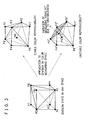
- FIG. 3 shows a state in which eight points P1 to P8 distributed in the basic color space are subdivided by five triangular pyramids; and when stable color reproducibility is attained, FIG. 3 shows that even if the subdivision information is applied to associated points in the color measuring space, the respective triangular pyramids are expressed not to overlap with each other as P1' to P8'.
- the number of color patches produced from the color image output device is required to be increased such that the measuring points are distributed more dense in the color measuring space.
- devices to implement automation of color patch measurement are easily available and hence it is expected that the number of color measurement is increased.
- the number of color patches is increased, it is likely that the first problem easily occurs, and hence there exists a second problem that the number of color patches to be measured is limited (an upper limit).
- CMKY four colors are basic colors
- the color gamut is reduced in the color measuring space if the black color device value is increased, and hence there exists a third problem that when the black color device value is increased, it is likely that the first problem easily occurs.
- the polyhedral subdivision in the basic color space becomes complex, and hence there exists a fifth problem that when at least five basic colors are used, the polyhedral subdivision in the basic color space is not practical.
- a first object of the present invention is to provide, to solve the first and third problems, a color conversion method, a color converting device, and a color conversion program robust for unstableness in the color reproduction of a color image device.
- a second object of the present invention is to provide, to solve the second problem, a color conversion method, a color converting device, and a color conversion program not requiring any restriction regarding the number of patches which are produced and measured in a color image device.
- a third object of the present invention is to provide, to solve the fourth problem, a color conversion method capable of freely setting the color device value constituting color patches which are produced and measured in a color image device. That is, the object is to provide a color conversion method, a color converting device, and a color conversion program in which when there are given color device values uniformly distributed in a color measuring space or color device values generated in a random fashion and measured color data associated therewith, a color device value corresponding to an arbitrary color is calculated.
- a fourth object of the present invention is to provide, to solve the fifth problem, a color conversion method, a color converting device, and a color conversion program which can be easily applied to a color image device conducting color reproduction in at least five basic colors as in the color reproduction in three and four basic colors.
- a reference numeral 1 is color data input means.
- a reference numeral 2 is a color data storage memory.
- a reference numeral 3 is Delaunay diagram constructing means.
- a reference numeral 4 is a Delaunay tetrahedron storage memory.
- a reference numeral 5 is Delaunay tetrahedron searching means.
- a reference numeral 6 is color device value calculating means.
- a reference numeral 7 is paste processing and color device value calculating means.
- a reference numeral 8 is Delaunay diagram constructing and shaping means.
- a reference numeral 9 is Delaunay tetrahedron searching and color device value calculating means.
- a reference numeral 20 is a color conversion program.
- a reference numeral 21 is a color conversion line unit (LUT).
- a reference numeral 22 is an image conversion program.
- a reference numeral 100 is a color converting device.
- a reference numeral 101 is a color converting device.
- a reference numeral 102 is a color converting device.
- a reference numeral 103 is a color converting device.
- a reference numeral 200 is a computer system.
- a plurality of color patches constructed by combinations of arbitrary device values are first outputted to or displayed on a color image device conducting color reproduction in N basic colors. Then, color measuring is conducted for all color patches to attain measured color data, for example, tristimulus values X, Y, Z and a uniform color space L*a*b*.
- measured color data for example, tristimulus values X, Y, Z and a uniform color space L*a*b*.
- a color device value and a measured color value are stored for each color patch.
- the color measuring of the color patches aims at obtaining a color gamut of the color image device, and precision of the color conversion depends on its sampling density. Therefore, to increase the color conversion precision, the number of color patches are increased to be uniformly distributed in the color gamut of the color image device.
- the color device values may be generated for use, for example, by using random numbers.
- the color gamut of the color image device expressed by measured color data distributed in the three-dimensional space is subdivided by using Delaunay tetrahedrons.
- the method of subdividing the color gamut using Delaunay tetrahedrons is implemented by constructing Delaunay tetrahedrons such that a sphere passing four measured color data not existing on one plane is obtained and a Delaunay tetrahedron is constructed using the four measured color data as its vertices while no measured color data exists within the sphere.
- a central point and a radius R1 of the sphere S1 are calculated and distance L between the central point and a data point is calculated to compare the radius R1 with the distance L. If the distance L is more than the radius R1, the data point exists outside the sphere S1.
- Voronoi diagram Delaunay diagram constructing algorithm according to a sequential generatrix addition method, highest priority is assigned to the retaining of topological characteristics to mathematically stabilize the Voronoi diagram. Necessary conditions of topological characteristics to be satisfied by a three-dimensional Voronoi diagram are as below.
- a Delaunay diagram is a dual diagram of a Voronoi diagram
- a Voronoi diagram is readily obtained.
- an event in which data points (generatrices) distributed in a color space obtained by measuring color patches enter a degenerate state occurs with a considerably low probability.
- the Voronoi diagram Delaunay diagram constructing method by using topological characteristics as a basis, there is obtained an advantage that the exception processing for the degeneration is not required.
- a field of sets of Delaunay tetrahedrons constructed by the two Delaunay diagram constructing algorithms form a convex hull. Therefore, depending on the contour of the color gamut of the color image device, it is required to delete unnecessary ones from the constructed Delaunay tetrahedrons.
- processing is executed for Delaunay tetrahedrons existing on the surface to delete Delaunay tetrahedrons exceeding a threshold value by using, for example,
- FIG. 5 shows an example of data structure to store the linkage information of measured color data distributed in a three-dimensional space subdivided using Delaunay tetrahedrons.
- an identifier number allocated to the Delaunay tetrahedron numbers of four measured color data constituting the Delaunay tetrahedron; and for each of four triangular planes constituting the Delaunay tetrahedron, numbers of three measured color data constituting the triangular plan, and adjacent information of the triangular plan.
- the identifier number of the Delaunay tetrahedron a sequential number is assigned to each Delaunay tetrahedron when the Delaunay diagram is constructed.
- an identifier number of the second Delaunay tetrahedron is described as the adjacent information.
- an identifier indicating the condition is set thereto.
- a Delaunay tetrahedron is adjacent to at least one other Delaunay tetrahedron.
- at least one of the four triangular planes constituting the Delaunay tetrahedron is not adjacent to any other Delaunay tetrahedron, it is indicated that the Delaunay tetrahedron is on the surface.
- FIG. 6 shows a state in which a color gamut in a three-dimensional space constituted by five measured color data P1 to P5 is subdivided using two Delaunay tetrahedrons.
- the Delaunay tetrahedron constructed by (P1,P2,P3,P4) is indicated by 1 and that constructed by (P2,P3,P4,P5) is indicated by 2.
- FIG. 7 shows an example of data structure to store linkage information of measured color data distributed in the three-dimensional color space.
- an identifier of a case in which there does not exist a Delaunay tetrahedron adjacent to a triangular plane is -1.
- a search is made for a Delaunay tetrahedron including the input color from the group of Delaunay tetrahedrons in the three-dimensional color space.
- a method of searching for the Delaunay tetrahedron the method described in Japanese Patent Laid-Open Publication Ser. No. 06-022124 can be used.
- one point A is selected from four vertices of a Delaunay tetrahedron.
- the input color is a color existing in the color gamut of the color image device, there exists at least one Delaunay tetrahedron including the input color.
- the input color is on a boundary plane or a boundary line of the Delaunay tetrahedrons, there exist two or more Delaunay tetrahedrons.
- Color device values corresponding to the input value can be calculated by interpolation using color device values in the color image device corresponding to four vertices of the retrieved Delaunay tetrahedron and relative positions of the input color in the Delaunay tetrahedron.
- the method described in Japanese Patent Laid-Open Publication Ser. No. 06-022124 can be used. In this connection, although the method described in Japanese Patent Laid-Open Publication Ser. No. 06-022124 is explained for three CMY colors, but the method can be easily expanded also for four or more basic colors.
- the input color is a color outside the color gamut of the color image device.
- a triangular plane is retrieved from a plurality of triangular planes forming the surface of the color gamut, the triangular plane intersecting a line segment linking a point within the color gamut with the input color. Thereafter, an intersection between the triangular plane and the line segment is assumed as a reproduced color of the input color on the color image device to calculate color device values corresponding to the reproduced color.
- a method of retrieving a triangular plane intersecting line segment AB linking the input color with point B(1,m,n), which is a point within the color gamut, is as follows. Assume that an intersection between line segment AB and a triangular plane configured by point P1 (x1,y1,z1), point P2 (x2,y2,z2), and point P3 (x3,y3,z3) is X.
- the device color values as N basic colors of the color image device corresponding to P1, P2, and P3 are respectively (C1,M1,Y1, ..., X1), (C2,M2,Y2, ..., X2), and (C3,M3,Y3, ..., X3)
- the device color values (C,M,Y,...,X) at the intersection X are as below.
- color area compression to adjust the color gamut on the input side to that on the output side is beforehand conducted for the color gamut on the input side depending on cases.
- data undergone the color area compression may be inputted.
- the color conversion method of the present invention may be used as a method to obtain optimal color area compression to adjust the color gamut on the input side to that on the output side.
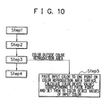
- the first color conversion method of the present invention includes, as shown in FIG. 9 , step 1 to read color device values of the color image device and a plurality of sets of measured data thereof, step 2 to subdivide the color gamut constructed by measured color data distributed in the three-dimensional color space using Delaunay tetrahedrons, step 3 to search for a Delaunay tetrahedron including the color of input colors given thereto, and step 4 to calculate device values corresponding to the input color using the relative position of the input color in the Delaunay tetrahedron and device values of the color image device corresponding to four vertices of the Delaunay tetrahedron.
- the second color conversion method of the present invention includes, in addition to the first color conversion method, step 5 which pastes, when it is impossible to retrieve a Delaunay tetrahedron including the given input color in step 3, the input color on one point on a triangular plane of one of the Delaunay tetrahedrons existing on the surface of the color gamut to calculate color device values corresponding to the input color using the relative position of the point on the triangular plane and color device values corresponding to three vertices of the triangular plane.
- the third color conversion method of the present invention is configured by replacing step 2 of the first and second color conversion methods by step 2' including, in addition to step 2, processing to subdivide the color gamut constructed by the measured color data distributed in the three-dimensional color space by Delaunay tetrahedrons to thereafter delete unnecessary ones of the Delaunay tetrahedrons.
- the fourth color conversion method of the present invention is configured by replacing the Delaunay tetrahedrons retrieval processing of step 3 and the color device value calculation processing of step 4 in the first to fourth color conversion methods by step 6 in which both processing is combined into one processing part
- the device 100 includes color data input means 1 for reading therein color device values and measured color data of a color image device given as inputs, a color data storage memory 2 for storing the color device values and the measured color data thus obtained, Delaunay diagram constructing means 3 for subdividing a color gamut of the color image device constituted by the measured color data distributed in a three-dimensional space using Delaunay tetrahedrons, a Delaunay tetrahedron storage memory 4 for storing subdivision information of the Delaunay tetrahedrons, Delaunay tetrahedron searching means 5 for searching for a Delaunay tetrahedron including the input color from the Delaunay tetrahedrons, and color device value calculating means 6 for calculating color device values corresponding to the input color using the relative position of the input color in the Delaunay t
- the color data input means 1 reads therein color device values and measured color data of the color image device given as inputs and stores a data number, the color device value, and the measured color in the color data storage memory 2, for example, as shown in FIG. 13 .
- the Delaunay diagram constructing means 3 subdivides a color gamut of the color image device constituted by the measured color data stored in the memory 2 and distributed in a three-dimensional space using Delaunay tetrahedrons having the measured data as vertices. The method of constructing the Delaunay diagram is as described for the color conversion method.
- the means 3 expresses the subdivision information of the Delaunay tetrahedrons, for example, in the data structure shown in FIG. 7 to record the information in the Delaunay tetrahedron storage memory 4.
- the Delaunay tetrahedron searching means 5 searches for a Delaunay tetrahedron including the input color from the Delaunay tetrahedrons stored in the memory 4. The method of searching for a Delaunay tetrahedron including the input color is as described in conjunction with the color conversion method.
- the color device value calculating means 6 calculates and outputs color device values of the color image device corresponding to the input color by interpolation calculation using the relative position of the input color in the Delaunay tetrahedron retrieved by the means 5 and color device values corresponding to four vertices of the Delaunay tetrahedron.
- the method of calculating the color device values corresponding to the input color is as described in conjunction with the color conversion method.
- FIG. 14 is a block diagram showing the color converting device 101.
- the device 101 is implemented by adding, to the configuration of the color converting device 100, paste processing and color device calculating means 7 which pastes, when a Delaunay tetrahedron including the input color cannot be retrieved, the input color to a point on a triangular plane of one of the Delaunay tetrahedrons existing on the surface of the color gamut and which calculates color device values corresponding to the input color using the relative position of the point on the triangular plane and color device values corresponding to three vertices of the triangular plane.
- the means and the memories other than the paste processing and color device calculating means 7 in the color converting device 101 function as processing operations or storage memories which are equal to those of the color converting device 100.
- the means 7 pastes, when the Delaunay tetrahedron searching means 5 cannot retrieve a Delaunay tetrahedron including the input color, the input color to a point on a triangular plane of one of the Delaunay tetrahedrons existing on the surface of the color gamut and then calculates color device values corresponding to the input color using the relative position of the point on the triangular plane and color device values corresponding to three vertices of the triangular plane.
- the paste processing method and the color device value calculating method are as described for the color conversion method of the present invention.
- FIG. 15 is a block diagram showing the color converting device 102.
- the device 102 is implemented by replacing the Delaunay diagram constructing means 3 of the color converting device 101 by Delaunay diagram constructing and shaping means 8.
- the means and the memories other than the Delaunay diagram constructing and shaping means 8 in the color converting device 102 function as processing operations or storage memories which are equal to those of the color converting device 101.
- the means 8 executes processing to construct a Delaunay diagram by subdividing the color gamut constituted by measured data distributed in the three-dimensional color space using Delaunay tetrahedrons and then to delete unnecessary Delaunay tetrahedrons.
- the Delaunay diagram constructing method and the method of deleting unnecessary Delaunay tetrahedrons are as described for the color conversion method of the present invention.
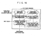
- FIG. 16 is a block diagram showing the color converting device 103.
- the device 103 is implemented by replacing the Delaunay tetrahedron searching means 5 and the color device value calculating means 6 of the color converting device 102 in FIG. 15 by Delaunay tetrahedron searching and color device calculating means 9.
- the means and the memories other than the Delaunay tetrahedron searching and color device calculating means 9 in the color converting device 103 function as processing operations or storage memories which are equal to those of the color converting device 102.
- the processing to search for a Delaunay tetrahedron including the input color and the processing to calculate color device values corresponding to the input color can be combined into one processing part. This is implemented as the Delaunay tetrahedron searching and color device calculating means 9.
- the Delaunay tetrahedron searching means 5 and the color device calculating means 6 in the color converting device 100 to 102 can also be replaced by the Delaunay tetrahedron searching and color device calculating means 9.
- FIG. 17 shows an example of a computer system on which a color conversion program is mounted.
- the computer system 200 of FIG. 17 includes a color conversion program 20, a color conversion LUT 21, and an image conversion program 22.
- the computer system 200 conducts a color conversion for an input image to generate an output image.
- the color conversion program 20 is a software program implementing one of the color converting devices 100 to 103. For a plurality of input colors set in advance, the program 20 calculates color device values of the color image device on the output side and describes the values in the color conversion LUT 21.
- the image conversion program 22 converts by the LUT 21 a color of each pixel read from an input image into a color device value of the color image device on the output side.
- a first advantage is that there can be provided a color conversion method, a color converting device, and a color conversion program robust for unstableness of color reproduction in a color image device.
- the reason is that the subdivision information of triangular pyramids in the device color space of the color converting device is not required to construct a Delaunay diagram using only measured color data distributed in a three-dimensional color space to subdivide the color gamut of the color image device using Delaunay tetrahedrons.
- a second advantage is that there can be provided a color conversion method, a color converting device, and a color conversion program not requiring the restriction regarding the number of color patches produced from and measured by the color image device.
- a third advantage is that there can be provided a color conversion method, a color converting device, and a color conversion program capable of freely setting color device values constituting the color patches produced from and measured by the color image device.
- a fourth advantage is that there can be provided a color conversion method, a color converting device, and a color conversion program which can be easily applied also to a color image device conducting color reproduction in at least five basic colors as in the color reproduction in three and four basic colors.
Landscapes
- Engineering & Computer Science (AREA)
- Multimedia (AREA)
- Signal Processing (AREA)
- Physics & Mathematics (AREA)
- General Physics & Mathematics (AREA)
- Theoretical Computer Science (AREA)
- Facsimile Image Signal Circuits (AREA)
- Image Processing (AREA)
- Color Image Communication Systems (AREA)
- Color, Gradation (AREA)
Claims (7)
- Procédé de conversion de couleurs pour convertir des couleurs d'entrée en valeurs de dispositif de couleurs d'un dispositif de reproduction d'images en couleurs, comprenant :une étape d'entrée de données de couleurs (étape 1) consistant à lire des valeurs de dispositif de couleurs du dispositif de reproduction d'images en couleurs et des données de couleurs mesurées de celui-ci dans le dispositif d'images en couleurs,une étape de construction de diagramme de Delaunay (étape 2) consistant à construire un diagramme de Delaunay représentant une gamme de couleurs du dispositif de reproduction d'images en couleurs en subdivisant la gamme de couleurs du dispositif de reproduction d'images en couleurs comprenant les données de couleurs mesurées réparties dans un espace de couleurs tridimensionnel en utilisant des tétraèdres de Delaunay et en supprimant les tétraèdres de Delaunay ayant une longueur d'un côté d'un plan triangulaire qui dépasse une valeur de seuil,une étape d'entrée consistant à entrer des couleurs d'entrée, dans lequel, pour chaque couleur d'entrée, le procédé comprend en outre :une étape de recherche de tétraèdre de Delaunay (étape 3) consistant à chercher un tétraèdre de Delaunay comprenant les couleurs d'entrée par le biais du diagramme de Delaunay, etune étape de calcul de valeurs de dispositif de couleurs (étape 4) consistant à calculer et délivrer des valeurs de dispositif de couleurs correspondant aux couleurs d'entrée en utilisant une position relative des couleurs d'entrée dans le tétraèdre de Delaunay et des valeurs de dispositif de couleurs correspondant à quatre sommets du tétraèdre de Delaunay.
- Procédé de conversion de couleurs selon la revendication 1, caractérisé en ce qu'il comprend en outre l'étape de recherche de tétraèdre de Delaunay (étape 3) consistant à chercher, lorsque le tétraèdre de Delaunay comprenant les couleurs d'entrée ainsi données ne peut pas être extrait, une intersection d'un segment de ligne reliant la couleur d'entrée à un point à l'intérieur de la gamme de couleurs du dispositif d'images en couleurs et d'un plan triangulaire de l'un des tétraèdres de Delaunay existant sur une surface de la gamme de couleurs, et l'étape de calcul de valeurs de dispositif de couleurs (étape 4) consistant à calculer des valeurs de dispositif de couleurs correspondant aux couleurs d'entrée en utilisant une position relative de l'intersection sur le plan triangulaire et des valeurs de dispositif de couleurs correspondant à trois sommets du plan triangulaire.
- Procédé de conversion de couleurs selon la revendication 1 ou 2, caractérisé en ce que le traitement exécuté à l'étape de recherche de tétraèdre de Delaunay (étape 3) et le traitement exécuté à l'étape de calcul de valeurs de dispositif de couleurs (étape 4) sont réalisés par une partie de traitement.
- Dispositif de conversion de couleurs (100) pour convertir des valeurs de dispositif de couleurs d'entrée d'un dispositif de reproduction d'images en couleurs, comprenant :des moyens d'entrée de données de couleurs (1) destinés à lire des valeurs de dispositif de couleurs du dispositif de reproduction d'images en couleurs et des données de couleurs mesurées de celui-ci dans le dispositif d'images en couleurs,une mémoire de stockage de données de couleurs (2) pour stocker un ensemble des valeurs de dispositif de reproduction de couleurs et les données de couleurs mesurées de celui-ci,des moyens de construction de diagramme de Delaunay (3) destiné à construire un diagramme de Delaunay représentant une gamme de couleurs du dispositif de reproduction d'images en couleurs en subdivisant la gamme de couleurs du dispositif de reproduction d'images en couleur comprenant les données de couleurs mesurées réparties dans un espace de couleurs tridimensionnel en utilisant des tétraèdres de Delaunay et en supprimant les tétraèdres de Delaunay ayant une longueur d'un côté d'un plan triangulaire qui dépasse une valeur de seuil,une mémoire de stockage de tétraèdre de Delaunay (4) pour stocker des informations du diagramme de Delaunay,un moyen d'entrée destiné à entrer des couleurs d'entrée, dans lequel, pour chaque couleur d'entrée, le dispositif de reproduction de couleurs d'entrée comprend en outre :des moyens de recherche de tétraèdre de Delaunay (5) destiné à chercher, pour des couleurs d'entrée, un tétraèdre de Delaunay comprenant la couleur d'entrée par le biais du diagramme de Delaunay, etdes moyens de calcul de valeur de dispositif de couleurs (6) destiné à calculer et délivrer des valeurs de dispositif de couleurs correspondant à la couleur d'entrée en utilisant une position relative des couleurs d'entrée dans le tétraèdre de Delaunay comprenant les couleurs d'entrée et des valeurs de dispositif de couleurs correspondant à quatre sommets du tétraèdre de Delaunay.
- Dispositif de conversion de couleurs (100) selon la revendication 4, caractérisé en ce qu'il comprend les moyens de recherche de tétraèdre de Delaunay (5) pour chercher, lorsque le tétraèdre de Delaunay comprenant les couleurs d'entrée ainsi données ne peut pas être extrait, une intersection d'un segment de ligne reliant la couleur d'entrée à un point à l'intérieur de la gamme de couleurs du dispositif d'images en couleurs et d'un plan triangulaire de l'un des tétraèdres de Delaunay existant sur une surface de la gamme de couleurs, et les moyens de calcul de valeur de dispositif de couleurs (6) pour calculer des valeurs de dispositif de couleurs correspondant aux couleurs d'entrée en utilisant une position relative de l'intersection sur le plan triangulaire et des valeurs de dispositif de couleurs correspondant à trois sommets du plan triangulaire.
- Dispositif de conversion de couleurs (100) selon la revendication 4 ou 5, caractérisé en ce que les moyens de recherche de tétraèdre de Delaunay (5) et les moyens de calcul de valeur de dispositif de couleurs (6) sont remplacés par des moyens de recherche de tétraèdre de Delaunay et de calcul de valeur de dispositif de couleurs (9) mettant en oeuvre l'opération de recherche de tétraèdre de Delaunay et l'opération de calcul de valeur de dispositif de couleurs par une partie de traitement.
- Programme informatique pour effectuer un procédé selon l'une quelconque des revendications 1 à 3.
Applications Claiming Priority (3)
| Application Number | Priority Date | Filing Date | Title |
|---|---|---|---|
| JP2002149745A JP4787453B2 (ja) | 2002-05-23 | 2002-05-23 | 色変換方法、色変換装置および色変換プログラム |
| JP2002149745 | 2002-05-23 | ||
| PCT/JP2003/006391 WO2003101084A1 (fr) | 2002-05-23 | 2003-05-22 | Procede, dispositif et programme de conversion de couleur |
Publications (3)
| Publication Number | Publication Date |
|---|---|
| EP1507403A1 EP1507403A1 (fr) | 2005-02-16 |
| EP1507403A4 EP1507403A4 (fr) | 2008-03-19 |
| EP1507403B1 true EP1507403B1 (fr) | 2012-09-26 |
Family
ID=29561218
Family Applications (1)
| Application Number | Title | Priority Date | Filing Date |
|---|---|---|---|
| EP03730577A Expired - Lifetime EP1507403B1 (fr) | 2002-05-23 | 2003-05-22 | Procede, dispositif et programme de conversion de couleur |
Country Status (6)
| Country | Link |
|---|---|
| US (1) | US7557952B2 (fr) |
| EP (1) | EP1507403B1 (fr) |
| JP (1) | JP4787453B2 (fr) |
| KR (1) | KR100749993B1 (fr) |
| CN (1) | CN100379252C (fr) |
| WO (1) | WO2003101084A1 (fr) |
Families Citing this family (14)
| Publication number | Priority date | Publication date | Assignee | Title |
|---|---|---|---|---|
| JP4393294B2 (ja) * | 2004-07-07 | 2010-01-06 | キヤノン株式会社 | 画像処理装置およびその方法 |
| JP4481840B2 (ja) * | 2005-01-20 | 2010-06-16 | キヤノン株式会社 | 情報処理方法および装置 |
| US7626742B2 (en) * | 2005-02-16 | 2009-12-01 | Samsung Electronics Co., Ltd. | Color data conversion apparatus and method using gamut boundary descriptors |
| JP4453833B2 (ja) * | 2005-05-20 | 2010-04-21 | 富士ゼロックス株式会社 | 色処理装置、色処理方法、色処理プログラム、および、記憶媒体 |
| CN100450144C (zh) * | 2005-06-17 | 2009-01-07 | 诚研科技股份有限公司 | 可转换不同色域的像素的色彩管理方法 |
| US7330193B2 (en) * | 2005-07-08 | 2008-02-12 | Seiko Epson Corporation | Low noise dithering and color palette designs |
| JP4595734B2 (ja) * | 2005-08-03 | 2010-12-08 | セイコーエプソン株式会社 | プロファイル作成方法、プロファイル作成装置、プロファイル作成プログラム、印刷制御方法、印刷制御装置、及び印刷制御プログラム |
| US9951438B2 (en) | 2006-03-07 | 2018-04-24 | Samsung Electronics Co., Ltd. | Compositions, optical component, system including an optical component, devices, and other products |
| EP2023602A1 (fr) * | 2007-07-27 | 2009-02-11 | THOMSON Licensing | Procédé de description d'une gamme de couleur actuelle d'un dispositif de couleur ou d'un contenu de couleur |
| JP2011081030A (ja) * | 2009-10-02 | 2011-04-21 | Tani Electronics Corp | 検索型カラー暗号化ファイルの構成方法および検索型カラー暗号化ファイルシステム |
| US9929325B2 (en) | 2012-06-05 | 2018-03-27 | Samsung Electronics Co., Ltd. | Lighting device including quantum dots |
| JP6237291B2 (ja) * | 2014-02-06 | 2017-11-29 | 富士通株式会社 | 情報処理装置、色補間方法、プログラム、及びテーブル生成方法 |
| CN105825829B (zh) * | 2016-05-18 | 2018-07-17 | 深圳市华星光电技术有限公司 | 石墨烯显示器以及石墨烯显示器的驱动方法、驱动装置 |
| US11595549B2 (en) * | 2020-04-22 | 2023-02-28 | The Boeing Company | Aircraft inkjet printing |
Family Cites Families (14)
| Publication number | Priority date | Publication date | Assignee | Title |
|---|---|---|---|---|
| JP2895086B2 (ja) | 1989-02-28 | 1999-05-24 | コニカ株式会社 | 色推定方法 |
| JP3153002B2 (ja) * | 1992-06-30 | 2001-04-03 | 日本電気株式会社 | 色変換方法、色変換テーブル作成方法、色変換装置および色変換テーブル作成装置 |
| JP2621789B2 (ja) | 1994-04-19 | 1997-06-18 | 日本電気株式会社 | 色変換方法、色変換装置および色変換テーブル作成装置 |
| JPH08116460A (ja) | 1994-10-19 | 1996-05-07 | Fuji Xerox Co Ltd | カラーマスキングパラメータ決定装置 |
| US6173075B1 (en) * | 1995-08-30 | 2001-01-09 | Usanimation, Inc. | Drawing pixmap to vector conversion |
| JP3771315B2 (ja) * | 1996-04-15 | 2006-04-26 | 大日本印刷株式会社 | 画像処理装置 |
| US6268867B1 (en) | 1996-10-29 | 2001-07-31 | Mitsubishi Denki Kabushiki Kaisha | Method and apparatus for color correction and apparatus for applying color correction |
| JP3934206B2 (ja) * | 1997-06-10 | 2007-06-20 | 大日本印刷株式会社 | 画像処理装置 |
| US6480301B1 (en) * | 1999-11-15 | 2002-11-12 | Lexmark International, Inc. | Method and apparatus for gamut boundary determination |
| JP2002064721A (ja) | 2000-08-21 | 2002-02-28 | Seiko Epson Corp | プロファイル作成プログラムを記録した媒体、プロファイル作成装置、プロファイル作成方法およびプロファイルデータを記録した媒体 |
| US20020027603A1 (en) * | 2000-09-01 | 2002-03-07 | Seiko Epson Corporation | Apparatus, method, signal and computer program product configured to provide output image adjustment for image files |
| JP3720691B2 (ja) | 2000-09-12 | 2005-11-30 | キヤノン株式会社 | 色処理方法および装置 |
| JP2002094812A (ja) * | 2000-09-12 | 2002-03-29 | Canon Inc | 画像処理方法、装置および記録媒体 |
| JP4035283B2 (ja) * | 2000-10-04 | 2008-01-16 | キヤノン株式会社 | 画像処理システム及びその制御方法 |
-
2002
- 2002-05-23 JP JP2002149745A patent/JP4787453B2/ja not_active Expired - Lifetime
-
2003
- 2003-05-22 EP EP03730577A patent/EP1507403B1/fr not_active Expired - Lifetime
- 2003-05-22 WO PCT/JP2003/006391 patent/WO2003101084A1/fr not_active Ceased
- 2003-05-22 KR KR1020047018853A patent/KR100749993B1/ko not_active Expired - Fee Related
- 2003-05-22 US US10/515,216 patent/US7557952B2/en not_active Expired - Lifetime
- 2003-05-22 CN CNB038118378A patent/CN100379252C/zh not_active Expired - Fee Related
Also Published As
| Publication number | Publication date |
|---|---|
| US7557952B2 (en) | 2009-07-07 |
| KR100749993B1 (ko) | 2007-08-16 |
| CN1656790A (zh) | 2005-08-17 |
| CN100379252C (zh) | 2008-04-02 |
| US20050179915A1 (en) | 2005-08-18 |
| EP1507403A1 (fr) | 2005-02-16 |
| EP1507403A4 (fr) | 2008-03-19 |
| WO2003101084A1 (fr) | 2003-12-04 |
| JP2003348362A (ja) | 2003-12-05 |
| JP4787453B2 (ja) | 2011-10-05 |
| KR20050004190A (ko) | 2005-01-12 |
Similar Documents
| Publication | Publication Date | Title |
|---|---|---|
| JP4595734B2 (ja) | プロファイル作成方法、プロファイル作成装置、プロファイル作成プログラム、印刷制御方法、印刷制御装置、及び印刷制御プログラム | |
| US6870636B2 (en) | Determining color mappings for a color printer | |
| EP1507403B1 (fr) | Procede, dispositif et programme de conversion de couleur | |
| US7034842B1 (en) | Color characteristic description apparatus, color management apparatus, image conversion apparatus and color correction method | |
| US5581376A (en) | System for correcting color images using tetrahedral interpolation over a hexagonal lattice | |
| EP0681396A2 (fr) | Méthode et dispositif pour le calibrage d'une imprimante à quatre couleurs | |
| US7542167B2 (en) | Smoothing lattice positions | |
| JPH08237495A (ja) | 選択されたカラーを正確に描写するためのカラープリンタ校正方法 | |
| US7450267B2 (en) | Accuracy of color conversion profile | |
| JPH08125880A (ja) | ローカルプリンタの非線形性を補正する、カラープリンタのキャリブレーション方法 | |
| US7215440B2 (en) | Fast interpolation of large color lookup tables | |
| JP4276561B2 (ja) | 色変換定義作成方法、プロファイル作成方法、色変換定義作成装置、プロファイル作成装置、色変換定義作成プログラム、およびプロファイル作成プログラム | |
| JP2000188697A (ja) | 画像処理方法およびその装置、並びに、そのプロセスステップ | |
| JPH10276337A (ja) | カラー画像処理装置 | |
| USRE37940E1 (en) | Interpolation method and color correction method using interpolation | |
| US7196823B2 (en) | Method of creating lookup table for color conversion | |
| US20100302596A1 (en) | Color look up table adjusting apparatus, recording medium on which a color look up table adjusting program is recorded and color look up table adjusting system | |
| JP3362281B2 (ja) | 色再現装置及び色再現方法 | |
| JP3611890B2 (ja) | 色変換装置 | |
| JP2009071715A (ja) | 色域作成方法、色域作成装置、プログラム及び記憶媒体 | |
| JP2005167503A (ja) | 画像処理装置およびそれを備えた画像形成装置 | |
| JPH0690353A (ja) | 色分解画像修正方法 | |
| JPH0951421A (ja) | 画像処理装置及び方法 | |
| KR20040017430A (ko) | 프린터용 색 표본 생성방법 | |
| WO2021150242A1 (fr) | Mise à jour d'un profil de couleur |
Legal Events
| Date | Code | Title | Description |
|---|---|---|---|
| PUAI | Public reference made under article 153(3) epc to a published international application that has entered the european phase |
Free format text: ORIGINAL CODE: 0009012 |
|
| 17P | Request for examination filed |
Effective date: 20041122 |
|
| AK | Designated contracting states |
Kind code of ref document: A1 Designated state(s): AT BE BG CH CY CZ DE DK EE ES FI FR GB GR HU IE IT LI LU MC NL PT RO SE SI SK TR |
|
| RBV | Designated contracting states (corrected) |
Designated state(s): DE |
|
| A4 | Supplementary search report drawn up and despatched |
Effective date: 20080215 |
|
| 17Q | First examination report despatched |
Effective date: 20081021 |
|
| GRAP | Despatch of communication of intention to grant a patent |
Free format text: ORIGINAL CODE: EPIDOSNIGR1 |
|
| GRAS | Grant fee paid |
Free format text: ORIGINAL CODE: EPIDOSNIGR3 |
|
| GRAA | (expected) grant |
Free format text: ORIGINAL CODE: 0009210 |
|
| AK | Designated contracting states |
Kind code of ref document: B1 Designated state(s): DE |
|
| REG | Reference to a national code |
Ref country code: DE Ref legal event code: R096 Ref document number: 60342185 Country of ref document: DE Effective date: 20121122 |
|
| PLBE | No opposition filed within time limit |
Free format text: ORIGINAL CODE: 0009261 |
|
| STAA | Information on the status of an ep patent application or granted ep patent |
Free format text: STATUS: NO OPPOSITION FILED WITHIN TIME LIMIT |
|
| 26N | No opposition filed |
Effective date: 20130627 |
|
| REG | Reference to a national code |
Ref country code: DE Ref legal event code: R097 Ref document number: 60342185 Country of ref document: DE Effective date: 20130627 |
|
| PGFP | Annual fee paid to national office [announced via postgrant information from national office to epo] |
Ref country code: DE Payment date: 20160518 Year of fee payment: 14 |
|
| REG | Reference to a national code |
Ref country code: DE Ref legal event code: R119 Ref document number: 60342185 Country of ref document: DE |
|
| PG25 | Lapsed in a contracting state [announced via postgrant information from national office to epo] |
Ref country code: DE Free format text: LAPSE BECAUSE OF NON-PAYMENT OF DUE FEES Effective date: 20171201 |