EP1508416B1 - Verfahren zur herstellung eines wabensturkturkörpers - Google Patents
Verfahren zur herstellung eines wabensturkturkörpers Download PDFInfo
- Publication number
- EP1508416B1 EP1508416B1 EP03730511A EP03730511A EP1508416B1 EP 1508416 B1 EP1508416 B1 EP 1508416B1 EP 03730511 A EP03730511 A EP 03730511A EP 03730511 A EP03730511 A EP 03730511A EP 1508416 B1 EP1508416 B1 EP 1508416B1
- Authority
- EP
- European Patent Office
- Prior art keywords
- honeycomb structure
- slurry
- plugged
- cells
- drying
- Prior art date
- Legal status (The legal status is an assumption and is not a legal conclusion. Google has not performed a legal analysis and makes no representation as to the accuracy of the status listed.)
- Expired - Lifetime
Links
- 238000004519 manufacturing process Methods 0.000 title abstract description 6
- 239000002002 slurry Substances 0.000 claims abstract description 52
- 238000001035 drying Methods 0.000 claims abstract description 40
- 239000000919 ceramic Substances 0.000 claims abstract description 30
- 239000000843 powder Substances 0.000 claims abstract description 13
- 238000000034 method Methods 0.000 claims description 39
- 239000011230 binding agent Substances 0.000 claims description 16
- 238000005485 electric heating Methods 0.000 claims description 15
- 239000002612 dispersion medium Substances 0.000 claims description 8
- 239000012530 fluid Substances 0.000 claims description 4
- 238000007598 dipping method Methods 0.000 claims description 3
- 210000004027 cell Anatomy 0.000 description 36
- 239000002313 adhesive film Substances 0.000 description 21
- 229920000609 methyl cellulose Polymers 0.000 description 13
- 239000001923 methylcellulose Substances 0.000 description 13
- 235000010981 methylcellulose Nutrition 0.000 description 13
- XLYOFNOQVPJJNP-UHFFFAOYSA-N water Substances O XLYOFNOQVPJJNP-UHFFFAOYSA-N 0.000 description 12
- 230000000873 masking effect Effects 0.000 description 9
- 229910052878 cordierite Inorganic materials 0.000 description 7
- JSKIRARMQDRGJZ-UHFFFAOYSA-N dimagnesium dioxido-bis[(1-oxido-3-oxo-2,4,6,8,9-pentaoxa-1,3-disila-5,7-dialuminabicyclo[3.3.1]nonan-7-yl)oxy]silane Chemical compound [Mg++].[Mg++].[O-][Si]([O-])(O[Al]1O[Al]2O[Si](=O)O[Si]([O-])(O1)O2)O[Al]1O[Al]2O[Si](=O)O[Si]([O-])(O1)O2 JSKIRARMQDRGJZ-UHFFFAOYSA-N 0.000 description 7
- 238000005192 partition Methods 0.000 description 7
- 238000002156 mixing Methods 0.000 description 6
- 239000002245 particle Substances 0.000 description 6
- 230000000052 comparative effect Effects 0.000 description 5
- 239000000463 material Substances 0.000 description 5
- 239000004372 Polyvinyl alcohol Substances 0.000 description 4
- 238000001125 extrusion Methods 0.000 description 4
- 229920002451 polyvinyl alcohol Polymers 0.000 description 4
- 210000002421 cell wall Anatomy 0.000 description 3
- 238000001704 evaporation Methods 0.000 description 3
- 230000008020 evaporation Effects 0.000 description 3
- 239000000853 adhesive Substances 0.000 description 2
- 230000001070 adhesive effect Effects 0.000 description 2
- 150000001732 carboxylic acid derivatives Chemical class 0.000 description 2
- 239000011248 coating agent Substances 0.000 description 2
- 238000000576 coating method Methods 0.000 description 2
- 239000000428 dust Substances 0.000 description 2
- 230000000694 effects Effects 0.000 description 2
- 238000011156 evaluation Methods 0.000 description 2
- 238000001914 filtration Methods 0.000 description 2
- 239000000047 product Substances 0.000 description 2
- 239000004094 surface-active agent Substances 0.000 description 2
- HMUNWXXNJPVALC-UHFFFAOYSA-N 1-[4-[2-(2,3-dihydro-1H-inden-2-ylamino)pyrimidin-5-yl]piperazin-1-yl]-2-(2,4,6,7-tetrahydrotriazolo[4,5-c]pyridin-5-yl)ethanone Chemical compound C1C(CC2=CC=CC=C12)NC1=NC=C(C=N1)N1CCN(CC1)C(CN1CC2=C(CC1)NN=N2)=O HMUNWXXNJPVALC-UHFFFAOYSA-N 0.000 description 1
- 208000010228 Erectile Dysfunction Diseases 0.000 description 1
- 239000004698 Polyethylene Substances 0.000 description 1
- 229910000831 Steel Inorganic materials 0.000 description 1
- 239000000654 additive Substances 0.000 description 1
- 230000015572 biosynthetic process Effects 0.000 description 1
- RKTYLMNFRDHKIL-UHFFFAOYSA-N copper;5,10,15,20-tetraphenylporphyrin-22,24-diide Chemical compound [Cu+2].C1=CC(C(=C2C=CC([N-]2)=C(C=2C=CC=CC=2)C=2C=CC(N=2)=C(C=2C=CC=CC=2)C2=CC=C3[N-]2)C=2C=CC=CC=2)=NC1=C3C1=CC=CC=C1 RKTYLMNFRDHKIL-UHFFFAOYSA-N 0.000 description 1
- 230000007797 corrosion Effects 0.000 description 1
- 238000005260 corrosion Methods 0.000 description 1
- 230000003247 decreasing effect Effects 0.000 description 1
- 230000007547 defect Effects 0.000 description 1
- 230000007613 environmental effect Effects 0.000 description 1
- 239000012467 final product Substances 0.000 description 1
- 238000007602 hot air drying Methods 0.000 description 1
- 239000002440 industrial waste Substances 0.000 description 1
- 239000002609 medium Substances 0.000 description 1
- -1 polyethylene Polymers 0.000 description 1
- 229920000573 polyethylene Polymers 0.000 description 1
- 238000011027 product recovery Methods 0.000 description 1
- 239000011347 resin Substances 0.000 description 1
- 229920005989 resin Polymers 0.000 description 1
- 239000007787 solid Substances 0.000 description 1
- 239000010959 steel Substances 0.000 description 1
Images


Classifications
-
- C—CHEMISTRY; METALLURGY
- C04—CEMENTS; CONCRETE; ARTIFICIAL STONE; CERAMICS; REFRACTORIES
- C04B—LIME, MAGNESIA; SLAG; CEMENTS; COMPOSITIONS THEREOF, e.g. MORTARS, CONCRETE OR LIKE BUILDING MATERIALS; ARTIFICIAL STONE; CERAMICS; REFRACTORIES; TREATMENT OF NATURAL STONE
- C04B35/00—Shaped ceramic products characterised by their composition; Ceramics compositions; Processing powders of inorganic compounds preparatory to the manufacturing of ceramic products
- C04B35/622—Forming processes; Processing powders of inorganic compounds preparatory to the manufacturing of ceramic products
- C04B35/626—Preparing or treating the powders individually or as batches ; preparing or treating macroscopic reinforcing agents for ceramic products, e.g. fibres; mechanical aspects section B
- C04B35/62605—Treating the starting powders individually or as mixtures
- C04B35/62625—Wet mixtures
-
- B—PERFORMING OPERATIONS; TRANSPORTING
- B01—PHYSICAL OR CHEMICAL PROCESSES OR APPARATUS IN GENERAL
- B01D—SEPARATION
- B01D41/00—Regeneration of the filtering material or filter elements outside the filter for liquid or gaseous fluids
- B01D41/02—Regeneration of the filtering material or filter elements outside the filter for liquid or gaseous fluids of loose filtering material
-
- B—PERFORMING OPERATIONS; TRANSPORTING
- B28—WORKING CEMENT, CLAY, OR STONE
- B28B—SHAPING CLAY OR OTHER CERAMIC COMPOSITIONS; SHAPING SLAG; SHAPING MIXTURES CONTAINING CEMENTITIOUS MATERIAL, e.g. PLASTER
- B28B11/00—Apparatus or processes for treating or working the shaped or preshaped articles
- B28B11/003—Apparatus or processes for treating or working the shaped or preshaped articles the shaping of preshaped articles, e.g. by bending
- B28B11/006—Making hollow articles or partly closed articles
-
- B—PERFORMING OPERATIONS; TRANSPORTING
- B28—WORKING CEMENT, CLAY, OR STONE
- B28B—SHAPING CLAY OR OTHER CERAMIC COMPOSITIONS; SHAPING SLAG; SHAPING MIXTURES CONTAINING CEMENTITIOUS MATERIAL, e.g. PLASTER
- B28B11/00—Apparatus or processes for treating or working the shaped or preshaped articles
- B28B11/003—Apparatus or processes for treating or working the shaped or preshaped articles the shaping of preshaped articles, e.g. by bending
- B28B11/006—Making hollow articles or partly closed articles
- B28B11/007—Using a mask for plugging
-
- C—CHEMISTRY; METALLURGY
- C04—CEMENTS; CONCRETE; ARTIFICIAL STONE; CERAMICS; REFRACTORIES
- C04B—LIME, MAGNESIA; SLAG; CEMENTS; COMPOSITIONS THEREOF, e.g. MORTARS, CONCRETE OR LIKE BUILDING MATERIALS; ARTIFICIAL STONE; CERAMICS; REFRACTORIES; TREATMENT OF NATURAL STONE
- C04B35/00—Shaped ceramic products characterised by their composition; Ceramics compositions; Processing powders of inorganic compounds preparatory to the manufacturing of ceramic products
- C04B35/622—Forming processes; Processing powders of inorganic compounds preparatory to the manufacturing of ceramic products
- C04B35/626—Preparing or treating the powders individually or as batches ; preparing or treating macroscopic reinforcing agents for ceramic products, e.g. fibres; mechanical aspects section B
- C04B35/62605—Treating the starting powders individually or as mixtures
- C04B35/62645—Thermal treatment of powders or mixtures thereof other than sintering
- C04B35/62655—Drying, e.g. freeze-drying, spray-drying, microwave or supercritical drying
-
- C—CHEMISTRY; METALLURGY
- C04—CEMENTS; CONCRETE; ARTIFICIAL STONE; CERAMICS; REFRACTORIES
- C04B—LIME, MAGNESIA; SLAG; CEMENTS; COMPOSITIONS THEREOF, e.g. MORTARS, CONCRETE OR LIKE BUILDING MATERIALS; ARTIFICIAL STONE; CERAMICS; REFRACTORIES; TREATMENT OF NATURAL STONE
- C04B35/00—Shaped ceramic products characterised by their composition; Ceramics compositions; Processing powders of inorganic compounds preparatory to the manufacturing of ceramic products
- C04B35/622—Forming processes; Processing powders of inorganic compounds preparatory to the manufacturing of ceramic products
- C04B35/626—Preparing or treating the powders individually or as batches ; preparing or treating macroscopic reinforcing agents for ceramic products, e.g. fibres; mechanical aspects section B
- C04B35/63—Preparing or treating the powders individually or as batches ; preparing or treating macroscopic reinforcing agents for ceramic products, e.g. fibres; mechanical aspects section B using additives specially adapted for forming the products, e.g.. binder binders
- C04B35/632—Organic additives
- C04B35/636—Polysaccharides or derivatives thereof
- C04B35/6365—Cellulose or derivatives thereof
-
- B—PERFORMING OPERATIONS; TRANSPORTING
- B28—WORKING CEMENT, CLAY, OR STONE
- B28B—SHAPING CLAY OR OTHER CERAMIC COMPOSITIONS; SHAPING SLAG; SHAPING MIXTURES CONTAINING CEMENTITIOUS MATERIAL, e.g. PLASTER
- B28B11/00—Apparatus or processes for treating or working the shaped or preshaped articles
- B28B11/24—Apparatus or processes for treating or working the shaped or preshaped articles for curing, setting or hardening
- B28B11/243—Setting, e.g. drying, dehydrating or firing ceramic articles
-
- C—CHEMISTRY; METALLURGY
- C04—CEMENTS; CONCRETE; ARTIFICIAL STONE; CERAMICS; REFRACTORIES
- C04B—LIME, MAGNESIA; SLAG; CEMENTS; COMPOSITIONS THEREOF, e.g. MORTARS, CONCRETE OR LIKE BUILDING MATERIALS; ARTIFICIAL STONE; CERAMICS; REFRACTORIES; TREATMENT OF NATURAL STONE
- C04B2235/00—Aspects relating to ceramic starting mixtures or sintered ceramic products
- C04B2235/02—Composition of constituents of the starting material or of secondary phases of the final product
- C04B2235/30—Constituents and secondary phases not being of a fibrous nature
- C04B2235/32—Metal oxides, mixed metal oxides, or oxide-forming salts thereof, e.g. carbonates, nitrates, (oxy)hydroxides, chlorides
- C04B2235/3205—Alkaline earth oxides or oxide forming salts thereof, e.g. beryllium oxide
- C04B2235/3206—Magnesium oxides or oxide-forming salts thereof
-
- C—CHEMISTRY; METALLURGY
- C04—CEMENTS; CONCRETE; ARTIFICIAL STONE; CERAMICS; REFRACTORIES
- C04B—LIME, MAGNESIA; SLAG; CEMENTS; COMPOSITIONS THEREOF, e.g. MORTARS, CONCRETE OR LIKE BUILDING MATERIALS; ARTIFICIAL STONE; CERAMICS; REFRACTORIES; TREATMENT OF NATURAL STONE
- C04B2235/00—Aspects relating to ceramic starting mixtures or sintered ceramic products
- C04B2235/02—Composition of constituents of the starting material or of secondary phases of the final product
- C04B2235/30—Constituents and secondary phases not being of a fibrous nature
- C04B2235/34—Non-metal oxides, non-metal mixed oxides, or salts thereof that form the non-metal oxides upon heating, e.g. carbonates, nitrates, (oxy)hydroxides, chlorides
- C04B2235/3427—Silicates other than clay, e.g. water glass
- C04B2235/3463—Alumino-silicates other than clay, e.g. mullite
- C04B2235/3481—Alkaline earth metal alumino-silicates other than clay, e.g. cordierite, beryl, micas such as margarite, plagioclase feldspars such as anorthite, zeolites such as chabazite
Definitions
- the present invention relates to a process for producing a honeycomb structure wherein some of a large number of the cells are plugged, which is suitably used, for example, as a dust-collecting filter.
- ceramic honeycomb structures superior in heat resistance and corrosion resistance have been used as a dust-collecting filter for environmental management (e.g. pollution control), product recovery from high-temperature gas, etc. in various sectors including chemistry, electric power, steel and industrial waste treatment.
- Ceramic honeycomb structures (hereinafter referred to simply as “honeycomb structures” in some cases) are suitably used, for example, as a dust-collecting filter for use in a high-temperature, corrosive gas atmosphere such as a diesel particulate filter (DPF) for trapping particulates emitted from a diesel engine.
- DPF diesel particulate filter
- honeycomb structures are in use in which some of a large number of the cells are plugged.
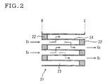
- a honeycomb structure 21 such as shown in Fig. 2 , wherein a large number of the cells 23 are alternately plugged at the inlet end face B and the outlet end face C by a plugged portion 22, a to-be-treated gas G 1 is allowed to enter unplugged cells 23 from the inlet end face B.
- the dust and particulates in the gas are captured by partition walls 24; meanwhile, the gas which has entered adjacent cells 23 through the porous partition walls 24, is discharged as a treated gas G 2 from the outlet end face C.
- Such a honeycomb structure can be produced by masking some of cells, at an end face of a tubular ceramic honeycomb structure having a plurality of cells each functioning as a fluid passage, dipping the masked end face of the ceramic honeycomb structure in slurry containing a ceramic powder, a dispersion medium, etc., to force the slurry into the cells without masking to form plugged portions therein, and drying the plugged portions.
- This drying of the plugged portions have heretofore been conducted, for example, by hot-air drying using a hot-air oven, see e.g. JP-A-2001-130970 .
- Fig. 3 is schematic enlarged sectional drawings of the vicinity of the inlet end face B of a honeycomb structure 21.
- Fig. 3(i) shows a plugged portion 22 to be formed satisfactorily.
- a shrunk dent 26 has generated as shown in Fig. 3(ii) and, in an extreme case, there has appeared a hole 27 passing through the plugged portion 22 as shown in Fig. 3(iii) .
- the present invention has been made in view of the above-mentioned problems of the prior art and aims at providing a process for producing a honeycomb structure capable of effectively preventing a problem of generation of shrunk dents or holes passing through the plugged portions.
- the present inventor made an intensive study in order to achieve the above aim. As a result, it was found that the above aim can be achieved by drying the plugged portions by a thermal conduction device and not by a conventional thermal convection device such as hot-air oven or the like.
- the present invention has been completed based on this finding. That is, the present invention provides the following process for producing a honeycomb structure.
- the present inventor In developing the present invention process for producing a honeycomb structure, the present inventor first investigated the reason why shrunk dents in plugged portions or holes passing through plugged portions are generated. As a result, it was found that when the plugged portions are dried by a conventional thermal convection device such as hot-air oven or the like, shrunk dents in the plugged portions or holes passing through the plugged portions generate, owing to the low drying speed of the thermal convection device.
- drying evaporation of the water in the slurry constituting plugged portions
- drying takes place slowly starting from the outer side of each plugged portion, i.e. the end face side of honeycomb structure owing to the relatively low drying speed of the thermal convection device.
- This is accompanied by slow movement of the water in the slurry from inner side of each plugged portion to the outer side, i.e. the end face side of honeycomb structure.
- drying of plugged portions was conducted by a thermal conduction device and not by a conventional thermal convection device such as hot-air oven or the like.
- a higher drying speed is obtained and drying (evaporation of the water in the slurry constituting each plugged portion) takes place instantly in the whole plugged portion; as a result, there does not take place the phenomenon that the water in the slurry moves slowly in each plugged portion from its inner side to the outer side, i.e. the end face side of honeycomb structure. Therefore, there does not take place the phenomenon that those ceramic particles not contacting with each cell inner wall move slowly, together with the water in the slurry, from inner side of each plugged portion to the outer side, i.e. the end face side of honeycomb structure. Consequently, the generation of shrunk dents in plugged portions or holes passing through plugged portions can be prevented effectively.
- the ceramic honeycomb structure produced by the present process is a ceramic honeycomb structure having a plurality of cells each functioning as a passage of a fluid.
- the material thereof is a ceramic.
- the process for producing the ceramic honeycomb structure There can be suitably used, for example, a process which comprises subjecting puddle of appropriately controlled viscosity to extrusion molding using an extrusion die having a desired cell shape, partition wall thickness and cell density, and drying the resulting extrudate.
- this ceramic honeycomb structure is sometimes referred to simply as "honeycomb structure"
- this ceramic honeycomb structure is sometimes referred to simply as "honeycomb structure”
- the process for masking there is no particular restriction as to the process for masking.
- a method of attaching an adhesive film to the whole area of an end face of the honeycomb structure and making holes partially in the adhesive film there can be suitably used, for example, a method of attaching an adhesive film to the whole area of an end face of the honeycomb structure and then making holes, by a laser, only in those areas of the film corresponding to the cells in which plugged portions need be formed.
- the thickness of the mask used is preferably 0.03 to 0.5 mm.
- the thickness of the mask is too large, the distance between each plugged portion to be formed and the thermal conduction device (e.g. electric heating plate) used is large and a gap may be present between them; therefore, the speed of thermal conduction is small and shrunk dents generate easily.
- the thickness of the mask is too small, the strength of the mask is low; as a result, the operation of attaching the mask to the end face of the honeycomb structure is difficult, resulting in reduced workability.
- the adhesive film there can be suitably used, for example, one obtained by coating an adhesive to one side of a polyethylene-made film.
- a commercial adhesive film having the above-mentioned thickness range can be selected appropriately. It is possible to laminate a commercial self-adhesive film in a plurality of layers so as to have a desired thickness.
- the masked end face of the honeycomb structure is dipped in slurry containing at least a ceramic powder, a dispersion medium and a binder, to force the slurry into the residual cells to form plugged portions.
- the honeycomb structure is forced, with its masked end face directed downward, into a stuffing vessel containing the slurry, with an appropriate pressure, whereby the masked end face of the honeycomb structure is dipped in the slurry.
- the slurry can be produced by mixing at least a ceramic powder, a dispersion medium (e.g. water) and a binder. Also, additives such as deflocculant and the like may be added as necessary.
- a material for the ceramic powder there is no particular restriction and, for example, cordierite can be suitably used.
- a binder a resin such as polyvinyl alcohol (hereinafter referred to as "PVA") can be used.
- PVA polyvinyl alcohol
- heat-gelling binder which gelates when heated, is preferred. The heat-gelling binder gelates when heated and retrains the particles of the ceramic powder; therefore, this enables evaporation of only the water present in the slurry and generation of shrunk dents can be prevented effectively.
- methyl cellulose can be suitably used.
- the viscosity of the slurry is preferably 50 to 500 dPa ⁇ s, more preferably 50 to 200 dPa ⁇ s.
- the viscosity of the slurry is too small, the ceramic particles move easily and shrunk dents generate easily, which is not preferred.
- the viscosity of the slurry is too high, the flow resistance of the slurry against cell wall is high and the difference in stuffing speed of slurry between the cell wall vicinity and the cell center is large.
- the depth of plugging is shorter at the cell wall vicinity than at the cell center and the area of contact between the honeycomb structure and the plugging material becomes smaller, which is not preferred.
- the viscosity of the slurry can be controlled by, for example, the ratio of the ceramic powder and the dispersion medium (e.g. water) or the amount of the deflocculant used.
- the plugged portions are dried by a thermal conduction device, whereby is obtained a honeycomb structure wherein the residual cells are plugged.
- Dry by a thermal conduction device does not mean drying by a conventional thermal convection device (e.g. hot-air oven), that is, drying using a flow of a heat medium such as hot air or the like, but drying device by contacting plugged portions directly with a thermal conduction device such as heater or the like.
- a thermal conduction device there can be suitably used, for example, an electric heating plate.
- honeycomb structure wherein, as described above, the plugged portions have been dried and the residual cells have been plugged, is fired ordinarily at about 1,430°C for about 5 hours in the case of, for example, cordierite, whereby a final product is obtained.
- the honeycomb structure used in the present Examples was one made of cordierite and having a cylindrical shape of 160 mm in outer diameter and 200 mm in length.
- the cell configuration was such that the cell shape was tetragonal, the partition wall thickness was 300 ⁇ m and the cell density was 300 per square inch.
- This honeycomb structure was produced by subjecting puddle having an appropriately controlled viscosity to extrusion molding using an extrusion die having the above-mentioned cell shape, partition wall thickness and cell density, drying the resulting extrudate, cutting the dried extrudate at both end faces to make them flat.
- the masking method there was used a method of attaching an adhesive film to the whole area of the end face of the honeycomb structure and then making holes, by a laser, in the film areas corresponding to the cells in which plugged portions need be formed.
- the adhesive film there was used a commercial adhesive film (a film obtained by coating an adhesive on one side of a polyethylene film).
- the masked end face of the honeycomb structure was dipped in slurry to force the slurry into the residual cells to form plugged portions therein.
- 50 g of slurry 10 was placed in a stuffing vessel 9 in a depth of 5 mm (this depth corresponded to the depth of plugging) so as to give a smooth slurry surface; into the resulting vessel 9 was forced the honeycomb structure 1 with the masked end face (by mask 11) being downward (the structure was set vertically relative to the slurry surface) while a pressure of 2 kg/cm 2 was being applied; thereby, the masked end face (by mask 11) of the honeycomb structure 1 was dipped in the slurry 10.
- the plugged portions formed were dried to obtain a honeycomb structure.
- the conditions used in the above production process i.e. the thickness of the adhesive film used as a mask, the viscosity of the slurry, the device for drying and the drying method were varied appropriately to examine the effects thereof.
- the masking method there was used a method of using an adhesive film.
- the thickness of the adhesive film used was 0.05 mm.
- the slurry used for plugging there was used slurry produced by mixing a cordierite powder as a ceramic powder, methyl cellulose as a heat-gelling binder, and a high-molecular surfactant of particular carboxylic acid type (Trade name: Poise 530, a product of Kao Corporation) as a deflocculant, at a ratio shown in Table 1, adding thereto water as a dispersion medium, and mixing the resulting material for 30 minutes.
- the slurry was set for the viscosity of 90 dPa ⁇ s.
- Example 1 Thickness of adhesive film used as mask (mm) Mixing ratio of slurry Slurry viscosity (dPa ⁇ s) Drying device Condition after drying Cordierite (mass parts) Binder Deflocculant (mass parts) (mass parts) Comparative Example 1 0.05 100 Methyl cellulose 0.3 0.4 90 Hot-air oven D-X Example 1 0.05 100 Methyl cellulose 0.3 0.4 90 Electric heating plate A- ⁇ Example 2 0.5 100 Methyl cellulose 0.3 0.4 90 Electric heating plate A- ⁇ Example 3 1 100 Methyl cellulose 0.3 0.4 90 Electric heating plate B- ⁇ Example 4 0.05 100 Methyl cellulose 0.3 0.4 20 Electric heating plate B- ⁇ Example 5 0.05 100 Methyl cellulose 0.3 0.4 50 Electric heating plate B- ⁇ Example 6 0.05 100 Methyl cellulose 0.3 0.4 200 Electric heating plate A- ⁇ Example 7
- a thermal conduction device 12 (an electric heating plate) was used as the drying device, and drying was conducted for 5 minutes by contacting each plugged portion 2 of a honeycomb structure 1 directly with the thermal conduction device 12 (an electric heating plate) set at 250°C.
- Example 2 As the masking method, there was used a method of using an adhesive film.
- the adhesive film one having a thickness of 0.5 mm was used.
- Example 2 one sheet of the film was used in a thickness of 0.5 mm and, in Example 3, two sheets of the film were laminated in a total thickness of 1 mm.
- the slurry used for plugging, the drying device, and the drying method were the same as in Example 1.
- the masking method there was used a method of using an adhesive film.
- the thickness of the adhesive film, the drying device, and the drying method were the same as in Example 1.
- the slurry used for plugging there were used those produced by mixing a cordierite powder as a ceramic powder, methyl cellulose as a heat-gelling binder, and a high-molecular surfactant of particular carboxylic acid type (Trade name: Poise 530, a product of Kao Corporation) as a deflocculant, at ratios shown in Table 1, adding thereto water as a dispersion medium for viscosity adjustment to an appropriate level, and mixing the resulting material for 30 minutes.
- carboxylic acid type Trade name: Poise 530, a product of Kao Corporation
- the slurry were set for the viscosity of 20 dPa ⁇ s (Example 4), 50 dPa ⁇ s (Example 5), 200 dPa ⁇ s (Example 6), 500 dPa ⁇ s (Example 7) and 2,000 dPa ⁇ s (Example 8).
- the masking method there was used a method of using an adhesive film.
- the thickness of the adhesive film, the drying device, and the drying method were the same as in Example 1.
- As the slurry used for plugging there was used slurry produced in the same manner as in Example 1 except that PVA was used as the binder, in place of methyl cellulose. The slurry was set for the viscosity of 100 dPa ⁇ s.
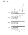
- Fig. 4 is schematic enlarged sectional drawings of the vicinity of the inlet side end face B of a honeycomb structure 21.
- a condition of no generation of shrunk dent, shown in Fig. 4(i) was expressed as A; a condition of generation of small shrunk dent 28 but no practical problem, shown in Fig. 4(ii) was expressed as B; a condition of no generation of shrunk dent but rounded end of plugged portion 22 (resulting in reduced area of contact with cell 23), shown in Fig. 4(iii) was expressed as C; and a condition of generation of shrunk dent 26, shown in Fig. 4(iv) was expressed as D. Also, a very good condition was expressed as ⁇ ; a good condition was expressed as ⁇ ; and an inferior condition was expressed as X.
Landscapes
- Engineering & Computer Science (AREA)
- Chemical & Material Sciences (AREA)
- Ceramic Engineering (AREA)
- Manufacturing & Machinery (AREA)
- Structural Engineering (AREA)
- Inorganic Chemistry (AREA)
- Materials Engineering (AREA)
- Organic Chemistry (AREA)
- Mechanical Engineering (AREA)
- Chemical Kinetics & Catalysis (AREA)
- Physics & Mathematics (AREA)
- Thermal Sciences (AREA)
- Filtering Materials (AREA)
- Devices For Post-Treatments, Processing, Supply, Discharge, And Other Processes (AREA)
- Processes For Solid Components From Exhaust (AREA)
- Filtering Of Dispersed Particles In Gases (AREA)
Claims (5)
- Verfahren zur Herstellung einer Wabenstruktur, wobei das Verfahren Folgendes umfasst:das Aufbringen einer Abdeckung (11) auf einigen Zellen (23) an einer Endfläche einer Keramikwabenstruktur (1, 21) mit einer Vielzahl von Zellen (23), die jeweils als Flüssigkeitsdurchlass dienen;das Eintauchen der Endfläche der Keramikwabenstruktur in eine Aufschlämmung (10), die zumindest ein Keramikpulver, ein Dispersionsmedium und ein Bindemittel enthält, um die Aufschlämmung in die Zellen (23) ohne Abdeckung (11) zu drücken, um verschlossene Abschnitte (22) darin zu bilden; unddas Trocknen der verschlossenen Abschnitte (22), um eine Wabenstruktur (1, 21) zu erhalten, worin die Zellen (23) ohne Abdeckung (11) verschlossen sind;dadurch gekennzeichnet, dass das Trocknen der verschlossenen Abschnitte (22) durch eine Wärmeleitungsvorrichtung (12) erfolgt.
- Verfahren zur Herstellung einer Wabenstruktur nach Anspruch 1, worin die Wärmeleitungsvorrichtung (12) eine elektrische Heizplatte ist.
- Verfahren zur Herstellung einer Wabenstruktur nach Anspruch 1 oder 2, worin die Abdeckung (11) eine Dicke von 0,03 bis 0,5 mm aufweist.
- Verfahren zur Herstellung einer Wabenstruktur nach einem der Ansprüche 1 bis 3, worin das in der Aufschlämmung (10) enthaltene Bindemittel ein durch Wärme in den Gelzustand übergehendes Bindemittel ist.
- Verfahren zur Herstellung einer Wabenstruktur nach einem der Ansprüche 1 bis 4, worin die Aufschlämmung (10) eine Viskosität von 50 bis 500 dPa·s aufweist.
Applications Claiming Priority (3)
| Application Number | Priority Date | Filing Date | Title |
|---|---|---|---|
| JP2002144147 | 2002-05-20 | ||
| JP2002144147A JP4112899B2 (ja) | 2002-05-20 | 2002-05-20 | ハニカム構造体の製造方法 |
| PCT/JP2003/006201 WO2003097314A1 (en) | 2002-05-20 | 2003-05-19 | Method of manufacturing honeycomb structural body |
Publications (3)
| Publication Number | Publication Date |
|---|---|
| EP1508416A1 EP1508416A1 (de) | 2005-02-23 |
| EP1508416A4 EP1508416A4 (de) | 2005-11-16 |
| EP1508416B1 true EP1508416B1 (de) | 2008-09-10 |
Family
ID=29545047
Family Applications (1)
| Application Number | Title | Priority Date | Filing Date |
|---|---|---|---|
| EP03730511A Expired - Lifetime EP1508416B1 (de) | 2002-05-20 | 2003-05-19 | Verfahren zur herstellung eines wabensturkturkörpers |
Country Status (8)
| Country | Link |
|---|---|
| US (1) | US20040198599A1 (de) |
| EP (1) | EP1508416B1 (de) |
| JP (1) | JP4112899B2 (de) |
| CN (1) | CN1307030C (de) |
| AU (1) | AU2003242322A1 (de) |
| DE (1) | DE60323485D1 (de) |
| WO (1) | WO2003097314A1 (de) |
| ZA (1) | ZA200401191B (de) |
Cited By (1)
| Publication number | Priority date | Publication date | Assignee | Title |
|---|---|---|---|---|
| US8808601B2 (en) | 2008-05-30 | 2014-08-19 | Corning Incorporated | Method for manufacturing ceramic filter |
Families Citing this family (16)
| Publication number | Priority date | Publication date | Assignee | Title |
|---|---|---|---|---|
| JP2004290766A (ja) * | 2003-03-26 | 2004-10-21 | Ngk Insulators Ltd | ハニカム構造体の製造方法 |
| JP5090743B2 (ja) * | 2004-12-08 | 2012-12-05 | 日本碍子株式会社 | 目封止ハニカム構造体の製造方法 |
| JP4927405B2 (ja) * | 2005-03-23 | 2012-05-09 | 日本碍子株式会社 | 目封止ハニカム構造体の製造方法 |
| JP4632124B2 (ja) * | 2005-03-29 | 2011-02-16 | 日立金属株式会社 | セラミックハニカムフィルタの製造方法 |
| JP2007117817A (ja) * | 2005-10-26 | 2007-05-17 | Hitachi Metals Ltd | セラミックハニカムフィルタの目封止材料および目封止方法 |
| JP4948193B2 (ja) * | 2006-02-24 | 2012-06-06 | イビデン株式会社 | ハニカム集合体の端面乾燥方法、及び、ハニカム構造体の製造方法 |
| WO2008027301A2 (en) * | 2006-08-29 | 2008-03-06 | Corning Incorporated | Single fire honeycomb structure and method for manufacturing same |
| JP2008056528A (ja) * | 2006-08-31 | 2008-03-13 | Denso Corp | 栓詰め用スラリー及び栓詰めハニカム体の製造方法 |
| CN101384327B (zh) * | 2006-09-28 | 2012-07-18 | 日立金属株式会社 | 陶瓷蜂窝式过滤器的制造方法 |
| EP2116520B1 (de) * | 2007-01-18 | 2012-08-15 | NGK Insulators, Ltd. | Verfahren zur herstellung eines wabensegment-verbundkörpers |
| WO2009073094A2 (en) * | 2007-11-30 | 2009-06-11 | Corning Incorporated | Method of plugging honeycomb bodies |
| JP5787272B2 (ja) * | 2011-04-01 | 2015-09-30 | 日立金属株式会社 | セラミックハニカムフィルタの製造方法 |
| WO2014054168A1 (ja) * | 2012-10-05 | 2014-04-10 | イビデン株式会社 | ハニカム乾燥体の切断方法、ハニカム構造体の製造方法、ハニカム乾燥体、及び、ハニカム構造体 |
| CN104441322B (zh) * | 2014-11-14 | 2018-01-26 | 安徽金诚复合材料有限公司 | 防止芳纶蜂窝浸胶变形的装置 |
| CN105459255B (zh) * | 2015-11-20 | 2017-11-17 | 福州大学 | 一种陶瓷坯体钻孔的方法 |
| CN109476039A (zh) * | 2016-07-13 | 2019-03-15 | 康宁股份有限公司 | 对陶瓷蜂窝体进行堵塞的系统和方法 |
Family Cites Families (6)
| Publication number | Priority date | Publication date | Assignee | Title |
|---|---|---|---|---|
| JPS5954682A (ja) * | 1982-09-20 | 1984-03-29 | 日本碍子株式会社 | セラミツクハニカム構造体の開口端面封止方法 |
| JPS62144726A (ja) * | 1985-12-19 | 1987-06-27 | Ngk Insulators Ltd | セラミツクハニカム構造体の開口端面封止体の製造方法 |
| JPH061150B2 (ja) * | 1986-12-27 | 1994-01-05 | 日本碍子株式会社 | ハニカム構造体の誘電乾燥法 |
| JP2000280222A (ja) * | 1999-03-29 | 2000-10-10 | Ibiden Co Ltd | セラミック成形体の封口方法 |
| JP2001130970A (ja) * | 1999-08-24 | 2001-05-15 | Ibiden Co Ltd | セラミック成形体の乾燥方法 |
| US6849222B2 (en) * | 2000-05-12 | 2005-02-01 | Denso Corporation | Method of manufacturing ceramic honeycomb structure and device for forming through holes |
-
2002
- 2002-05-20 JP JP2002144147A patent/JP4112899B2/ja not_active Expired - Lifetime
-
2003
- 2003-05-19 WO PCT/JP2003/006201 patent/WO2003097314A1/ja not_active Ceased
- 2003-05-19 AU AU2003242322A patent/AU2003242322A1/en not_active Abandoned
- 2003-05-19 EP EP03730511A patent/EP1508416B1/de not_active Expired - Lifetime
- 2003-05-19 CN CNB038010518A patent/CN1307030C/zh not_active Expired - Lifetime
- 2003-05-19 DE DE60323485T patent/DE60323485D1/de not_active Expired - Lifetime
- 2003-05-19 US US10/486,545 patent/US20040198599A1/en not_active Abandoned
-
2004
- 2004-02-13 ZA ZA200401191A patent/ZA200401191B/en unknown
Cited By (1)
| Publication number | Priority date | Publication date | Assignee | Title |
|---|---|---|---|---|
| US8808601B2 (en) | 2008-05-30 | 2014-08-19 | Corning Incorporated | Method for manufacturing ceramic filter |
Also Published As
| Publication number | Publication date |
|---|---|
| US20040198599A1 (en) | 2004-10-07 |
| EP1508416A1 (de) | 2005-02-23 |
| JP4112899B2 (ja) | 2008-07-02 |
| JP2003334810A (ja) | 2003-11-25 |
| EP1508416A4 (de) | 2005-11-16 |
| WO2003097314A1 (en) | 2003-11-27 |
| DE60323485D1 (de) | 2008-10-23 |
| AU2003242322A1 (en) | 2003-12-02 |
| ZA200401191B (en) | 2005-02-14 |
| CN1307030C (zh) | 2007-03-28 |
| CN1556741A (zh) | 2004-12-22 |
Similar Documents
| Publication | Publication Date | Title |
|---|---|---|
| EP1508416B1 (de) | Verfahren zur herstellung eines wabensturkturkörpers | |
| EP1516658B1 (de) | Verfahren zur herstellung von wabenstrukturen | |
| EP1607130B1 (de) | Abgedichtete wabenstruktur und herstellungsverfahren dafür | |
| EP1696109B1 (de) | Herstellungsverfahren für eine abgedichtete Wabenstruktur | |
| EP1413345B1 (de) | Wabenstrukturkörper und verfahren zur herstellung des sturkturkörpers | |
| JP4266103B2 (ja) | 多孔質セラミック体の製造方法 | |
| EP1857427B1 (de) | Wabenstruktur und herstellungsverfahren dafür | |
| US7578864B2 (en) | Ceramic honeycomb filter and its production method | |
| US7537634B2 (en) | Method for manufacturing plugged honeycomb structure | |
| US8729436B2 (en) | Drying process and apparatus for ceramic greenware | |
| WO2003067041A1 (en) | Honeycomb filter for exhaust gas decontamination, adhesive, coating material and process for producing honeycomb filter for exhaust gas decontamination | |
| JPS6324731B2 (de) | ||
| JP2002159811A (ja) | ハニカムフィルター及びその製造方法 | |
| JPWO2008117621A1 (ja) | セラミックハニカム構造体の製造方法 | |
| EP2006266A1 (de) | Wabenstruktur, herstellungsverfahren dafür und verbindungsmaterial | |
| EP1559878B1 (de) | Wabenstruktur | |
| JP4511103B2 (ja) | 複合材料の製造方法 | |
| JP3385807B2 (ja) | 排ガスフィルタ及びその製造方法 | |
| KR102611477B1 (ko) | 비상발전기용 매연저감필터 | |
| KR20080046029A (ko) | 허니콤 필터용 세라믹 밀봉재 | |
| JPH08189338A (ja) | ディーゼル排気ガスフィルタの製造方法 |
Legal Events
| Date | Code | Title | Description |
|---|---|---|---|
| PUAI | Public reference made under article 153(3) epc to a published international application that has entered the european phase |
Free format text: ORIGINAL CODE: 0009012 |
|
| 17P | Request for examination filed |
Effective date: 20040301 |
|
| AK | Designated contracting states |
Kind code of ref document: A1 Designated state(s): AT BE BG CH CY CZ DE DK EE ES FI FR GB GR HU IE IT LI LU MC NL PT RO SE SI SK TR |
|
| AX | Request for extension of the european patent |
Extension state: AL LT LV MK |
|
| DAX | Request for extension of the european patent (deleted) | ||
| RBV | Designated contracting states (corrected) |
Designated state(s): BE DE |
|
| A4 | Supplementary search report drawn up and despatched |
Effective date: 20050930 |
|
| GRAP | Despatch of communication of intention to grant a patent |
Free format text: ORIGINAL CODE: EPIDOSNIGR1 |
|
| GRAS | Grant fee paid |
Free format text: ORIGINAL CODE: EPIDOSNIGR3 |
|
| GRAA | (expected) grant |
Free format text: ORIGINAL CODE: 0009210 |
|
| RAP1 | Party data changed (applicant data changed or rights of an application transferred) |
Owner name: NGK INSULATORS, LTD. |
|
| AK | Designated contracting states |
Kind code of ref document: B1 Designated state(s): BE DE |
|
| REF | Corresponds to: |
Ref document number: 60323485 Country of ref document: DE Date of ref document: 20081023 Kind code of ref document: P |
|
| PLBE | No opposition filed within time limit |
Free format text: ORIGINAL CODE: 0009261 |
|
| STAA | Information on the status of an ep patent application or granted ep patent |
Free format text: STATUS: NO OPPOSITION FILED WITHIN TIME LIMIT |
|
| 26N | No opposition filed |
Effective date: 20090611 |
|
| PGFP | Annual fee paid to national office [announced via postgrant information from national office to epo] |
Ref country code: BE Payment date: 20090512 Year of fee payment: 7 |
|
| BERE | Be: lapsed |
Owner name: NGK INSULATORS, LTD. Effective date: 20100531 |
|
| PG25 | Lapsed in a contracting state [announced via postgrant information from national office to epo] |
Ref country code: BE Free format text: LAPSE BECAUSE OF NON-PAYMENT OF DUE FEES Effective date: 20100531 |
|
| PGFP | Annual fee paid to national office [announced via postgrant information from national office to epo] |
Ref country code: DE Payment date: 20220329 Year of fee payment: 20 |
|
| REG | Reference to a national code |
Ref country code: DE Ref legal event code: R071 Ref document number: 60323485 Country of ref document: DE |