EP1508675B1 - Mehrzylindrige Diesel-Brennkraftmaschine mit variabler Ventilsteuerung - Google Patents
Mehrzylindrige Diesel-Brennkraftmaschine mit variabler Ventilsteuerung Download PDFInfo
- Publication number
- EP1508675B1 EP1508675B1 EP04024257A EP04024257A EP1508675B1 EP 1508675 B1 EP1508675 B1 EP 1508675B1 EP 04024257 A EP04024257 A EP 04024257A EP 04024257 A EP04024257 A EP 04024257A EP 1508675 B1 EP1508675 B1 EP 1508675B1
- Authority
- EP
- European Patent Office
- Prior art keywords
- valve
- cylinder
- exhaust
- engine
- inlet
- Prior art date
- Legal status (The legal status is an assumption and is not a legal conclusion. Google has not performed a legal analysis and makes no representation as to the accuracy of the status listed.)
- Expired - Lifetime
Links
Images


Classifications
-
- F—MECHANICAL ENGINEERING; LIGHTING; HEATING; WEAPONS; BLASTING
- F02—COMBUSTION ENGINES; HOT-GAS OR COMBUSTION-PRODUCT ENGINE PLANTS
- F02D—CONTROLLING COMBUSTION ENGINES
- F02D13/00—Controlling the engine output power by varying inlet or exhaust valve operating characteristics, e.g. timing
- F02D13/02—Controlling the engine output power by varying inlet or exhaust valve operating characteristics, e.g. timing during engine operation
- F02D13/0253—Fully variable control of valve lift and timing using camless actuation systems such as hydraulic, pneumatic or electromagnetic actuators, e.g. solenoid valves
-
- F—MECHANICAL ENGINEERING; LIGHTING; HEATING; WEAPONS; BLASTING
- F01—MACHINES OR ENGINES IN GENERAL; ENGINE PLANTS IN GENERAL; STEAM ENGINES
- F01L—CYCLICALLY OPERATING VALVES FOR MACHINES OR ENGINES
- F01L1/00—Valve-gear or valve arrangements, e.g. lift-valve gear
- F01L1/02—Valve drive
- F01L1/04—Valve drive by means of cams, camshafts, cam discs, eccentrics or the like
- F01L1/08—Shape of cams
-
- F—MECHANICAL ENGINEERING; LIGHTING; HEATING; WEAPONS; BLASTING
- F01—MACHINES OR ENGINES IN GENERAL; ENGINE PLANTS IN GENERAL; STEAM ENGINES
- F01L—CYCLICALLY OPERATING VALVES FOR MACHINES OR ENGINES
- F01L1/00—Valve-gear or valve arrangements, e.g. lift-valve gear
- F01L1/26—Valve-gear or valve arrangements, e.g. lift-valve gear characterised by the provision of two or more valves operated simultaneously by same transmitting-gear; peculiar to machines or engines with more than two lift-valves per cylinder
-
- F—MECHANICAL ENGINEERING; LIGHTING; HEATING; WEAPONS; BLASTING
- F01—MACHINES OR ENGINES IN GENERAL; ENGINE PLANTS IN GENERAL; STEAM ENGINES
- F01L—CYCLICALLY OPERATING VALVES FOR MACHINES OR ENGINES
- F01L13/00—Modifications of valve-gear to facilitate reversing, braking, starting, changing compression ratio, or other specific operations
- F01L13/0005—Deactivating valves
-
- F—MECHANICAL ENGINEERING; LIGHTING; HEATING; WEAPONS; BLASTING
- F01—MACHINES OR ENGINES IN GENERAL; ENGINE PLANTS IN GENERAL; STEAM ENGINES
- F01L—CYCLICALLY OPERATING VALVES FOR MACHINES OR ENGINES
- F01L9/00—Valve-gear or valve arrangements actuated non-mechanically
- F01L9/10—Valve-gear or valve arrangements actuated non-mechanically by fluid means, e.g. hydraulic
- F01L9/11—Valve-gear or valve arrangements actuated non-mechanically by fluid means, e.g. hydraulic in which the action of a cam is being transmitted to a valve by a liquid column
-
- F—MECHANICAL ENGINEERING; LIGHTING; HEATING; WEAPONS; BLASTING
- F01—MACHINES OR ENGINES IN GENERAL; ENGINE PLANTS IN GENERAL; STEAM ENGINES
- F01L—CYCLICALLY OPERATING VALVES FOR MACHINES OR ENGINES
- F01L9/00—Valve-gear or valve arrangements actuated non-mechanically
- F01L9/10—Valve-gear or valve arrangements actuated non-mechanically by fluid means, e.g. hydraulic
- F01L9/11—Valve-gear or valve arrangements actuated non-mechanically by fluid means, e.g. hydraulic in which the action of a cam is being transmitted to a valve by a liquid column
- F01L9/12—Valve-gear or valve arrangements actuated non-mechanically by fluid means, e.g. hydraulic in which the action of a cam is being transmitted to a valve by a liquid column with a liquid chamber between a piston actuated by a cam and a piston acting on a valve stem
- F01L9/14—Valve-gear or valve arrangements actuated non-mechanically by fluid means, e.g. hydraulic in which the action of a cam is being transmitted to a valve by a liquid column with a liquid chamber between a piston actuated by a cam and a piston acting on a valve stem the volume of the chamber being variable, e.g. for varying the lift or the timing of a valve
-
- F—MECHANICAL ENGINEERING; LIGHTING; HEATING; WEAPONS; BLASTING
- F02—COMBUSTION ENGINES; HOT-GAS OR COMBUSTION-PRODUCT ENGINE PLANTS
- F02B—INTERNAL-COMBUSTION PISTON ENGINES; COMBUSTION ENGINES IN GENERAL
- F02B17/00—Engines characterised by means for effecting stratification of charge in cylinders
- F02B17/005—Engines characterised by means for effecting stratification of charge in cylinders having direct injection in the combustion chamber
-
- F—MECHANICAL ENGINEERING; LIGHTING; HEATING; WEAPONS; BLASTING
- F02—COMBUSTION ENGINES; HOT-GAS OR COMBUSTION-PRODUCT ENGINE PLANTS
- F02B—INTERNAL-COMBUSTION PISTON ENGINES; COMBUSTION ENGINES IN GENERAL
- F02B31/00—Modifying induction systems for imparting a rotation to the charge in the cylinder
- F02B31/04—Modifying induction systems for imparting a rotation to the charge in the cylinder by means within the induction channel, e.g. deflectors
- F02B31/042—Modifying induction systems for imparting a rotation to the charge in the cylinder by means within the induction channel, e.g. deflectors induction channel having a helical shape around the intake valve axis
-
- F—MECHANICAL ENGINEERING; LIGHTING; HEATING; WEAPONS; BLASTING
- F02—COMBUSTION ENGINES; HOT-GAS OR COMBUSTION-PRODUCT ENGINE PLANTS
- F02B—INTERNAL-COMBUSTION PISTON ENGINES; COMBUSTION ENGINES IN GENERAL
- F02B31/00—Modifying induction systems for imparting a rotation to the charge in the cylinder
- F02B31/08—Modifying induction systems for imparting a rotation to the charge in the cylinder having multiple air inlets
- F02B31/085—Modifying induction systems for imparting a rotation to the charge in the cylinder having multiple air inlets having two inlet valves
-
- F—MECHANICAL ENGINEERING; LIGHTING; HEATING; WEAPONS; BLASTING
- F02—COMBUSTION ENGINES; HOT-GAS OR COMBUSTION-PRODUCT ENGINE PLANTS
- F02B—INTERNAL-COMBUSTION PISTON ENGINES; COMBUSTION ENGINES IN GENERAL
- F02B47/00—Methods of operating engines involving adding non-fuel substances or anti-knock agents to combustion air, fuel, or fuel-air mixtures of engines
- F02B47/04—Methods of operating engines involving adding non-fuel substances or anti-knock agents to combustion air, fuel, or fuel-air mixtures of engines the substances being other than water or steam only
- F02B47/08—Methods of operating engines involving adding non-fuel substances or anti-knock agents to combustion air, fuel, or fuel-air mixtures of engines the substances being other than water or steam only the substances including exhaust gas
-
- F—MECHANICAL ENGINEERING; LIGHTING; HEATING; WEAPONS; BLASTING
- F02—COMBUSTION ENGINES; HOT-GAS OR COMBUSTION-PRODUCT ENGINE PLANTS
- F02B—INTERNAL-COMBUSTION PISTON ENGINES; COMBUSTION ENGINES IN GENERAL
- F02B75/00—Other engines
- F02B75/16—Engines characterised by number of cylinders, e.g. single-cylinder engines
- F02B75/18—Multi-cylinder engines
- F02B75/20—Multi-cylinder engines with cylinders all in one line
-
- F—MECHANICAL ENGINEERING; LIGHTING; HEATING; WEAPONS; BLASTING
- F02—COMBUSTION ENGINES; HOT-GAS OR COMBUSTION-PRODUCT ENGINE PLANTS
- F02D—CONTROLLING COMBUSTION ENGINES
- F02D13/00—Controlling the engine output power by varying inlet or exhaust valve operating characteristics, e.g. timing
- F02D13/02—Controlling the engine output power by varying inlet or exhaust valve operating characteristics, e.g. timing during engine operation
- F02D13/0203—Variable control of intake and exhaust valves
- F02D13/0207—Variable control of intake and exhaust valves changing valve lift or valve lift and timing
-
- F—MECHANICAL ENGINEERING; LIGHTING; HEATING; WEAPONS; BLASTING
- F02—COMBUSTION ENGINES; HOT-GAS OR COMBUSTION-PRODUCT ENGINE PLANTS
- F02D—CONTROLLING COMBUSTION ENGINES
- F02D13/00—Controlling the engine output power by varying inlet or exhaust valve operating characteristics, e.g. timing
- F02D13/02—Controlling the engine output power by varying inlet or exhaust valve operating characteristics, e.g. timing during engine operation
- F02D13/0257—Independent control of two or more intake or exhaust valves respectively, i.e. one of two intake valves remains closed or is opened partially while the other is fully opened
-
- F—MECHANICAL ENGINEERING; LIGHTING; HEATING; WEAPONS; BLASTING
- F02—COMBUSTION ENGINES; HOT-GAS OR COMBUSTION-PRODUCT ENGINE PLANTS
- F02D—CONTROLLING COMBUSTION ENGINES
- F02D13/00—Controlling the engine output power by varying inlet or exhaust valve operating characteristics, e.g. timing
- F02D13/02—Controlling the engine output power by varying inlet or exhaust valve operating characteristics, e.g. timing during engine operation
- F02D13/0273—Multiple actuations of a valve within an engine cycle
-
- F—MECHANICAL ENGINEERING; LIGHTING; HEATING; WEAPONS; BLASTING
- F02—COMBUSTION ENGINES; HOT-GAS OR COMBUSTION-PRODUCT ENGINE PLANTS
- F02D—CONTROLLING COMBUSTION ENGINES
- F02D13/00—Controlling the engine output power by varying inlet or exhaust valve operating characteristics, e.g. timing
- F02D13/02—Controlling the engine output power by varying inlet or exhaust valve operating characteristics, e.g. timing during engine operation
- F02D13/0276—Actuation of an additional valve for a special application, e.g. for decompression, exhaust gas recirculation or cylinder scavenging
-
- F—MECHANICAL ENGINEERING; LIGHTING; HEATING; WEAPONS; BLASTING
- F02—COMBUSTION ENGINES; HOT-GAS OR COMBUSTION-PRODUCT ENGINE PLANTS
- F02D—CONTROLLING COMBUSTION ENGINES
- F02D13/00—Controlling the engine output power by varying inlet or exhaust valve operating characteristics, e.g. timing
- F02D13/02—Controlling the engine output power by varying inlet or exhaust valve operating characteristics, e.g. timing during engine operation
- F02D13/04—Controlling the engine output power by varying inlet or exhaust valve operating characteristics, e.g. timing during engine operation using engine as brake
-
- F—MECHANICAL ENGINEERING; LIGHTING; HEATING; WEAPONS; BLASTING
- F02—COMBUSTION ENGINES; HOT-GAS OR COMBUSTION-PRODUCT ENGINE PLANTS
- F02D—CONTROLLING COMBUSTION ENGINES
- F02D41/00—Electrical control of supply of combustible mixture or its constituents
- F02D41/0025—Controlling engines characterised by use of non-liquid fuels, pluralities of fuels, or non-fuel substances added to the combustible mixtures
- F02D41/0047—Controlling exhaust gas recirculation [EGR]
- F02D41/006—Controlling exhaust gas recirculation [EGR] using internal EGR
-
- F—MECHANICAL ENGINEERING; LIGHTING; HEATING; WEAPONS; BLASTING
- F02—COMBUSTION ENGINES; HOT-GAS OR COMBUSTION-PRODUCT ENGINE PLANTS
- F02F—CYLINDERS, PISTONS OR CASINGS, FOR COMBUSTION ENGINES; ARRANGEMENTS OF SEALINGS IN COMBUSTION ENGINES
- F02F1/00—Cylinders; Cylinder heads
- F02F1/24—Cylinder heads
- F02F1/42—Shape or arrangement of intake or exhaust channels in cylinder heads
- F02F1/4214—Shape or arrangement of intake or exhaust channels in cylinder heads specially adapted for four or more valves per cylinder
-
- F—MECHANICAL ENGINEERING; LIGHTING; HEATING; WEAPONS; BLASTING
- F02—COMBUSTION ENGINES; HOT-GAS OR COMBUSTION-PRODUCT ENGINE PLANTS
- F02M—SUPPLYING COMBUSTION ENGINES IN GENERAL WITH COMBUSTIBLE MIXTURES OR CONSTITUENTS THEREOF
- F02M26/00—Engine-pertinent apparatus for adding exhaust gases to combustion-air, main fuel or fuel-air mixture, e.g. by exhaust gas recirculation [EGR] systems
- F02M26/01—Internal exhaust gas recirculation, i.e. wherein the residual exhaust gases are trapped in the cylinder or pushed back from the intake or the exhaust manifold into the combustion chamber without the use of additional passages
-
- F—MECHANICAL ENGINEERING; LIGHTING; HEATING; WEAPONS; BLASTING
- F01—MACHINES OR ENGINES IN GENERAL; ENGINE PLANTS IN GENERAL; STEAM ENGINES
- F01L—CYCLICALLY OPERATING VALVES FOR MACHINES OR ENGINES
- F01L1/00—Valve-gear or valve arrangements, e.g. lift-valve gear
- F01L1/26—Valve-gear or valve arrangements, e.g. lift-valve gear characterised by the provision of two or more valves operated simultaneously by same transmitting-gear; peculiar to machines or engines with more than two lift-valves per cylinder
- F01L1/267—Valve-gear or valve arrangements, e.g. lift-valve gear characterised by the provision of two or more valves operated simultaneously by same transmitting-gear; peculiar to machines or engines with more than two lift-valves per cylinder with means for varying the timing or the lift of the valves
-
- F—MECHANICAL ENGINEERING; LIGHTING; HEATING; WEAPONS; BLASTING
- F01—MACHINES OR ENGINES IN GENERAL; ENGINE PLANTS IN GENERAL; STEAM ENGINES
- F01L—CYCLICALLY OPERATING VALVES FOR MACHINES OR ENGINES
- F01L1/00—Valve-gear or valve arrangements, e.g. lift-valve gear
- F01L1/02—Valve drive
- F01L1/04—Valve drive by means of cams, camshafts, cam discs, eccentrics or the like
- F01L1/047—Camshafts
- F01L1/053—Camshafts overhead type
- F01L2001/0535—Single overhead camshafts [SOHC]
-
- F—MECHANICAL ENGINEERING; LIGHTING; HEATING; WEAPONS; BLASTING
- F01—MACHINES OR ENGINES IN GENERAL; ENGINE PLANTS IN GENERAL; STEAM ENGINES
- F01L—CYCLICALLY OPERATING VALVES FOR MACHINES OR ENGINES
- F01L1/00—Valve-gear or valve arrangements, e.g. lift-valve gear
- F01L1/02—Valve drive
- F01L1/04—Valve drive by means of cams, camshafts, cam discs, eccentrics or the like
- F01L1/047—Camshafts
- F01L1/053—Camshafts overhead type
- F01L2001/0537—Double overhead camshafts [DOHC]
-
- F—MECHANICAL ENGINEERING; LIGHTING; HEATING; WEAPONS; BLASTING
- F01—MACHINES OR ENGINES IN GENERAL; ENGINE PLANTS IN GENERAL; STEAM ENGINES
- F01L—CYCLICALLY OPERATING VALVES FOR MACHINES OR ENGINES
- F01L1/00—Valve-gear or valve arrangements, e.g. lift-valve gear
- F01L1/34—Valve-gear or valve arrangements, e.g. lift-valve gear characterised by the provision of means for changing the timing of the valves without changing the duration of opening and without affecting the magnitude of the valve lift
- F01L1/344—Valve-gear or valve arrangements, e.g. lift-valve gear characterised by the provision of means for changing the timing of the valves without changing the duration of opening and without affecting the magnitude of the valve lift changing the angular relationship between crankshaft and camshaft, e.g. using helicoidal gear
- F01L1/3442—Valve-gear or valve arrangements, e.g. lift-valve gear characterised by the provision of means for changing the timing of the valves without changing the duration of opening and without affecting the magnitude of the valve lift changing the angular relationship between crankshaft and camshaft, e.g. using helicoidal gear using hydraulic chambers with variable volume to transmit the rotating force
- F01L2001/34423—Details relating to the hydraulic feeding circuit
- F01L2001/34446—Fluid accumulators for the feeding circuit
-
- F—MECHANICAL ENGINEERING; LIGHTING; HEATING; WEAPONS; BLASTING
- F01—MACHINES OR ENGINES IN GENERAL; ENGINE PLANTS IN GENERAL; STEAM ENGINES
- F01L—CYCLICALLY OPERATING VALVES FOR MACHINES OR ENGINES
- F01L2800/00—Methods of operation using a variable valve timing mechanism
-
- F—MECHANICAL ENGINEERING; LIGHTING; HEATING; WEAPONS; BLASTING
- F02—COMBUSTION ENGINES; HOT-GAS OR COMBUSTION-PRODUCT ENGINE PLANTS
- F02B—INTERNAL-COMBUSTION PISTON ENGINES; COMBUSTION ENGINES IN GENERAL
- F02B1/00—Engines characterised by fuel-air mixture compression
- F02B1/12—Engines characterised by fuel-air mixture compression with compression ignition
-
- F—MECHANICAL ENGINEERING; LIGHTING; HEATING; WEAPONS; BLASTING
- F02—COMBUSTION ENGINES; HOT-GAS OR COMBUSTION-PRODUCT ENGINE PLANTS
- F02B—INTERNAL-COMBUSTION PISTON ENGINES; COMBUSTION ENGINES IN GENERAL
- F02B2275/00—Other engines, components or details, not provided for in other groups of this subclass
- F02B2275/18—DOHC [Double overhead camshaft]
-
- F—MECHANICAL ENGINEERING; LIGHTING; HEATING; WEAPONS; BLASTING
- F02—COMBUSTION ENGINES; HOT-GAS OR COMBUSTION-PRODUCT ENGINE PLANTS
- F02B—INTERNAL-COMBUSTION PISTON ENGINES; COMBUSTION ENGINES IN GENERAL
- F02B2275/00—Other engines, components or details, not provided for in other groups of this subclass
- F02B2275/20—SOHC [Single overhead camshaft]
-
- F—MECHANICAL ENGINEERING; LIGHTING; HEATING; WEAPONS; BLASTING
- F02—COMBUSTION ENGINES; HOT-GAS OR COMBUSTION-PRODUCT ENGINE PLANTS
- F02B—INTERNAL-COMBUSTION PISTON ENGINES; COMBUSTION ENGINES IN GENERAL
- F02B2275/00—Other engines, components or details, not provided for in other groups of this subclass
- F02B2275/32—Miller cycle
-
- F—MECHANICAL ENGINEERING; LIGHTING; HEATING; WEAPONS; BLASTING
- F02—COMBUSTION ENGINES; HOT-GAS OR COMBUSTION-PRODUCT ENGINE PLANTS
- F02B—INTERNAL-COMBUSTION PISTON ENGINES; COMBUSTION ENGINES IN GENERAL
- F02B23/00—Other engines characterised by special shape or construction of combustion chambers to improve operation
- F02B23/08—Other engines characterised by special shape or construction of combustion chambers to improve operation with positive ignition
- F02B23/10—Other engines characterised by special shape or construction of combustion chambers to improve operation with positive ignition with separate admission of air and fuel into cylinder
- F02B23/101—Other engines characterised by special shape or construction of combustion chambers to improve operation with positive ignition with separate admission of air and fuel into cylinder the injector being placed on or close to the cylinder centre axis, e.g. with mixture formation using spray guided concepts
-
- F—MECHANICAL ENGINEERING; LIGHTING; HEATING; WEAPONS; BLASTING
- F02—COMBUSTION ENGINES; HOT-GAS OR COMBUSTION-PRODUCT ENGINE PLANTS
- F02B—INTERNAL-COMBUSTION PISTON ENGINES; COMBUSTION ENGINES IN GENERAL
- F02B3/00—Engines characterised by air compression and subsequent fuel addition
- F02B3/06—Engines characterised by air compression and subsequent fuel addition with compression ignition
-
- F—MECHANICAL ENGINEERING; LIGHTING; HEATING; WEAPONS; BLASTING
- F02—COMBUSTION ENGINES; HOT-GAS OR COMBUSTION-PRODUCT ENGINE PLANTS
- F02D—CONTROLLING COMBUSTION ENGINES
- F02D13/00—Controlling the engine output power by varying inlet or exhaust valve operating characteristics, e.g. timing
- F02D13/02—Controlling the engine output power by varying inlet or exhaust valve operating characteristics, e.g. timing during engine operation
- F02D13/0269—Controlling the valves to perform a Miller-Atkinson cycle
-
- F—MECHANICAL ENGINEERING; LIGHTING; HEATING; WEAPONS; BLASTING
- F02—COMBUSTION ENGINES; HOT-GAS OR COMBUSTION-PRODUCT ENGINE PLANTS
- F02D—CONTROLLING COMBUSTION ENGINES
- F02D15/00—Varying compression ratio
- F02D15/04—Varying compression ratio by alteration of volume of compression space without changing piston stroke
-
- F—MECHANICAL ENGINEERING; LIGHTING; HEATING; WEAPONS; BLASTING
- F02—COMBUSTION ENGINES; HOT-GAS OR COMBUSTION-PRODUCT ENGINE PLANTS
- F02D—CONTROLLING COMBUSTION ENGINES
- F02D13/00—Controlling the engine output power by varying inlet or exhaust valve operating characteristics, e.g. timing
- F02D13/02—Controlling the engine output power by varying inlet or exhaust valve operating characteristics, e.g. timing during engine operation
- F02D2013/0292—Controlling the engine output power by varying inlet or exhaust valve operating characteristics, e.g. timing during engine operation in the start-up phase, e.g. for warming-up cold engine or catalyst
-
- F—MECHANICAL ENGINEERING; LIGHTING; HEATING; WEAPONS; BLASTING
- F02—COMBUSTION ENGINES; HOT-GAS OR COMBUSTION-PRODUCT ENGINE PLANTS
- F02D—CONTROLLING COMBUSTION ENGINES
- F02D41/00—Electrical control of supply of combustible mixture or its constituents
- F02D41/0002—Controlling intake air
- F02D2041/001—Controlling intake air for engines with variable valve actuation
-
- F—MECHANICAL ENGINEERING; LIGHTING; HEATING; WEAPONS; BLASTING
- F02—COMBUSTION ENGINES; HOT-GAS OR COMBUSTION-PRODUCT ENGINE PLANTS
- F02D—CONTROLLING COMBUSTION ENGINES
- F02D41/00—Electrical control of supply of combustible mixture or its constituents
- F02D41/30—Controlling fuel injection
- F02D41/3011—Controlling fuel injection according to or using specific or several modes of combustion
- F02D41/3017—Controlling fuel injection according to or using specific or several modes of combustion characterised by the mode(s) being used
- F02D41/3035—Controlling fuel injection according to or using specific or several modes of combustion characterised by the mode(s) being used a mode being the premixed charge compression-ignition mode
-
- F—MECHANICAL ENGINEERING; LIGHTING; HEATING; WEAPONS; BLASTING
- F02—COMBUSTION ENGINES; HOT-GAS OR COMBUSTION-PRODUCT ENGINE PLANTS
- F02F—CYLINDERS, PISTONS OR CASINGS, FOR COMBUSTION ENGINES; ARRANGEMENTS OF SEALINGS IN COMBUSTION ENGINES
- F02F1/00—Cylinders; Cylinder heads
- F02F1/24—Cylinder heads
- F02F2001/244—Arrangement of valve stems in cylinder heads
- F02F2001/247—Arrangement of valve stems in cylinder heads the valve stems being orientated in parallel with the cylinder axis
-
- Y—GENERAL TAGGING OF NEW TECHNOLOGICAL DEVELOPMENTS; GENERAL TAGGING OF CROSS-SECTIONAL TECHNOLOGIES SPANNING OVER SEVERAL SECTIONS OF THE IPC; TECHNICAL SUBJECTS COVERED BY FORMER USPC CROSS-REFERENCE ART COLLECTIONS [XRACs] AND DIGESTS
- Y02—TECHNOLOGIES OR APPLICATIONS FOR MITIGATION OR ADAPTATION AGAINST CLIMATE CHANGE
- Y02T—CLIMATE CHANGE MITIGATION TECHNOLOGIES RELATED TO TRANSPORTATION
- Y02T10/00—Road transport of goods or passengers
- Y02T10/10—Internal combustion engine [ICE] based vehicles
- Y02T10/12—Improving ICE efficiencies
-
- Y—GENERAL TAGGING OF NEW TECHNOLOGICAL DEVELOPMENTS; GENERAL TAGGING OF CROSS-SECTIONAL TECHNOLOGIES SPANNING OVER SEVERAL SECTIONS OF THE IPC; TECHNICAL SUBJECTS COVERED BY FORMER USPC CROSS-REFERENCE ART COLLECTIONS [XRACs] AND DIGESTS
- Y02—TECHNOLOGIES OR APPLICATIONS FOR MITIGATION OR ADAPTATION AGAINST CLIMATE CHANGE
- Y02T—CLIMATE CHANGE MITIGATION TECHNOLOGIES RELATED TO TRANSPORTATION
- Y02T10/00—Road transport of goods or passengers
- Y02T10/10—Internal combustion engine [ICE] based vehicles
- Y02T10/40—Engine management systems
Definitions
- the present invention relates to multi-cylinder Diesel engines of the type employing variably actuated valves.
- the object of the present invention is that of further perfecting the previously proposed engine for the purposes of achieving a series of advantages with regards to reducing harmful exhaust emissions and/or overcoming problems of cold starting or creating the so-called “blue smoke” in the "warm-up" phase after a cold start, and/or achieving improved performance and/or consumption reductions.
- internal EGR hot
- external EGR cooled
- internal EGR hot
- variable valve actuation system can accurately control high internal EGR doses and dilute the charge to render it almost stoichiometric, simultaneously controlling its temperature by mixing with external EGR (cold). This is extremely important because the temperature of the charge influences the ignition delay caused by the high rarefaction of the mixture and, thanks to the high concentration of active radicals present in hot EGR, it can accelerate the speed of combustion.
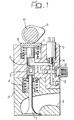
- FIG. 1 schematically illustrates the principle of operation of a variable valve actuation system in an internal combustion engine.
- Reference number 1 indicates the valve (which can be either an inlet valve or an exhaust valve) as a whole, associated with a respective port 2 (inlet or exhaust) formed inside the cylinder head 3 of an internal combustion engine.
- the valve 1 is drawn towards its closed position (upwards with reference to Figure 1) by a spring 4, while it is forced to open by a piston 5 acting on the upper end of the valve stem.
- the piston 5 is in turn controlled via oil under pressure that is present in the chamber 6, by a piston 7 that supports a spring cup 8 cooperating with a cam 9 on a camshaft 10.
- the spring cup 8 is held in sliding contact with the cam 9 by a spring 11.
- the pressure chamber 6 can be connected to a port 12, which in turn communicates with a pressure accumulator 13, via the shutter 14 of a solenoid valve 15 that is commanded by the electronic means of control (not illustrated) according to the engine's operating conditions.
- a solenoid valve 15 When the solenoid valve 15 is opened, oil under pressure inside the chamber 6 is discharged, causing the valve 1 to rapidly close under the effect of the return spring 4.
- the cam 9 normally controls the opening of the valve 1 according to a cycle that depends on the profile of the cam, but it can be "disabled” any time it is wished by opening the solenoid valve 15, thereby interrupting the connection between the piston 7 and the valve 1.
- the present invention refers to the application of the above described variable valve actuation system to a multi-cylinder Diesel engine, especially the type suited for utilization in automobiles, but also the application of any other type of variable valve actuation system with the same or similar characteristics.
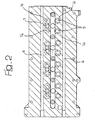
- FIGS 2 and 3 schematically illustrate the cylinder head of such an engine, incorporating two inlet valves V I and two exhaust valves V E for each cylinder.
- Each pair of exhaust valves V E is controlled by a single actuator piston 5 via a crosspiece 16, whilst the two inlet valves V I of each cylinder are controlled by separate actuator pistons 5.
- reference E indicates the two exhaust ports associated with each engine cylinder, while I 1 and I 2 indicate the inlet ports.
- the first inlet port I 1 is shaped to direct the flow of air entering the cylinder in a direction F 1 , substantially tangential with respect to the axis 17 of the cylinder.
- the second inlet port I 2 has instead a spiral shaped end section that generates an air vortex F 2 , rotating around an axis substantially parallel to the axis of the cylinder 17, at the entrance to the cylinder.
- Figures 6 and 7 are diagrams that illustrate the lift of the engine's inlet and exhaust valves, respectively indicated as A and S, corresponding to operating conditions suitable for realising "post-charging", as already illustrated in the foregoing, and to operating conditions suitable for realising internal EGR.
- the inlet and exhaust valve control cams have a main protuberance destined to realize the normal lifting of the valves during the normal induction and exhaust phases of the Diesel cycle, and an additional protuberance destined to realize a supplementary lift of the exhaust valve during the normal induction phase ( Figures 6 and 7) and of the inlet valve during the normal exhaust phase (see Figure 7).
- valve lift diagrams in Figures 6 and 7 are different, because the closure of the inlet valve can be advanced (see Figure 6) via the variable valve actuation system emptying the pressure chamber before the "natural" closure of the inlet valve, and because the supplementary exhaust valve opening phase during the induction phase can be varied in lift and duration, always as a result of the variable actuation of the valves (compare the S diagram to the right in Figures 6 and 7).
- the mode of operation that is realized with the valve lifts illustrated in Figure 6 allows a "post-charging" type of cycle to be achieved, where the additional opening of the exhaust valve during the last phase of induction ensures that part of the air entering the cylinder during the induction phase passes directly from the inlet port to the exhaust port, from where it is subsequently forced to return to the cylinder by the pressure wave created in the exhaust manifold due to the fact that another engine cylinder is in the exhaust phase, with the consequent advantage of improving engine breathing and increasing low-speed torque.
- the variable valve actuation system allows the inlet valve to be closed in a modifiable manner, with the aim of optimally exploiting the pressure wave that is created in the exhaust.
- a supplementary lift of the exhaust valve is always present during the final part of the induction phase, but with a different timing and duration of opening with respect to the case of supplementary lift illustrated in Figure 6.
- a supplementary lift of the inlet valve occurs during the initial part of the exhaust phase.
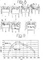
- Figure 8(A) illustrates the cylinder in the combustion phase, with the inlet and exhaust valves closed.
- Figure 8(B) illustrates the situation in the first part of the exhaust phase, with the inlet valve closed and the exhaust valve open. In this phase, the piston rises up expelling the combusted gases B through the exhaust port.
- Figure 8(C) illustrates the situation in a successive part of the exhaust phase, when the inlet valve has opened, in consequence of which a part B A of the combusted gases enters the inlet port and the inlet manifold.
- Figure 8(D) illustrates the situation immediately after the inlet valve closes during the exhaust phase. In this phase, a quantity B A of the combusted gases remains trapped in the inlet port, while the exhaust valve is always open to allow the discharge of the combusted gases.
- Figure 8(E) illustrates the successive, normal induction phase, in which the exhaust valve is closed and the inlet valve is open. In this phase, the quantity of exhaust gases B A that remained trapped in the inlet port re-enters the cylinder. The exhaust valve is closed.
- the supplementary opening of the exhaust valve ( Figure 8(F)) permits a second charge of combusted gas B S that was previously present in the exhaust port to re-enter the cylinder under the effect of the depression within the cylinder.
- Figure 8(G) illustrates the situation after closure of the inlet valve and the end of the supplementary exhaust valve opening phase, in which the two quantities of exhaust gas B A and B S are trapped within the cylinder, together with the charge of fresh air A.
- the combusted gases B A and B S participate in the combustion of the successive combustion phase, thereby realizing exhaust gas recirculation (EGR) inside the engine.
- EGR exhaust gas recirculation
- EGR allows fuel consumption and emissions to be reduced in cold-running conditions at low revs and loads.
- maximum efficiency of the system is achieved with the supplementary exhaust valve lift, which has different timing and duration in the case of post-charging ( Figure 6) and in the case of EGR ( Figure 7).
- the variable actuation of the valves allows regulation of exhaust valve closure as well as the timing and duration of the exhaust valve's supplementary opening.
- the realization of internal EGR in the mode of operation illustrated in Figure 7, is found to be particularly advantageous when used in combination with the inlet port geometry illustrated in Figures 4 and 5.
- the introduction of internal EGR via the reopening of the exhaust valve attenuates swirl in the cylinder due to the introduction of a mass of combusted gases with an angular motion that is null or low or in the opposite direction.
- the possibility of actuating the two inlet valves in a differentiated manner, in combination with the different geometry of the inlet ports I 1 and I 2 allows the swirl to be increased by counteracting or cancelling the aforesaid negative effect.
- the port I 1 generates high swirl from the first stages of opening in the induction phase, while port I 2 has the function of replenishment, only generating swirl in synergy with the first port I 1 .
- port I 2 has the function of replenishment, only generating swirl in synergy with the first port I 1 .
- This solution is definitely more effective than the traditional solution that uses a butterfly-valve choke in the inlet port, which does not guarantee perfect sealing and introduces secondary currents between the closed port and the cylinder.
- variable valve actuation system allows this negative effect to be minimised thanks to the possibility of partially opening the second inlet valve.
- this actuation opportunely timed and controlled, allows high swirl to be maintained inside the cylinder with smaller surge effect losses and gives rise to a better consumption/emission trade-off.
- variable valve actuation system allows this effect to be generated and optimised over a wider range of useful engine revs.
- the variable valve actuation device also provides the possibility of excluding the post exhaust valve lift at medium-high running conditions, where its presence is not desired or could be counterproductive.
- variable valve actuation system allows a lower geometric compression ratio (GCR) to be adopted, with corresponding benefits in terms of performance, as in clearly evident from the diagram in Figure 9, which shows the graph of effective mean pressure against engine speed for geometric compression ratios of 17:1 (upper curve) and 18:1 (lower curve).
- GCR geometric compression ratio
- Figure 9 shows the graph of effective mean pressure against engine speed for geometric compression ratios of 17:1 (upper curve) and 18:1 (lower curve).
- the variable valve actuation system provides the benefit of being able to perform engine starting with the inlet valves being closed at bottom dead centre, thereby exploiting all of the geometric compression ratio and avoiding problems of stalling and blue smoke due to low pressure and temperature levels. At maximum revs and loads, closure of the inlet valve is delayed until after bottom dead centre, while at intermediate speeds it is regulated to guarantee ignition, minimize temperature and reduce harmful emissions.
- the engine is controlled in a manner that raises the exhaust gas temperature for activating the post-treatment systems (catalysers and traps) on cold starts. This is achieved by advancing closure of the inlet valve to reduce the flow of air through the engine, and thus, for a given amount of heat transferred to the exhaust gas, to increase exhaust temperature. The same effect can also achieved by advancing the opening of the exhaust valve.
- control of the engine is provided for the purposes of realizing a HCCI type of combustion via internal EGR dosing, as has already been described in the foregoing.
- the system can be controlled to obtain charge homogeneity and stratification, closed-loop control of the engine, with the aid of an oxygen sensor positioned on the exhaust, and the transition from HCCI to normal combustion without any vehicle driveability problems.
- the engine can be controlled in a manner to minimize the compression pressure within the cylinder and, in consequence, torque oscillations on the engine shaft during the switch-off phase.
- internal EGR hot
- internal EGR hot
- internal EGR can be used to reduce nitrogen oxides during the first phases of engine warm-up after starting, where external EGR cannot be used due to its low temperature, resulting in excessive emission of carbon and hydrocarbon oxides.
Landscapes
- Engineering & Computer Science (AREA)
- Mechanical Engineering (AREA)
- General Engineering & Computer Science (AREA)
- Chemical & Material Sciences (AREA)
- Combustion & Propulsion (AREA)
- Electromagnetism (AREA)
- Physics & Mathematics (AREA)
- Valve Device For Special Equipments (AREA)
- Output Control And Ontrol Of Special Type Engine (AREA)
- Exhaust-Gas Circulating Devices (AREA)
- Electrical Control Of Air Or Fuel Supplied To Internal-Combustion Engine (AREA)
- Combustion Methods Of Internal-Combustion Engines (AREA)
- Exhaust Gas After Treatment (AREA)
- Combined Controls Of Internal Combustion Engines (AREA)
- Valve-Gear Or Valve Arrangements (AREA)
Claims (11)
- Mehrzylinderdieselmotor aufweisend:- zwei Einlassventile (VI) und zwei Auslassventile (VE) für jeden Zylinder, wobei jedes Ventil mit jeweiligen elastischen Rückkehrmitteln (4) ausgestattet ist, welche die Ventile in Richtung einer Schließlage zum Steuern der jeweiligen Einlass- und Auslasskanäle (I, E) drücken,- wenigstens eine Nockenwelle (10) zur Betätigung der Einlass- (VI) und Auslass- (VE) Ventile der Zylinder des Motors über den jeweiligen Ventilheber (7), wobei jedes Einlassventil (VI) und die zwei Auslassventile (VE) durch eine jeweilige Nocke (9) der Nockenwelle (10) gesteuert werden,- in welchem jeder der Ventilheber (7) das jeweilige Einlass- (VI) oder Auslass- (VE) Ventil gegen die Wirkung der elastischen Rückkehrmittel (4) über Zwischenfügung von hydraulischen Mitteln beherrscht, welche eine unter Druck gesetzte Fluidkammer (6) aufweisen,- wobei die unter Druck gesetzte Fluidkammer (6), welche jedem Einlassventil (VI) oder jedem der zwei Auslassventile (VE) zugeordnet ist, dazu geeignet ist, über ein Magnetventil (15) mit einem Entladungskanal (12) zum Zweck der Entkopplung des Ventils von seinem jeweiligen Ventilheber verbunden zu werden, und dabei den schnellen Verschluss des Ventils unter der Wirkung der elastischen Rückkehrmittel (4) veranlasst,- elektronische Steuerungsmittel zur Steuerung jedes Magnetventils (15), um die Zeit und den Hub des jeweiligen Einlass- (VI) oder Auslass- (VE) Ventils gemäß einem oder mehreren der Betriebsparameter des Motors zu steuern,- dadurch gekennzeichnet, dass die Kontrollnocke (9) jedes Einlassventils (VI) so geformt ist, um das Öffnen des jeweiligen Einlassventils (VI) während der normalen Ausstoßphase der Maschine auszulösen, um eine "innere" Abgasrezirkulation (EGR), d.h. EGR im Inneren der Maschine, zu vollenden aufgrund der Tatsache, dass während der normalen Abgasphase ein Teil des Abgases (BA) von dem Zylinder in den Einlasskanal (I) fließt und dann während der nächsten Einspritzphase zu dem Zylinder zurückkehrt,und dadurch, dass die Maschine auch Mittel zum Bereitstellen "äußerer" EGR, d.h. EGR außerhalb der Maschine, umfasst,
wodurch die Kombination aus innerer EGR und äußerer EGR verwendet wird, um die Temperatur der Ladung, die in den Zylinder eingespritzt wird, zu steuern. - Mehrzylinder-Dieselmaschine nach Anspruch 1, dadurch gekennzeichnet, dass jede Nocke (9) auf der Nockenwelle (10) der Maschine ein Profil hat, so dass sie geeignet ist, um das Öffnen des jeweiligen Einlassventils (VI) oder des jeweiligen Auslassventils (VE), die es steuert, auszulösen, nicht nur während der Standardöffnungsphase des Standardbetriebszyklus der Maschine, sondern auch in gewissen zusätzlichen Phasen des Zyklus, und- dadurch gekennzeichnet, dass die elektronischen Steuerungsmittel in der Lage sind, das Öffnen jedes Magnetventils (15) auszulösen, um das jeweilige Einlassventil (VI) oder die jeweiligen Auslassventile (VE) geschlossen zu halten während der obengenannten Standardphase und/oder während einer oder mehreren der zusätzlichen Phasen, in denen die jeweilige Nocke geeignet wäre, um das Öffnen des Ventils auszulösen, infolgedessen die Maschine gefertigt werden kann, um wahlweise entsprechend den verschiedenen Arbeitsweisen, gesteuert durch die Magnetventile (15), zu laufen.
- Mehrzylinderdieselmotor nach Anspruch 2, dadurch gekennzeichnet, dass die Enden der zwei Einlasskanäle (I), welche jedem Zylinder zugeordnet sind, so geformt sind, dass einer die Luft in den Zylinder in einer fast tangentialen Richtung (F1) kanalisiert, während der andere mit einer Spiralform einen rotierenden Wirbel (F2) um eine Achse (18) herum erzeugt, welche im Wesentlichen parallel zur Achse (17) des Zylinders ist, wobei die elektronischen Steuerungsmittel dazu in der Lage sind, die beiden Einlassventile (VI), welche diesen Kanälen (I) zugeordnet sind, in unterschiedlicher Weise zu steuern und so die Stärke des "Wirbels" innerhalb des Zylinders zu modulieren.
- Mehrzylinderdieselmotor nach Anspruch 2, dadurch gekennzeichnet, dass die elektronischen Steuerungsmittel so eingestellt werden können, dass das Einlassventil (VI) nach dem unteren Totpunkt bei maximalen Drehzahlen und Lasten geschlossen werden kann und anstatt dessen das Schließen des Einlassventils zum unteren Totpunkt während des Startens nach vorne verschiebt.
- Mehrzylinderdieselmotor nach Anspruch 4, dadurch gekennzeichnet, dass der Motor Zylinder mit einem geometrischen Kompressionsverhältnis (GCR) von kleiner oder gleich 17:1 aufweist.
- Mehrzylinderdieselmotor nach Anspruch 2, dadurch gekennzeichnet, dass die elektronischen Steuerungsmittel so eingestellt werden, dass sie das Schließen des Einlassventils (VI) nach vorne verschieden und/oder das Öffnen des Auslassventils (VE) nach vorne beim Kaltstarten verschieben, um das Fließen von Luft durch den Motor zu vermindern und als Folge für eine vorgegebene Menge von Wärme, die an das Abgas übertragen wird, dessen Temperatur zu erhöhen und so Abgasbehandlungssysteme zu aktivieren, wie Katalysatoren und Partikelfiltern.
- Mehrzylinderdieselmotor nach Anspruch 2, dadurch gekennzeichnet, dass er Mittel zur Einbringung von Treibstoff in kleinen Paketen in den Zylinder beinhaltet, über viele Einspritzungen gerade von den frühsten Stadien des Ansaugens an, und dabei ebenso wegen des internen EGR-Mechanismus eine Schichtladung der Treibstoffluftrestgasladung realisiert, was Kontrolle von Selbstzündung und Verbrennung erlaubt.
- Mehrzylinderdieselmotor nach Anspruch 2, dadurch gekennzeichnet, dass er Mittel zur Einspritzung einer kleinen Menge (Pilot) von Treibstoff während der letzten Stadien der Kompression beinhaltet, welche lokale Anreicherung der Ladung gestattet und ihre Zündung und Verbrennung sicherstellt.
- Mehrzylinderdieselmotor nach Anspruch 2, dadurch gekennzeichnet, dass er einen Sauerstoffsensor beinhaltet, welcher am Auspuff des Motors angeordnet ist, wobei die elektronischen Steuerungsmittel so eingestellt werden, eine fortwährende Korrektur der Betätigung der Ventile und/oder Steuerung der Einbringung von Treibstoff nach Art einer Regelschleife auf der Basis des Signals durchzuführen, das durch den Sensor erzeugt wird, um die wirksame Gemischstärke von jedem Zylinder auf einem Zyklus für eine Zyklusbasis zu korrigieren.
- Mehrzylinderdieselmotor nach Anspruch 2, dadurch gekennzeichnet, dass die elektronischen Steuerungsmittel so eingestellt werden, dass sie das Anheben der Einlass- (VI) und/oder Auslass- (VE) Ventile während Abschalten des Motors modulieren, um den Kompressionsdruck innerhalb des Zylinders zu minimieren und als Folge ebenso die Drehmomentschwankungen der Motorwelle.
- Mehrzylinderdieselmotor nach Anspruch 2, dadurch gekennzeichnet, dass die elektronischen Steuerungsmittel so eingestellt werden, um wahlweise Zylinder auszuschließen und die Last an den anderen anzuheben und als Folge deren thermischen Wirkungsgrad und dabei den Kraftstoffverbrauch minimieren.
Applications Claiming Priority (3)
| Application Number | Priority Date | Filing Date | Title |
|---|---|---|---|
| IT2001TO000660A ITTO20010660A1 (it) | 2001-07-06 | 2001-07-06 | Motore diesel pluricilindrico con azionamento variabile delle valvole. |
| ITTO20010660 | 2001-07-06 | ||
| EP02012524A EP1273770B1 (de) | 2001-07-06 | 2002-06-05 | Mehrzylindrige Diesel-Brennkraftmaschine mit variabler Ventilsteuerung |
Related Parent Applications (2)
| Application Number | Title | Priority Date | Filing Date |
|---|---|---|---|
| EP02012524.1 Division | 2002-06-05 | ||
| EP02012524A Division EP1273770B1 (de) | 2001-07-06 | 2002-06-05 | Mehrzylindrige Diesel-Brennkraftmaschine mit variabler Ventilsteuerung |
Publications (3)
| Publication Number | Publication Date |
|---|---|
| EP1508675A2 EP1508675A2 (de) | 2005-02-23 |
| EP1508675A3 EP1508675A3 (de) | 2006-06-07 |
| EP1508675B1 true EP1508675B1 (de) | 2007-03-07 |
Family
ID=11459028
Family Applications (3)
| Application Number | Title | Priority Date | Filing Date |
|---|---|---|---|
| EP04024258A Expired - Lifetime EP1508676B1 (de) | 2001-07-06 | 2002-06-05 | Mehrzylindrige Diesel-Brennkraftmaschine mit variabler Ventilsteuerung |
| EP04024257A Expired - Lifetime EP1508675B1 (de) | 2001-07-06 | 2002-06-05 | Mehrzylindrige Diesel-Brennkraftmaschine mit variabler Ventilsteuerung |
| EP02012524A Expired - Lifetime EP1273770B1 (de) | 2001-07-06 | 2002-06-05 | Mehrzylindrige Diesel-Brennkraftmaschine mit variabler Ventilsteuerung |
Family Applications Before (1)
| Application Number | Title | Priority Date | Filing Date |
|---|---|---|---|
| EP04024258A Expired - Lifetime EP1508676B1 (de) | 2001-07-06 | 2002-06-05 | Mehrzylindrige Diesel-Brennkraftmaschine mit variabler Ventilsteuerung |
Family Applications After (1)
| Application Number | Title | Priority Date | Filing Date |
|---|---|---|---|
| EP02012524A Expired - Lifetime EP1273770B1 (de) | 2001-07-06 | 2002-06-05 | Mehrzylindrige Diesel-Brennkraftmaschine mit variabler Ventilsteuerung |
Country Status (7)
| Country | Link |
|---|---|
| US (2) | US6807937B2 (de) |
| EP (3) | EP1508676B1 (de) |
| JP (3) | JP4037702B2 (de) |
| AT (3) | ATE387568T1 (de) |
| DE (3) | DE60225350T2 (de) |
| ES (3) | ES2300687T3 (de) |
| IT (1) | ITTO20010660A1 (de) |
Families Citing this family (92)
| Publication number | Priority date | Publication date | Assignee | Title |
|---|---|---|---|---|
| DE10253739B3 (de) * | 2002-11-19 | 2004-05-06 | Mtu Friedrichshafen Gmbh | Verfahren zur Drehzahl-Regelung einer Brennkraftmaschine |
| JP2004263562A (ja) * | 2003-01-14 | 2004-09-24 | Yanmar Co Ltd | 予混合圧縮自着火式内燃機関の制御方法 |
| FR2853011B1 (fr) * | 2003-03-26 | 2006-08-04 | Melchior Jean F | Moteur alternatif a recirculation de gaz brules destine a la propulsion des vehicules automobiles et procede de turbocompression de ce moteur |
| US7007644B2 (en) | 2003-12-04 | 2006-03-07 | Mack Trucks, Inc. | System and method for preventing piston-valve collision on a non-freewheeling internal combustion engine |
| US6948482B2 (en) * | 2003-12-09 | 2005-09-27 | Caterpillar Inc. | Engine cylinder temperature control |
| JP4209317B2 (ja) * | 2003-12-18 | 2009-01-14 | 三菱重工業株式会社 | 内燃機関の排気浄化装置 |
| JP4039382B2 (ja) * | 2004-03-31 | 2008-01-30 | いすゞ自動車株式会社 | ディーゼルエンジン |
| DE602004001578T2 (de) | 2004-04-21 | 2007-07-19 | C.R.F. Società Consortile per Azioni, Orbassano | Turboaufgeladener Dieselmotor mit langwegigem Abgasrückführsystem |
| US6932063B1 (en) * | 2004-08-12 | 2005-08-23 | Eaton Corporation | Internal EGR cooler |
| GB2418744B (en) * | 2004-09-30 | 2009-04-01 | Mahle Powertrain Ltd | Exhaust gas recirculation |
| FR2877047A1 (fr) * | 2004-10-25 | 2006-04-28 | Renault Sas | Procede de commande d'un moteur de vehicule via des lois de levee de soupapes |
| PL1674673T3 (pl) | 2004-12-23 | 2007-08-31 | Fiat Ricerche | Silnik spalinowy z hydraulicznie zmiennymi zaworami |
| JP3882838B2 (ja) | 2005-02-04 | 2007-02-21 | いすゞ自動車株式会社 | ディーゼルエンジンの排気弁制御方法及び排気弁制御装置 |
| JP4444138B2 (ja) * | 2005-02-10 | 2010-03-31 | 日立オートモティブシステムズ株式会社 | 可変動弁機構の制御装置 |
| WO2006096424A2 (en) * | 2005-03-03 | 2006-09-14 | General Motors Global Technology Operations, Inc. | Method for load transient control between lean and stoichiometric combustion modes of direct-injection engines with controlled auto-ignition combustion |
| US7370633B2 (en) * | 2005-03-03 | 2008-05-13 | Gm Global Technology Operations, Inc. | Load transient control methods for direct-injection engines with controlled auto-ignition combustion |
| CN101218423B (zh) * | 2005-03-03 | 2011-12-21 | 通用汽车环球科技运作公司 | 在燃料直喷发动机受控自动点火与火花点火模式之间转换的方法 |
| ATE372445T1 (de) * | 2005-05-24 | 2007-09-15 | Fiat Ricerche | Vorrichtung und verfahren zur kontrolle der last und der verbrennung in einer brennkraftmaschine durch eine ventilbetätigung mit mehrfachem ventilhub pro zyklus |
| JP2006329084A (ja) * | 2005-05-26 | 2006-12-07 | Yamaha Motor Co Ltd | エンジンの動弁装置 |
| US7398644B2 (en) | 2005-06-15 | 2008-07-15 | Ford Global Technologies, Llc | System and method for reducing NOx emissions in an apparatus having a diesel engine |
| US7204227B2 (en) | 2005-06-15 | 2007-04-17 | Ford Global Technologies, Llc | System and method for reducing NOx emissions in an apparatus having a diesel engine |
| DE102005043130A1 (de) * | 2005-09-10 | 2007-03-15 | Daimlerchrysler Ag | Brennkraftmaschine |
| DE102006008676A1 (de) * | 2006-02-24 | 2007-08-30 | Schaeffler Kg | Zylinderkopf einer Brennkraftmaschine mit elektrohydraulischer Ventilsteuerung |
| BRPI0713326A2 (pt) * | 2006-07-25 | 2012-03-13 | Yamaha Hatsudoki Kabushiki Kaisha | motor de combustão interna de quatro tempos |
| US7367290B2 (en) * | 2006-08-24 | 2008-05-06 | Gm Global Technology Operations, Inc. | Diesel combustion mode switching control strategy and model |
| US7500475B2 (en) | 2006-09-13 | 2009-03-10 | Perkins Engines Company Limited | Engine and method for operating an engine |
| DE602006007717D1 (de) | 2006-11-22 | 2009-08-20 | Ford Global Tech Llc | Erweitertes HCCI-Betriebsfenster |
| US7650863B2 (en) | 2006-11-30 | 2010-01-26 | Caterpillar Inc. | Variable engine valve actuation system having common rail |
| DE102006058691A1 (de) * | 2006-12-13 | 2008-06-19 | Schaeffler Kg | Einrichtung zur hydraulischen Ansteuerung von Gaswechselventilen einer Hubkolbenbrennkraftmaschine |
| FR2913066B1 (fr) * | 2007-02-26 | 2011-06-03 | Inst Francais Du Petrole | Procede pour faciliter la vaporisation d'un carburant d'un moteur a combustion interne |
| US7480558B2 (en) * | 2007-02-28 | 2009-01-20 | Gm Global Technology Operations, Inc. | Method and apparatus for controlling a homogeneous charge compression ignition engine |
| FR2915246B1 (fr) * | 2007-04-17 | 2010-09-03 | Peugeot Citroen Automobiles Sa | Procede et systeme de demarrage et de ralenti a froid d'un moteur a combustion interne. |
| JP4807314B2 (ja) * | 2007-05-07 | 2011-11-02 | トヨタ自動車株式会社 | ディーゼル機関 |
| JP5183630B2 (ja) * | 2007-05-21 | 2013-04-17 | 株式会社畑村エンジン研究事務所 | 4サイクルエンジン |
| US8136504B2 (en) * | 2007-07-27 | 2012-03-20 | Ford Global Technologies, Llc | HCCI heavy mixing mode |
| FR2922270A1 (fr) * | 2007-10-10 | 2009-04-17 | Renault Sas | Procede de commande d'un moteur a combustion interne a quatre temps |
| FR2922955B1 (fr) * | 2007-10-26 | 2014-01-17 | Inst Francais Du Petrole | Procede pour controler la quantite de gaz d'echappement recircules par voie interne d'un moteur a combustion interne de type diesel. |
| EP2067967A1 (de) * | 2007-12-04 | 2009-06-10 | C.R.F. Società Consortile per Azioni | Brennkraftmaschine mit für jeden Zylinder individuell einstellbarem Drehmoment |
| EP2093403B1 (de) | 2008-02-19 | 2016-09-28 | C.R.F. Società Consortile per Azioni | AGR-Steuerungssystem |
| ATE469293T1 (de) | 2008-04-10 | 2010-06-15 | Fiat Ricerche | Turbokraftstoffmotor mit variabler steuerung der aufnahmeventile |
| FR2933450B1 (fr) * | 2008-07-03 | 2011-10-21 | Inst Francais Du Petrole | Procede pour faciliter la vaporisation d'un carburant pour un moteur a combustion interne a injection directe, notamment de type diesel |
| DE102008049181A1 (de) * | 2008-09-26 | 2010-04-01 | Schaeffler Kg | Elektrohydraulische Ventilsteuerung |
| ATE499511T1 (de) * | 2008-11-07 | 2011-03-15 | Fiat Ricerche | Dieselmotor mit variabler einlassventilbetätigung und einer internen abgasrückführung |
| EP2184451B1 (de) | 2008-11-07 | 2011-08-17 | C.R.F. Società Consortile per Azioni | Dieselmotor mit Nocken zum betätigen von Einlassventilen, welche einen Hauptnocken und einen Hilfsnocken, die miteinander verbunden sind, aufweisen |
| EP2204566B1 (de) | 2008-12-29 | 2011-06-29 | Fiat Group Automobiles S.p.A. | Adaptives Steuersystem des Luft-Kraftstoff-Verhältnisses einer Brennkraftmaschine mit einem variablen Ventilsteuerungssystem |
| EP2261471B1 (de) | 2009-05-25 | 2014-09-17 | C.R.F. Società Consortile per Azioni | Brennkraftmaschine mit zwei hydraulische Einlassventile mit unterschiedlichen Ventilschliessfedern für jede Zylinder |
| DE102009024903A1 (de) * | 2009-06-15 | 2010-12-16 | Volkswagen Ag | Verfahren zum Betreiben einer Hubkolben-Brennkraftmaschine |
| EP2388461A1 (de) | 2010-05-21 | 2011-11-23 | C.R.F. Società Consortile per Azioni | Verfahren und Vorrichtung zur Regelung der internen Abgasrückführung eines Verbrennungsmotors |
| EP2397674B1 (de) * | 2010-06-18 | 2012-10-24 | C.R.F. Società Consortile per Azioni | Verbrennungsmotor mit Zylindern, die aktiviert werden können, mit Abgasrückführung durch die variable Steuerung der Aufnahmeventile, und Verfahren zur Steuerung eines Verbrennungsmotors |
| JP2012021440A (ja) * | 2010-07-13 | 2012-02-02 | Toyota Industries Corp | 内燃機関の排気装置 |
| EP2660446A4 (de) * | 2010-12-28 | 2014-06-25 | Toyota Motor Co Ltd | Verbrennungsmotor mit direkteinspritzung |
| EP2522843B1 (de) * | 2011-05-12 | 2014-09-03 | Ford Global Technologies, LLC | Aufgeladene Brennkraftmaschine mit separaten Abgaskrümmern und Verfahren zum Betreiben einer derartigen Brennkraftmaschine |
| JP5862161B2 (ja) * | 2011-09-27 | 2016-02-16 | スズキ株式会社 | 内燃機関 |
| EP2597276B1 (de) | 2011-11-24 | 2014-04-16 | C.R.F. Società Consortile per Azioni | Brennkraftmaschine mit variablem Ventiltrieb mit einem Drei-Wege-Solenoidventil |
| DE102012009621B4 (de) | 2012-05-15 | 2023-06-29 | Neumayer Tekfor Engineering Gmbh | Ventilbetätigungsvorrichtung für einen Verbrennungsmotor |
| EP2693007B1 (de) | 2012-07-31 | 2015-12-09 | C.R.F. Società Consortile per Azioni | Verbrennungsmotor mit einem System zur variablen Betätigung der Einlassventile mit Dreiwege-Magnetventilen und Verfahren zur Steuerung des Motors |
| DE102013100632A1 (de) * | 2013-01-22 | 2014-07-24 | Lsp Innovative Automotive Systems Gmbh | Variable elektrohydraulische Ventilsteuerung |
| WO2014128526A1 (en) | 2013-02-20 | 2014-08-28 | C.R.F. Società Consortile Per Azioni | Internal-combustion engine having a system for variable actuation of the intake valves, provided with three-way solenoid valves |
| EP2796675B1 (de) | 2013-04-26 | 2016-11-23 | C.R.F. Società Consortile per Azioni | Brennkraftmaschine mit Ventiltrieb zur variablen Betätigung der Einlassventile mit Drei-Weg Solenoidventilen und Verfahren zur Kontrolle dieser Brennkraftmaschine in einem "einzigen-Hub" Modus |
| EP2801706B1 (de) | 2013-05-09 | 2016-06-15 | C.R.F. Società Consortile per Azioni | Brennkraftmaschine, mit einem System zur variablen Betätigung der Einlassventile, welches ausgerüstet ist mit einem elektrischen 3-Wegeventil, welches mit 3 unterschiedlichen Stromstärken bestromt werden kann, und verfahren zur Steuerung dieser Brennkraftmaschine. |
| EP2832960B1 (de) | 2013-08-01 | 2015-09-16 | C.R.F. Società Consortile per Azioni | Brennkraftmaschine mit variabler Ventilbetätigungseinrichtung für Einlassventile, mit elektrisch betätigten Stellventil vom Typ mit zwei Wegen und drei Stellungen |
| CN104420914A (zh) * | 2013-09-10 | 2015-03-18 | 王自勤 | 发动机配气相位连续可调的调节方法及装置 |
| CN104420924A (zh) * | 2013-09-10 | 2015-03-18 | 田丰果 | 发动机气门升程连续可调的调节方法及装置 |
| DE102013223646A1 (de) | 2013-11-20 | 2015-05-21 | Volkswagen Aktiengesellschaft | Hubkolbenbrennkraftmaschine mit mindestens einem Zylinder umfassend mindestens zwei Einlassventile und einen variablen Ventiltrieb |
| JP2015227647A (ja) * | 2014-06-02 | 2015-12-17 | 日産自動車株式会社 | ディーゼルエンジンの制御装置 |
| DE102014013611B4 (de) | 2014-09-13 | 2022-10-27 | Rolls-Royce Solutions GmbH | Verfahren zur Ausführung mit einer Kolbenbrennkraftmaschine |
| DE102014017676A1 (de) * | 2014-11-28 | 2016-06-02 | Man Truck & Bus Ag | Verfahren zur Kaltstartvorwärmung einer aufgeladenen Brennkraftmaschine und/oder einer Abgasnachbehandlungseinrichtung |
| EP3032054B1 (de) | 2014-12-10 | 2017-03-29 | C.R.F. Società Consortile per Azioni | Brennkraftmaschine mit elektronisch gesteuertem hydrauliksystem zur variablen betätigung von einlassventilen, mit einer vorrichtung zum auffüllen des systems mit fluid |
| EP3156619B1 (de) | 2015-10-13 | 2018-06-06 | C.R.F. Società Consortile per Azioni | System und verfahren zur variablen betätigung eines ventils einer brennkraftmaschine mit einer vorrichtung zur dämpfung von druckschwingungen |
| FR3044359B1 (fr) * | 2015-12-01 | 2023-09-29 | Renault Sas | Procede de commande d'un moteur a combustion interne. |
| EP3181842B1 (de) | 2015-12-17 | 2019-06-19 | C.R.F. Società Consortile per Azioni | System und verfahren zur variablen betätigung eines ventils einer brennkraftmaschine mit einem elektrisch betätigten steuerventil mit verbesserter steuerung |
| DE102016225050A1 (de) | 2016-12-14 | 2018-06-14 | Volkswagen Aktiengesellschaft | Brennkraftmaschine und Verfahren zum Betreiben einer Brennkraftmaschine |
| US10233795B2 (en) * | 2017-02-15 | 2019-03-19 | Schaeffler Technologies AG & Co. KG | Bypass valve for pressure oscillation control |
| CN107060987B (zh) * | 2017-03-10 | 2018-08-24 | 王明忠 | 塞轮外燃机 |
| SE542266C2 (en) * | 2017-09-11 | 2020-03-31 | Freevalve Ab | Internal combustion engine and method for controlling such an internal combustion engine |
| CN108071444B (zh) * | 2017-11-29 | 2020-04-14 | 大连理工大学 | 一种变模式连续可变气门机构 |
| KR20210124189A (ko) | 2018-12-18 | 2021-10-14 | 현대두산인프라코어(주) | 엔진의 밸브 제어 장치 |
| CN110359978B (zh) * | 2019-07-12 | 2020-05-05 | 龙口中宇汽车风扇离合器有限公司 | 一种用电磁阀控制的气门装置及方法 |
| DE102019213132A1 (de) * | 2019-08-30 | 2021-03-04 | Ford Global Technologies, Llc | Verfahren zum Betreiben eines Wasserstoffverbrennungsmotors mit interner Abgasrückführung, Motorsystem, Kraftfahrzeug und Computerprogrammprodukt |
| EP3832077A1 (de) | 2019-12-02 | 2021-06-09 | C.R.F. Società Consortile per Azioni | Brennkraftmaschine mit schneller verbrennung und verfahren zur steuerung der maschine |
| EP3832078B1 (de) | 2019-12-02 | 2022-07-27 | C.R.F. Società Consortile per Azioni | System und verfahren zur variablen betätigung der ventile eines verbrennungsmotors |
| EP4015787B1 (de) | 2020-12-17 | 2024-01-24 | C.R.F. Società Consortile per Azioni | Brennkraftmaschine mit schneller verbrennung und verfahren zur steuerung der maschine |
| EP4043700A1 (de) | 2021-02-16 | 2022-08-17 | C.R.F. Società Consortile per Azioni | Brennkraftmaschine mit schneller verbrennung und verfahren zur steuerung einer brennkraftmaschine |
| US11585284B1 (en) | 2021-07-29 | 2023-02-21 | Ford Global Technologies, Llc | Methods for re-combustion in engines |
| EP4180640B1 (de) | 2021-11-16 | 2026-05-06 | C.R.F. Società Consortile per Azioni | Multi-zylinder brennkraftmaschine, mit zylindern ausgerüstet mit variablen einlass-ventiltrieben, deren hydraulische schaltkreise sich überkreuzen |
| IT202200025410A1 (it) | 2022-12-13 | 2024-06-13 | Fiat Ricerche | "Motore a combustione interna con azionamento variabile delle valvole di aspirazione e procedimento di controllo del motore" |
| WO2024127137A1 (en) | 2022-12-13 | 2024-06-20 | C.R.F. Società Consortile Per Azioni | Internal combustion engine with improved intake valve opening strategies and engine control method |
| IT202300003450A1 (it) | 2023-02-27 | 2024-08-27 | Fiat Ricerche | "motore a combustione interna con azionamento variabile delle valvole di aspirazione e procedimento di controllo del motore" |
| DE102023108725A1 (de) | 2023-04-05 | 2024-10-10 | Schaeffler Technologies AG & Co. KG | Elektrohydraulische Ventilsteuerung eines Verbrennungsmotors |
| IT202300013266A1 (it) | 2023-06-27 | 2024-12-27 | Fiat Ricerche | "motore a combustione interna con azionamento variabile delle valvole di aspirazione, con controllo perfezionato in condizioni di avviamento a freddo" |
| IT202300013263A1 (it) | 2023-06-27 | 2024-12-27 | Fiat Ricerche | "Motore a combustione interna con azionamento variabile delle valvole di aspirazione, con camme a profilo boot, e procedimento di controllo del motore" |
| IT202400001431A1 (it) | 2024-01-25 | 2025-07-25 | Fiat Ricerche | "motore a combustione interna con azionamento variabile delle valvole di aspirazione, ad efficienza migliorata ai bassi carichi motore, e relativo procedimento di controllo" |
Family Cites Families (33)
| Publication number | Priority date | Publication date | Assignee | Title |
|---|---|---|---|---|
| FR2448032A1 (fr) * | 1979-02-05 | 1980-08-29 | Semt | Procede pour ameliorer le rendement d'un moteur a combustion interne notamment suralimente |
| JPH0612058B2 (ja) * | 1984-12-27 | 1994-02-16 | トヨタ自動車株式会社 | 可変バルブタイミング・リフト装置 |
| DE3507767A1 (de) * | 1985-03-05 | 1986-09-11 | Knorr-Bremse AG, 8000 München | Ladungsdrall- und/oder -turbulenzeinrichtung fuer verbrennungsmotore |
| DE3532549A1 (de) * | 1985-09-12 | 1987-03-19 | Bosch Gmbh Robert | Ventilsteuervorrichtung |
| DE3815668A1 (de) * | 1988-05-07 | 1989-11-16 | Bosch Gmbh Robert | Ventilsteuervorrichtung mit magnetventil fuer brennkraftmaschinen |
| US4982706A (en) * | 1989-09-01 | 1991-01-08 | Robert Bosch Gmbh | Valve control apparatus having a magnet valve for internal combustion engines |
| DE3929072A1 (de) * | 1989-09-01 | 1991-03-07 | Bosch Gmbh Robert | Ventilsteuervorrichtung mit magnetventil fuer brennkraftmaschinen |
| JPH03260344A (ja) * | 1990-03-08 | 1991-11-20 | Honda Motor Co Ltd | 内燃エンジンの制御方法 |
| DE4424802C1 (de) * | 1994-07-14 | 1995-07-13 | Daimler Benz Ag | Vorrichtung zur Abgasrückführung bei einem Verbrennungsmotor |
| DE19611362C1 (de) * | 1996-03-22 | 1997-09-18 | Daimler Benz Ag | Zylinderkopf einer Brennkraftmaschine |
| WO1998032962A1 (en) * | 1997-01-29 | 1998-07-30 | Hino Jidosha Kogyo Kabushiki Kaisha | Exhaust gas recirculation device |
| IT1291490B1 (it) * | 1997-02-04 | 1999-01-11 | C R F Societa Consotile Per Az | Motore pluricilindrico a ciclo diesel con valvole ad azionamento variabile |
| JPH10288038A (ja) * | 1997-04-15 | 1998-10-27 | Nissan Motor Co Ltd | 直接噴射式ディーゼルエンジン |
| JP3680500B2 (ja) * | 1997-07-02 | 2005-08-10 | 日産自動車株式会社 | 内燃機関の制御装置 |
| ITTO980060A1 (it) * | 1998-01-23 | 1999-07-23 | Fiat Ricerche | Perfezionamenti ai motori a combustione intenra con valvole ad azionam ento variabile. |
| US5918577A (en) * | 1998-02-04 | 1999-07-06 | Ford Global Technologies, Inc. | Stratified exhaust residual engine |
| US6109234A (en) * | 1998-10-16 | 2000-08-29 | Ford Global Technologies, Inc. | Cylinder head intake system |
| US6427653B1 (en) * | 1999-10-29 | 2002-08-06 | Unisia Jecs Corporation | System for driving and controlling CAM for internal combustion engine |
| EP1108868B1 (de) * | 1999-12-14 | 2005-04-13 | Nissan Motor Co., Ltd. | Ottobrennkraftmaschine mit Selbstzündung |
| JP3807207B2 (ja) * | 1999-12-24 | 2006-08-09 | いすゞ自動車株式会社 | 多弁吸気式エンジン |
| DE50012416D1 (de) * | 2000-01-14 | 2006-05-11 | Continental Teves Ag & Co Ohg | Ventilabstimmung mit hilfe der abgaswerte und der lambdasonde für einen verbrennungsmotor |
| US6321731B1 (en) * | 2000-01-19 | 2001-11-27 | Ford Global Technologies, Inc. | Engine control strategy using dual equal cam phasing combined with exhaust gas recirculation |
| JP3815163B2 (ja) * | 2000-01-25 | 2006-08-30 | 日産自動車株式会社 | 圧縮自己着火式内燃機関 |
| JP2001323828A (ja) * | 2000-05-16 | 2001-11-22 | Nissan Motor Co Ltd | 圧縮自己着火式ガソリン機関 |
| US6318348B1 (en) * | 2000-06-08 | 2001-11-20 | Visteon Global Technologies, Inc. | Stratified exhaust gas recirculation strategy for internal combustion engine |
| US6321715B1 (en) * | 2000-06-23 | 2001-11-27 | Visteon Global Technologies, Inc. | Conjugate vortex stratified exhaust gas recirculation system for internal combustion engine |
| US6439195B1 (en) * | 2000-07-30 | 2002-08-27 | Detroit Diesel Corporation | Valve train apparatus |
| ITTO20011187A1 (it) * | 2001-12-18 | 2003-06-18 | C R F Societa Con Sortile Per | ,,motore pluricilindrico a benzina con azionamento variabile delle valvole,, |
| ITTO20020568A1 (it) * | 2002-07-01 | 2004-01-02 | Fiat Ricerche | Motore a combustione interna con sistema idraulico a controllo elettronico per l'azionamento delle valvole e mezzi per compensare i cambiame |
| ITTO20020571A1 (it) * | 2002-07-01 | 2004-01-02 | Fiat Ricerche | Motore a combustione interna con due valvole di aspirazione per ciascun cilindro e sistema a controllo elettronico per azionare le due valvo |
| ITTO20020569A1 (it) * | 2002-07-01 | 2004-01-02 | Fiat Ricerche | Motore a combustione interna con sistema idraulico a controllo elettronico per l'azionamento delle valvole di aspirazione, con mezzi di comp |
| KR20050006743A (ko) * | 2003-07-10 | 2005-01-17 | 현대자동차주식회사 | 린번 엔진의 흡기포트 및 그 코어 |
| US7077102B1 (en) * | 2005-01-17 | 2006-07-18 | Stowe John K | Dual inlet port for internal combustion engine |
-
2001
- 2001-07-06 IT IT2001TO000660A patent/ITTO20010660A1/it unknown
-
2002
- 2002-06-05 EP EP04024258A patent/EP1508676B1/de not_active Expired - Lifetime
- 2002-06-05 ES ES04024258T patent/ES2300687T3/es not_active Expired - Lifetime
- 2002-06-05 EP EP04024257A patent/EP1508675B1/de not_active Expired - Lifetime
- 2002-06-05 ES ES04024257T patent/ES2281732T3/es not_active Expired - Lifetime
- 2002-06-05 AT AT04024258T patent/ATE387568T1/de not_active IP Right Cessation
- 2002-06-05 AT AT04024257T patent/ATE356282T1/de not_active IP Right Cessation
- 2002-06-05 DE DE60225350T patent/DE60225350T2/de not_active Expired - Lifetime
- 2002-06-05 DE DE60218753T patent/DE60218753T2/de not_active Expired - Lifetime
- 2002-06-05 EP EP02012524A patent/EP1273770B1/de not_active Expired - Lifetime
- 2002-06-05 DE DE60201711T patent/DE60201711T2/de not_active Expired - Lifetime
- 2002-06-05 ES ES02012524T patent/ES2230419T3/es not_active Expired - Lifetime
- 2002-06-05 AT AT02012524T patent/ATE280894T1/de active
- 2002-06-28 US US10/183,632 patent/US6807937B2/en not_active Ceased
- 2002-06-28 JP JP2002189582A patent/JP4037702B2/ja not_active Expired - Lifetime
-
2005
- 2005-03-22 JP JP2005081915A patent/JP4170999B2/ja not_active Expired - Lifetime
- 2005-03-22 JP JP2005081920A patent/JP4171000B2/ja not_active Expired - Lifetime
- 2005-05-04 US US11/121,329 patent/USRE40381E1/en not_active Expired - Lifetime
Non-Patent Citations (1)
| Title |
|---|
| None * |
Also Published As
| Publication number | Publication date |
|---|---|
| DE60201711T2 (de) | 2005-04-07 |
| JP2005180457A (ja) | 2005-07-07 |
| JP4170999B2 (ja) | 2008-10-22 |
| ES2300687T3 (es) | 2008-06-16 |
| ES2281732T3 (es) | 2007-10-01 |
| EP1273770B1 (de) | 2004-10-27 |
| ATE387568T1 (de) | 2008-03-15 |
| USRE40381E1 (en) | 2008-06-17 |
| JP4171000B2 (ja) | 2008-10-22 |
| ES2230419T3 (es) | 2005-05-01 |
| EP1273770A3 (de) | 2003-07-09 |
| EP1508676B1 (de) | 2008-02-27 |
| ATE280894T1 (de) | 2004-11-15 |
| EP1508675A2 (de) | 2005-02-23 |
| DE60218753D1 (de) | 2007-04-19 |
| EP1508676A2 (de) | 2005-02-23 |
| ATE356282T1 (de) | 2007-03-15 |
| DE60201711D1 (de) | 2004-12-02 |
| EP1508675A3 (de) | 2006-06-07 |
| US6807937B2 (en) | 2004-10-26 |
| JP2005180458A (ja) | 2005-07-07 |
| US20030005898A1 (en) | 2003-01-09 |
| DE60225350T2 (de) | 2009-02-26 |
| ITTO20010660A1 (it) | 2003-01-06 |
| DE60218753T2 (de) | 2007-06-28 |
| DE60225350D1 (de) | 2008-04-10 |
| JP2003074386A (ja) | 2003-03-12 |
| JP4037702B2 (ja) | 2008-01-23 |
| EP1273770A2 (de) | 2003-01-08 |
| EP1508676A3 (de) | 2006-05-31 |
Similar Documents
| Publication | Publication Date | Title |
|---|---|---|
| EP1508676B1 (de) | Mehrzylindrige Diesel-Brennkraftmaschine mit variabler Ventilsteuerung | |
| US7819100B2 (en) | Internal combustion engine with intake valves having a variable actuation and a lift profile including a constant lift boot portion | |
| EP0560476B1 (de) | Brennkraftmaschine mit variabler Hubventilsteuerung | |
| EP1186752B1 (de) | Ottomotor mit negativer Venilüberlappung | |
| US6397813B1 (en) | Method and apparatus for inducing swirl in an engine cylinder by controlling engine valves | |
| CN101495729B (zh) | 用于直喷式内燃机的hcci和si燃烧的控制方法 | |
| US5367990A (en) | Part load gas exchange strategy for an engine with variable lift camless valvetrain | |
| US5957096A (en) | Internal combustion engine with variable camshaft timing, charge motion control valve, and variable air/fuel ratio | |
| US6553959B2 (en) | Electronic flow control for a stratified EGR system | |
| JPH10252513A (ja) | 4行程機関における自己点火を制御するための方法 | |
| US5918577A (en) | Stratified exhaust residual engine | |
| WO2009114576A1 (en) | Method for controlling combustion mode transitions for an internal combustion engine | |
| JP6131840B2 (ja) | 圧縮着火式エンジンの制御装置 | |
| EP1520969B1 (de) | Steuervorrichtung für fremdgezündete Brennkraftmaschine | |
| US10337427B2 (en) | Control device of compression self-ignition engine | |
| US20030140877A1 (en) | Four-stroke gasoline engine with direct injection and method for valve control | |
| JP4019492B2 (ja) | 火花点火式内燃機関 | |
| GB2274878A (en) | I.c.engine valve timing. | |
| EP0262769A2 (de) | Brennkraftmaschine mit zwei Einlassventilen je Zylinder | |
| JPH0642410A (ja) | 排気ガス還流装置を備える内燃機関 | |
| CN116480442B (zh) | 用于加热废气后处理部件的方法和内燃机 | |
| JP2006307658A (ja) | 2ストロークエンジン | |
| Chehroudi | Variable Valve Timing and Lift: The Rationale | |
| JPS6278327U (de) |
Legal Events
| Date | Code | Title | Description |
|---|---|---|---|
| PUAI | Public reference made under article 153(3) epc to a published international application that has entered the european phase |
Free format text: ORIGINAL CODE: 0009012 |
|
| AC | Divisional application: reference to earlier application |
Ref document number: 1273770 Country of ref document: EP Kind code of ref document: P |
|
| AK | Designated contracting states |
Kind code of ref document: A2 Designated state(s): AT BE CH CY DE DK ES FI FR GB GR IE IT LI LU MC NL PT SE TR |
|
| PUAL | Search report despatched |
Free format text: ORIGINAL CODE: 0009013 |
|
| AK | Designated contracting states |
Kind code of ref document: A3 Designated state(s): AT BE CH CY DE DK ES FI FR GB GR IE IT LI LU MC NL PT SE TR |
|
| 17P | Request for examination filed |
Effective date: 20060807 |
|
| GRAP | Despatch of communication of intention to grant a patent |
Free format text: ORIGINAL CODE: EPIDOSNIGR1 |
|
| GRAS | Grant fee paid |
Free format text: ORIGINAL CODE: EPIDOSNIGR3 |
|
| GRAA | (expected) grant |
Free format text: ORIGINAL CODE: 0009210 |
|
| AKX | Designation fees paid |
Designated state(s): AT BE CH CY DE DK ES FI FR GB GR IE IT LI LU MC NL PT SE TR |
|
| AC | Divisional application: reference to earlier application |
Ref document number: 1273770 Country of ref document: EP Kind code of ref document: P |
|
| AK | Designated contracting states |
Kind code of ref document: B1 Designated state(s): AT BE CH CY DE DK ES FI FR GB GR IE IT LI LU MC NL PT SE TR |
|
| PG25 | Lapsed in a contracting state [announced via postgrant information from national office to epo] |
Ref country code: NL Free format text: LAPSE BECAUSE OF FAILURE TO SUBMIT A TRANSLATION OF THE DESCRIPTION OR TO PAY THE FEE WITHIN THE PRESCRIBED TIME-LIMIT Effective date: 20070307 Ref country code: FI Free format text: LAPSE BECAUSE OF FAILURE TO SUBMIT A TRANSLATION OF THE DESCRIPTION OR TO PAY THE FEE WITHIN THE PRESCRIBED TIME-LIMIT Effective date: 20070307 Ref country code: CH Free format text: LAPSE BECAUSE OF FAILURE TO SUBMIT A TRANSLATION OF THE DESCRIPTION OR TO PAY THE FEE WITHIN THE PRESCRIBED TIME-LIMIT Effective date: 20070307 Ref country code: AT Free format text: LAPSE BECAUSE OF FAILURE TO SUBMIT A TRANSLATION OF THE DESCRIPTION OR TO PAY THE FEE WITHIN THE PRESCRIBED TIME-LIMIT Effective date: 20070307 Ref country code: LI Free format text: LAPSE BECAUSE OF FAILURE TO SUBMIT A TRANSLATION OF THE DESCRIPTION OR TO PAY THE FEE WITHIN THE PRESCRIBED TIME-LIMIT Effective date: 20070307 Ref country code: BE Free format text: LAPSE BECAUSE OF FAILURE TO SUBMIT A TRANSLATION OF THE DESCRIPTION OR TO PAY THE FEE WITHIN THE PRESCRIBED TIME-LIMIT Effective date: 20070307 |
|
| REG | Reference to a national code |
Ref country code: GB Ref legal event code: FG4D |
|
| REG | Reference to a national code |
Ref country code: SE Ref legal event code: TRGR |
|
| REG | Reference to a national code |
Ref country code: CH Ref legal event code: EP |
|
| REF | Corresponds to: |
Ref document number: 60218753 Country of ref document: DE Date of ref document: 20070419 Kind code of ref document: P |
|
| REG | Reference to a national code |
Ref country code: IE Ref legal event code: FG4D |
|
| PG25 | Lapsed in a contracting state [announced via postgrant information from national office to epo] |
Ref country code: PT Free format text: LAPSE BECAUSE OF FAILURE TO SUBMIT A TRANSLATION OF THE DESCRIPTION OR TO PAY THE FEE WITHIN THE PRESCRIBED TIME-LIMIT Effective date: 20070807 |
|
| ET | Fr: translation filed | ||
| NLV1 | Nl: lapsed or annulled due to failure to fulfill the requirements of art. 29p and 29m of the patents act | ||
| REG | Reference to a national code |
Ref country code: CH Ref legal event code: PL |
|
| REG | Reference to a national code |
Ref country code: ES Ref legal event code: FG2A Ref document number: 2281732 Country of ref document: ES Kind code of ref document: T3 |
|
| PLBE | No opposition filed within time limit |
Free format text: ORIGINAL CODE: 0009261 |
|
| STAA | Information on the status of an ep patent application or granted ep patent |
Free format text: STATUS: NO OPPOSITION FILED WITHIN TIME LIMIT |
|
| PG25 | Lapsed in a contracting state [announced via postgrant information from national office to epo] |
Ref country code: MC Free format text: LAPSE BECAUSE OF NON-PAYMENT OF DUE FEES Effective date: 20070630 Ref country code: DK Free format text: LAPSE BECAUSE OF FAILURE TO SUBMIT A TRANSLATION OF THE DESCRIPTION OR TO PAY THE FEE WITHIN THE PRESCRIBED TIME-LIMIT Effective date: 20070307 |
|
| 26N | No opposition filed |
Effective date: 20071210 |
|
| PG25 | Lapsed in a contracting state [announced via postgrant information from national office to epo] |
Ref country code: GR Free format text: LAPSE BECAUSE OF FAILURE TO SUBMIT A TRANSLATION OF THE DESCRIPTION OR TO PAY THE FEE WITHIN THE PRESCRIBED TIME-LIMIT Effective date: 20070608 |
|
| PG25 | Lapsed in a contracting state [announced via postgrant information from national office to epo] |
Ref country code: IE Free format text: LAPSE BECAUSE OF NON-PAYMENT OF DUE FEES Effective date: 20070605 |
|
| PG25 | Lapsed in a contracting state [announced via postgrant information from national office to epo] |
Ref country code: CY Free format text: LAPSE BECAUSE OF FAILURE TO SUBMIT A TRANSLATION OF THE DESCRIPTION OR TO PAY THE FEE WITHIN THE PRESCRIBED TIME-LIMIT Effective date: 20070307 |
|
| PG25 | Lapsed in a contracting state [announced via postgrant information from national office to epo] |
Ref country code: LU Free format text: LAPSE BECAUSE OF NON-PAYMENT OF DUE FEES Effective date: 20070605 |
|
| PG25 | Lapsed in a contracting state [announced via postgrant information from national office to epo] |
Ref country code: TR Free format text: LAPSE BECAUSE OF FAILURE TO SUBMIT A TRANSLATION OF THE DESCRIPTION OR TO PAY THE FEE WITHIN THE PRESCRIBED TIME-LIMIT Effective date: 20070307 |
|
| PG25 | Lapsed in a contracting state [announced via postgrant information from national office to epo] |
Ref country code: IT Free format text: LAPSE BECAUSE OF NON-PAYMENT OF DUE FEES Effective date: 20090605 |
|
| PGRI | Patent reinstated in contracting state [announced from national office to epo] |
Ref country code: IT Effective date: 20110616 |
|
| REG | Reference to a national code |
Ref country code: FR Ref legal event code: PLFP Year of fee payment: 15 |
|
| REG | Reference to a national code |
Ref country code: FR Ref legal event code: PLFP Year of fee payment: 16 |
|
| REG | Reference to a national code |
Ref country code: FR Ref legal event code: PLFP Year of fee payment: 17 |
|
| REG | Reference to a national code |
Ref country code: DE Ref legal event code: R079 Ref document number: 60218753 Country of ref document: DE Free format text: PREVIOUS MAIN CLASS: F01L0009020000 Ipc: F01L0009100000 |
|
| PGFP | Annual fee paid to national office [announced via postgrant information from national office to epo] |
Ref country code: IT Payment date: 20210611 Year of fee payment: 20 Ref country code: DE Payment date: 20210628 Year of fee payment: 20 Ref country code: FR Payment date: 20210625 Year of fee payment: 20 |
|
| PGFP | Annual fee paid to national office [announced via postgrant information from national office to epo] |
Ref country code: SE Payment date: 20210622 Year of fee payment: 20 Ref country code: GB Payment date: 20210625 Year of fee payment: 20 |
|
| PGFP | Annual fee paid to national office [announced via postgrant information from national office to epo] |
Ref country code: ES Payment date: 20210709 Year of fee payment: 20 |
|
| REG | Reference to a national code |
Ref country code: DE Ref legal event code: R071 Ref document number: 60218753 Country of ref document: DE |
|
| REG | Reference to a national code |
Ref country code: GB Ref legal event code: PE20 Expiry date: 20220604 |
|
| PG25 | Lapsed in a contracting state [announced via postgrant information from national office to epo] |
Ref country code: GB Free format text: LAPSE BECAUSE OF EXPIRATION OF PROTECTION Effective date: 20220604 |
|
| REG | Reference to a national code |
Ref country code: SE Ref legal event code: EUG |
|
| REG | Reference to a national code |
Ref country code: ES Ref legal event code: FD2A Effective date: 20220831 |
|
| PG25 | Lapsed in a contracting state [announced via postgrant information from national office to epo] |
Ref country code: ES Free format text: LAPSE BECAUSE OF EXPIRATION OF PROTECTION Effective date: 20220606 |