EP1509663B1 - Dispositif de blocage securise pour recipient dans un vehicule - Google Patents
Dispositif de blocage securise pour recipient dans un vehicule Download PDFInfo
- Publication number
- EP1509663B1 EP1509663B1 EP03735497A EP03735497A EP1509663B1 EP 1509663 B1 EP1509663 B1 EP 1509663B1 EP 03735497 A EP03735497 A EP 03735497A EP 03735497 A EP03735497 A EP 03735497A EP 1509663 B1 EP1509663 B1 EP 1509663B1
- Authority
- EP
- European Patent Office
- Prior art keywords
- mass
- locking mechanism
- safety locking
- container
- snap
- Prior art date
- Legal status (The legal status is an assumption and is not a legal conclusion. Google has not performed a legal analysis and makes no representation as to the accuracy of the status listed.)
- Expired - Lifetime
Links
- 230000007246 mechanism Effects 0.000 claims description 31
- 230000001133 acceleration Effects 0.000 claims description 24
- 208000027418 Wounds and injury Diseases 0.000 description 2
- 230000006378 damage Effects 0.000 description 2
- 208000014674 injury Diseases 0.000 description 2
- 235000013361 beverage Nutrition 0.000 description 1
- 230000001934 delay Effects 0.000 description 1
- 238000006073 displacement reaction Methods 0.000 description 1
- 238000003780 insertion Methods 0.000 description 1
- 230000037431 insertion Effects 0.000 description 1
- 230000007257 malfunction Effects 0.000 description 1
- 239000002184 metal Substances 0.000 description 1
- 238000007493 shaping process Methods 0.000 description 1
Images

Classifications
-
- E—FIXED CONSTRUCTIONS
- E05—LOCKS; KEYS; WINDOW OR DOOR FITTINGS; SAFES
- E05B—LOCKS; ACCESSORIES THEREFOR; HANDCUFFS
- E05B77/00—Vehicle locks characterised by special functions or purposes
- E05B77/02—Vehicle locks characterised by special functions or purposes for accident situations
- E05B77/04—Preventing unwanted lock actuation, e.g. unlatching, at the moment of collision
- E05B77/06—Preventing unwanted lock actuation, e.g. unlatching, at the moment of collision by means of inertial forces
-
- E—FIXED CONSTRUCTIONS
- E05—LOCKS; KEYS; WINDOW OR DOOR FITTINGS; SAFES
- E05C—BOLTS OR FASTENING DEVICES FOR WINGS, SPECIALLY FOR DOORS OR WINDOWS
- E05C19/00—Other devices specially designed for securing wings, e.g. with suction cups
- E05C19/02—Automatic catches, i.e. released by pull or pressure on the wing
- E05C19/022—Released by pushing in the closing direction
-
- Y—GENERAL TAGGING OF NEW TECHNOLOGICAL DEVELOPMENTS; GENERAL TAGGING OF CROSS-SECTIONAL TECHNOLOGIES SPANNING OVER SEVERAL SECTIONS OF THE IPC; TECHNICAL SUBJECTS COVERED BY FORMER USPC CROSS-REFERENCE ART COLLECTIONS [XRACs] AND DIGESTS
- Y10—TECHNICAL SUBJECTS COVERED BY FORMER USPC
- Y10S—TECHNICAL SUBJECTS COVERED BY FORMER USPC CROSS-REFERENCE ART COLLECTIONS [XRACs] AND DIGESTS
- Y10S292/00—Closure fasteners
- Y10S292/04—Automatic release latches
-
- Y—GENERAL TAGGING OF NEW TECHNOLOGICAL DEVELOPMENTS; GENERAL TAGGING OF CROSS-SECTIONAL TECHNOLOGIES SPANNING OVER SEVERAL SECTIONS OF THE IPC; TECHNICAL SUBJECTS COVERED BY FORMER USPC CROSS-REFERENCE ART COLLECTIONS [XRACs] AND DIGESTS
- Y10—TECHNICAL SUBJECTS COVERED BY FORMER USPC
- Y10S—TECHNICAL SUBJECTS COVERED BY FORMER USPC CROSS-REFERENCE ART COLLECTIONS [XRACs] AND DIGESTS
- Y10S292/00—Closure fasteners
- Y10S292/22—Inertia operated
-
- Y—GENERAL TAGGING OF NEW TECHNOLOGICAL DEVELOPMENTS; GENERAL TAGGING OF CROSS-SECTIONAL TECHNOLOGIES SPANNING OVER SEVERAL SECTIONS OF THE IPC; TECHNICAL SUBJECTS COVERED BY FORMER USPC CROSS-REFERENCE ART COLLECTIONS [XRACs] AND DIGESTS
- Y10—TECHNICAL SUBJECTS COVERED BY FORMER USPC
- Y10T—TECHNICAL SUBJECTS COVERED BY FORMER US CLASSIFICATION
- Y10T292/00—Closure fasteners
- Y10T292/08—Bolts
- Y10T292/0908—Emergency operating means
-
- Y—GENERAL TAGGING OF NEW TECHNOLOGICAL DEVELOPMENTS; GENERAL TAGGING OF CROSS-SECTIONAL TECHNOLOGIES SPANNING OVER SEVERAL SECTIONS OF THE IPC; TECHNICAL SUBJECTS COVERED BY FORMER USPC CROSS-REFERENCE ART COLLECTIONS [XRACs] AND DIGESTS
- Y10—TECHNICAL SUBJECTS COVERED BY FORMER USPC
- Y10T—TECHNICAL SUBJECTS COVERED BY FORMER US CLASSIFICATION
- Y10T292/00—Closure fasteners
- Y10T292/08—Bolts
- Y10T292/1043—Swinging
- Y10T292/1063—Gravity actuated
- Y10T292/1064—Operating means
Definitions
- the invention relates to a safety locking mechanism for a container in a vehicle with the features of the preamble of claim 1.
- Thecruverrieglungsmechanik is especially intended for a motor vehicle.
- a container can be, for example, a storage compartment with a drawer-like extendable slot.
- a lid of a storage or glove compartment or instead of a container for example, a slide of a beverage holder with the safety locking mechanism according to the invention in the event of an accident in a closed position lock.
- Safety locking mechanisms are known per se. They have the task of preventing the opening of a container, in particular an extension of a slider in an accident, especially in a front and / or rear impact. It should be avoided that slide, cover or the like. Parts protrude into a passenger compartment, thereby forming a risk of injury to occupants. In addition, it is to be avoided that objects stored in the container by opening a container enter the interior of the vehicle, fly around there and form a risk of injury.
- Such a safety locking mechanism which corresponds to the preamble of claim 1, is disclosed in EP 610 882 A2.
- the cited document discloses a container with a drawer-like retractable drawer, which is pushed out with a spring element in an open position.
- a so-called push-push locking mechanism holds the insert against the force of the spring element in an inserted, closed position.
- the locking mechanism has a hook-shaped, spring-loaded locking element.
- the hook-shaped locking element by shaping has a hook-shaped, spring-loaded locking element. or to design an eccentrically arranged weight such that an acceleration or deceleration acting on the locking element in the event of an accident acts on the locking element counter to a spring force of the spring element. This prevents the locking element from coming out of engagement by accidental acceleration or deceleration.
- the invention has for its object to propose a safety locking mechanism of the type described above, the safety is increased against opening a container by an accident.
- the safety locking mechanism according to the invention has a mass which is movably guided by a guide from a basic position into a deflected position.
- the guide can be a straight or not straight sliding guide.
- a pivotal mounting is possible, which leads the mass on a circular arc path movable.
- the safety locking mechanism according to the invention has a device which holds the mass in a basic position when no acceleration or deceleration in the direction of deflection acts on the mass.
- This device may, for example, have a spring element which holds the mass against a stop when no acceleration / deceleration acts on the mass.
- An acceleration / deceleration can move the mass against the force of the spring element in one direction, ie deflect it. It is also possible to keep the mass with a spring element in a basic position in which the spring element is relaxed.
- a displacement of mass by an acceleration / deceleration is in two each other opposite directions, possibly in one or more transverse directions, possible.
- the invention provides a snap device which holds the mass in the deflected position when the mass has been moved to the deflected position by an acceleration or deceleration acting on it. In this position, the mass holds the container closed. In this case, the mass can hold the container closed directly or indirectly via, for example, a locking element.
- the snap device keeps the container closed even if the acceleration / deceleration no longer works. The container is thus no longer openable after an accident or it must in any case before opening the container, the snap device, for example, be solved manually.
- the invention avoids opening the container, for example. By shaking during an accident or by a series of accelerations and delays, for example. In a front and then rear impact.
- the device holding the mass in the home position is designed so that the mass can be moved only by an acceleration or deceleration in the deflected position, which exceeds a predetermined value.
- This value is chosen so high that occurring during normal driving accelerations and decelerations even when, for example, sharp braking or strong acceleration, the mass does not move to the deflected position. The mass thus enters the deflected position only by an acceleration or deceleration, as occurs in an accident.
- An embodiment of the invention provides that the mass is deflectable in two opposite directions, is held in each of the two deflected positions of a snap device and keeps the container closed in each deflected position.
- the two directions are preferably selected such that an acceleration or deceleration in the longitudinal direction of the vehicle deflects the mass.
- the safety locking mechanism is thereby effective in a front or rear impact. If the safety locking mechanism is also to be effective for a side impact, a longitudinal and transverse guide or a guide of the mass with degrees of freedom in the longitudinal and transverse direction or a second safety locking mechanism for the transverse direction can be provided.
- the mass can be in each deflected position are held by a snap device or a snap device is provided which holds the mass in each deflected position.
- the device holding the mass in the basic position can, for example, be a spring element against whose force the mass can be deflected. Only when the deflection exceeds a predetermined path and thus a predetermined force is the snap device effective, which holds the mass in the deflected position. This ensures that only an acceleration or deceleration, as occurs in an accident and not an acceleration or deceleration, as occurs in normal driving, the mass can snap in the deflected position on the snap device.
- An embodiment of the invention provides that also form the mass in the home position holding device as a kind of snap device from which the mass only comes free when the acceleration or deceleration acting on them exceeds a threshold. This also ensures that the safety locking mechanism according to the invention is effective only in an accident and not during normal driving.
- the threshold value of the acceleration or deceleration necessary for deflecting the mass can be predetermined more precisely, thereby avoiding a malfunction with greater reliability. Malfunctioning can be both keeping the container closed by accelerations and decelerations occurring in normal driving operation and non-closing of the container in the event of an accident.
- An embodiment of the invention provides a spring element which forms both the device holding the mass in the basic position and the snap-in device holding the mass in the deflected position.
- This embodiment of the invention enables a simple and inexpensive training option of safety locking mechanism.
- spring elements come in addition to metal and plastic or other spring elements into consideration.
- the container 10 shown in FIG. 1 has a housing 12 and an insert 14.
- the housing 12 is box-shaped and open at a front side.
- the insert 14 is also box-shaped and open at an upper side.
- the insert 14 is slidably received in the housing 12 in the manner of a drawer.
- the housing 12 is provided for insertion into a designated mounting hole in a dashboard, not shown, of a motor vehicle, not shown.
- a scroll spring 16 which is mounted on a rear side of the insert 14 rotatable and unwound.
- a known per se, not visible in the drawing rotary damper is inserted into a side wall of the insert 14.
- a gear 20 of the rotary damper meshes with a non-visible rack of the housing 12.
- a locking mechanism 18,22 holds the insert 14 against the force of the scroll spring 16 in an inserted into the housing 12, the closed position.
- Such locking mechanisms 18, 22 are known per se as so-called.
- Push-push or heart cam locking mechanisms They are by pushing the insert 14 a short distance over the closed position away in the housing 12 in detachable.
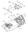
- the container 10 has a safety locking mechanism according to the invention, which is arranged on an underside of a bottom 26 of the housing 12.
- the safety lock mechanism has a mass in the form of a weight 28 and a spring element 30 bent from a spring wire.
- the weight 28 and the Spring element 30 are shown in Figure 2 as individual parts, wherein Figure 2 shows the weight 28 and the spring element 30 from the other side as Figure 1.
- the weight 28 has a journal 32 at a side edge which is received in a bearing hole in the bottom 26 of the housing 12. In this way, the weight 28 is pivotally mounted about the bearing pin 32 on the bottom 26 of the housing 12. This pivotal mounting of the weight 28 forms a guide with which the weight 28 is guided in an arcuate path about the bearing pin 32 and with respect to the housing 12 in approximately forward and backward movable.
- the weight 28 On a side opposite the bearing journal 32, the weight 28 has a snap-action pin 34, which cooperates with the spring element 30: the spring element 30 has a curvature 36 in its center, in which the snap-action pin 34 rests.
- the spring element 30 forms with its curvature 36 and the snap pin 34 of the weight 28 a snap device 28, 30, 34, 38, which holds the weight 28 in a basic position. If the weight 28 acts on a force of sufficient magnitude directed forwards or backwards with respect to the housing 12, then the snap-action pin 34 is released from the curvature 36 and the weight 28 can pivot forwards or backwards.
- the spring element 30 In a position inserted into the housing 12, the spring element 30 is curved elastically arcuate, while it is in the relaxed state (Figure 2) is substantially straight.
- the spring element 30 has a trapezoidal or dovetail-shaped bend 38, in the middle of the curvature 36 is located. Pages of the trapezoidal or dovetailed bend 38 form undercuts where the snap pin 34 can snap. If the weight 28 swings forwards or backwards, its snap-in pin 34 reaches one of the two sides of the trapezoidal or dovetail-shaped bend 38 of the spring element 30 and is held snapped there. The weight 28 can not swing back so.
- the spring element 30 with its trapezoidal or dovetail-shaped bend 38 and the weight 28 with the snap-action pin 34 thus form a further snap-action device 28, 30, 34, 38, which holds the weight 28 snapped into the forward or backward tilted, ie deflected, position , A swinging back of the weight 28 in its normal position is not provided.
- the weight 28 to its normal position would have the spring element 30 are bent to the side, including the on the underside of the bottom 26 of the housing 12 arranged spring element 30 be accessible or, for example, would have to be made by removing the container 10 from the dashboard, not shown.
- the highest occurring in normal driving accelerations and decelerations are not sufficient to snap the snap pin 34 of the mass 28 from the curvature 36 of the spring element 30.
- the weight 28 has two arms 40 which extend in one piece from the weight 28 in extension of the side of the weight 28 on which the bearing pin 32 is provided.
- the arms 40 have cranks 42 at their free ends. If the weight 28 is deflected, i. pivoted to or from the rear, the crank 42 of an arm 40 engages through a recess 44 of the insert 14. The insert 14 is thereby locked in its inserted into the housing 12, the closed position.
- the function of the safety lock mechanism 24 is as follows: if a front or rear acceleration or deceleration is applied to the weight 28 by a front or rear impact of a motor vehicle in which the container 10 is installed, the snap pin 34 of the weight 28 snaps the curvature 36 of the spring element 30, the weight 28 is pivoted and locked with the crank 42 of his one arm 40, the insert 14 in the housing 12. At the same time, the snap pin 34 snaps on one side of the trapezoidal or dovetailed bend 38 of the spring element 30, so that the weight 28 pivots, ie remains deflected, even if the acceleration or deceleration subsides or acts in the opposite direction. The insert 14 thereby remains locked during and after an accident in the closed position in the housing 12.
- FIG. 3 shows one of the two deflected positions of the weight 28.
Landscapes
- Engineering & Computer Science (AREA)
- Mechanical Engineering (AREA)
- Lock And Its Accessories (AREA)
- Vehicle Step Arrangements And Article Storage (AREA)
Claims (4)
- Mécanisme de verrouillage de sûreté pour un récipient dans un véhicule, comprenant une masse guidée avec mobilité, par un guide, d'une position initiale à une position sortie par pivotement, la masse maintenant le récipient fermé à l'état d'utilisation, lorsque ladite masse est déplacée jusqu'à la position sortie par pivotement ; et un système maintenant la masse dans la position initiale lorsqu'aucune accélération ou aucun ralentissement n'agit sur ladite masse dans une direction d'excursion pivotante, caractérisé par le fait que ledit mécanisme de verrouillage de sûreté (24) comporte un système à déclic (28, 30, 34, 38) qui maintient la masse (28) dans la position sortie par pivotement.
- Mécanisme de verrouillage de sûreté selon la revendication 1, caractérisé par le fait que la masse (28) peut être déviée dans deux directions opposées, est maintenue dans chaque position d'excursion pivotante par un système à déclic (28, 30, 34, 38), et maintient le récipient (10) fermé dans chaque position d'excursion pivotante.
- Mécanisme de verrouillage de sûreté selon la revendication 1, caractérisé par le fait que le système (28, 30, 34, 38), maintenant la masse (28) dans la position initiale, maintient ladite masse (28) dans ladite position initiale aussi longtemps qu'une accélération ou un ralentissement, agissant sur ladite masse (28) dans une direction d'excursion pivotante, n'excède pas une valeur de seuil.
- Mécanisme de verrouillage de sûreté selon la revendication 1, caractérisé par le fait que ledit mécanisme de verrouillage de sûreté (24) présente un élément élastique (30) qui matérialise le système (28, 30, 34, 38) retenant la masse (28) dans la position initiale, et le système à déclic (28, 30, 34, 38) retenant ladite masse (28) dans la position sortie par pivotement.
Applications Claiming Priority (3)
| Application Number | Priority Date | Filing Date | Title |
|---|---|---|---|
| DE2002124862 DE10224862A1 (de) | 2002-06-05 | 2002-06-05 | Sicherheitsverriegelungsvorrichtung für ein Behältnis in einem Fahrzeug |
| DE10224862 | 2002-06-05 | ||
| PCT/EP2003/005656 WO2003104591A1 (fr) | 2002-06-05 | 2003-05-30 | Dispositif de blocage securise pour recipient dans un vehicule |
Publications (2)
| Publication Number | Publication Date |
|---|---|
| EP1509663A1 EP1509663A1 (fr) | 2005-03-02 |
| EP1509663B1 true EP1509663B1 (fr) | 2007-01-10 |
Family
ID=29594272
Family Applications (1)
| Application Number | Title | Priority Date | Filing Date |
|---|---|---|---|
| EP03735497A Expired - Lifetime EP1509663B1 (fr) | 2002-06-05 | 2003-05-30 | Dispositif de blocage securise pour recipient dans un vehicule |
Country Status (4)
| Country | Link |
|---|---|
| US (1) | US7156427B2 (fr) |
| EP (1) | EP1509663B1 (fr) |
| DE (2) | DE10224862A1 (fr) |
| WO (1) | WO2003104591A1 (fr) |
Cited By (1)
| Publication number | Priority date | Publication date | Assignee | Title |
|---|---|---|---|---|
| DE102010060953A1 (de) | 2010-12-02 | 2012-06-06 | Fischer Automotive Systems Gmbh & Co. Kg | Sicherheitsverriegelungsvorrichtung für ein Behältnis in einem Fahrzeug |
Families Citing this family (9)
| Publication number | Priority date | Publication date | Assignee | Title |
|---|---|---|---|---|
| DE10340673A1 (de) | 2003-09-04 | 2005-03-31 | Fischer Automotive Systems Gmbh | Sicherheitsverriegelungsvorrichtung für ein Behältnis in einem Fahrzeug |
| ITRM20040337A1 (it) * | 2004-07-07 | 2004-10-07 | Valeo Sicurezza Abitacolo Spa | Maniglia di portiera, in particolare di autoveicolo, con sistema di sicurezza inerziale. |
| US7793995B2 (en) * | 2006-07-27 | 2010-09-14 | Illinois Tool Works Inc. | Push/push latch |
| DE102006049333A1 (de) * | 2006-10-19 | 2008-04-30 | Fischer Automotive Systems Gmbh | Unfallverriegelungseinrichtung |
| WO2009005786A1 (fr) * | 2007-06-29 | 2009-01-08 | Bbi Enterprises Group, Inc. | Ensemble garniture pour un véhicule |
| FR2958218B1 (fr) * | 2010-03-31 | 2012-05-04 | Faurecia Interieur Ind | Dispositif destine a equiper l'interieur d'un vehicule automobile, avec un mecanisme de commande de type "push-push |
| DE202010006291U1 (de) * | 2010-04-30 | 2011-09-23 | Minda Ktsn Plastic Solutions Gmbh & Co.Kg | Verriegelungseinrichtung |
| JP2019018415A (ja) * | 2017-07-13 | 2019-02-07 | キヤノン株式会社 | 記録装置及びその記録制御方法 |
| CN119160092B (zh) * | 2024-06-30 | 2025-09-26 | 岚图汽车科技有限公司 | 一种车载抽屉结构及汽车 |
Family Cites Families (11)
| Publication number | Priority date | Publication date | Assignee | Title |
|---|---|---|---|---|
| JPS606650U (ja) * | 1983-06-22 | 1985-01-18 | 本田技研工業株式会社 | 車両のインストルメントパネルに設けられる小物収納ボツクス |
| US4973014A (en) * | 1988-06-27 | 1990-11-27 | Creative Systems Engineering, Inc. | Conduit bracket lock system |
| JPH077225Y2 (ja) * | 1989-10-18 | 1995-02-22 | 株式会社ニフコ | 車載移動体の閉位置係止装置 |
| US5312143A (en) * | 1992-11-19 | 1994-05-17 | Buckner Almar W | Earthquake safety cabinet latch |
| DE69400926T2 (de) * | 1993-02-12 | 1997-06-12 | Kato Hatsujo Kaisha Ltd | Bewahrungsvorrichtung mit einer Sicherheitsfunktion |
| US5292159A (en) * | 1993-03-24 | 1994-03-08 | Nyx, Inc. | Latch mechanism for vehicle glove boxes or the like |
| DE9412661U1 (de) * | 1994-08-05 | 1994-10-06 | Sidler GmbH & Co, 72072 Tübingen | Verriegelungsvorrichtung |
| US5597188A (en) * | 1995-06-19 | 1997-01-28 | Miche; John A. | Earthquake latch |
| DE10120435A1 (de) * | 2001-04-26 | 2002-10-31 | Fischer Artur Werke Gmbh | Push-Push-Verriegelungsmechanik |
| DE10121681A1 (de) * | 2001-05-04 | 2002-11-07 | Volkswagen Ag | Verschlußeinrichtung für ein Gehäuse bei einem Fahrzeug |
| EP1396596B1 (fr) * | 2002-09-06 | 2009-12-09 | Hawa Ag | Dispositif de verrouillage pour élément de séparation |
-
2002
- 2002-06-05 DE DE2002124862 patent/DE10224862A1/de not_active Withdrawn
-
2003
- 2003-05-30 DE DE50306261T patent/DE50306261D1/de not_active Expired - Lifetime
- 2003-05-30 US US10/516,048 patent/US7156427B2/en not_active Expired - Lifetime
- 2003-05-30 WO PCT/EP2003/005656 patent/WO2003104591A1/fr not_active Ceased
- 2003-05-30 EP EP03735497A patent/EP1509663B1/fr not_active Expired - Lifetime
Cited By (2)
| Publication number | Priority date | Publication date | Assignee | Title |
|---|---|---|---|---|
| DE102010060953A1 (de) | 2010-12-02 | 2012-06-06 | Fischer Automotive Systems Gmbh & Co. Kg | Sicherheitsverriegelungsvorrichtung für ein Behältnis in einem Fahrzeug |
| WO2012072206A1 (fr) | 2010-12-02 | 2012-06-07 | Fischer Automotive Systems Gmbh & Co. Kg | Dispositif de verrouillage de sécurité pour un récipient, dans un véhicule |
Also Published As
| Publication number | Publication date |
|---|---|
| US7156427B2 (en) | 2007-01-02 |
| DE50306261D1 (de) | 2007-02-22 |
| US20050173931A1 (en) | 2005-08-11 |
| EP1509663A1 (fr) | 2005-03-02 |
| WO2003104591A1 (fr) | 2003-12-18 |
| DE10224862A1 (de) | 2003-12-24 |
Similar Documents
| Publication | Publication Date | Title |
|---|---|---|
| EP1926633B1 (fr) | Compartiment de rangement pour un vehicule automobile | |
| DE60000528T2 (de) | Fahrzeugbremspedalanordnung | |
| DE19835364C2 (de) | Vorrichtung zum Einbau in einem Kraftwagen mit einem Ausziehteil | |
| EP2171189B1 (fr) | Système de verrouillage pour le capot avant d'un véhicule automobile | |
| EP1509663B1 (fr) | Dispositif de blocage securise pour recipient dans un vehicule | |
| DE102010050800A1 (de) | Verriegelungseinrichtung mit einer Push-Push-Mechanik für einen zwischen einer Schließ- und Offenstellung betätigbaren Behälter oder Deckel, insbesondere von Kraftfahrzeugen | |
| DE102004003165A1 (de) | Arretierungsmechanismus und Vorrichtung zum Öffnen und Schließen | |
| EP1660743B1 (fr) | Dispositif de verrouillage de securite destine a un contenant dans un vehicule | |
| DE102011053395A1 (de) | Mittelkonsolenanordnung | |
| DE10027020A1 (de) | Mittelkonsole für Fahrzeuge | |
| DE20215067U1 (de) | Antrieb zur Realisierung einer Schwenk-Kippbewegung für ein Bauteil, insbesondere im Innenraum von Fahrzeugen | |
| DE10009291B4 (de) | Armlehne mit Staufach und verriegelbarem Deckel | |
| EP2534326B1 (fr) | Dispositif d'escamotage pour portes coulissants | |
| DE102008000098A1 (de) | Türaußengriffanordnung für Fahrzeuge | |
| DE102006014822B4 (de) | Raumausstattungsteil für Fahrzeuge | |
| EP2798137A1 (fr) | Dispositif de blocage de déverrouillage, compartiment de stockage pourvu d'un dispositif de blocage de déverrouillage, et procédé de blocage d'un déverrouillage d'un compartiment de stockage activé par accélération | |
| DE102005027379B4 (de) | Verriegelungseinrichtung für einen Deckel an einem Ablagefach in einem Kraftfahrzeug | |
| EP2072717A1 (fr) | Unité de poignée à palette, en particulier pour un compartiment de dépôt/coffre de rangement d'un véhicule automobile | |
| DE102010023731A1 (de) | Sperreinrichtung für ein in einer Fahrzeugtüre eines Kraftfahrzeugs schwenkbar angeordneten Bauteils | |
| EP3990727B1 (fr) | Dispositif de verrouillage destiné à un récipient ou un couvercle, en particulier de véhicules automobiles, et pouvant être actionné entre une position fermée et une position ouverte | |
| EP1582403B1 (fr) | Dispositif de maintien pour récipient de nourriture ou boisson | |
| DE102017123410B4 (de) | Axiale crash-sperreinrichtung | |
| DE102018107239B4 (de) | Ablagefach für ein kraftfahrzeug | |
| DE10022436A1 (de) | Dämpfungseinrichtung | |
| DE19911589C5 (de) | Fahrzeugsitz, insbesondere Kraftfahrzeugsitz, mit einer Betätigungseinrichtung |
Legal Events
| Date | Code | Title | Description |
|---|---|---|---|
| PUAI | Public reference made under article 153(3) epc to a published international application that has entered the european phase |
Free format text: ORIGINAL CODE: 0009012 |
|
| 17P | Request for examination filed |
Effective date: 20041112 |
|
| AK | Designated contracting states |
Kind code of ref document: A1 Designated state(s): AT BE BG CH CY CZ DE DK EE ES FI FR GB GR HU IE IT LI LU MC NL PT RO SE SI SK TR |
|
| GRAP | Despatch of communication of intention to grant a patent |
Free format text: ORIGINAL CODE: EPIDOSNIGR1 |
|
| GRAS | Grant fee paid |
Free format text: ORIGINAL CODE: EPIDOSNIGR3 |
|
| GRAA | (expected) grant |
Free format text: ORIGINAL CODE: 0009210 |
|
| AK | Designated contracting states |
Kind code of ref document: B1 Designated state(s): AT BE BG CH CY CZ DE DK EE ES FI FR GB GR HU IE IT LI LU MC NL PT RO SE SI SK TR |
|
| PG25 | Lapsed in a contracting state [announced via postgrant information from national office to epo] |
Ref country code: SI Free format text: LAPSE BECAUSE OF FAILURE TO SUBMIT A TRANSLATION OF THE DESCRIPTION OR TO PAY THE FEE WITHIN THE PRESCRIBED TIME-LIMIT Effective date: 20070110 Ref country code: FI Free format text: LAPSE BECAUSE OF FAILURE TO SUBMIT A TRANSLATION OF THE DESCRIPTION OR TO PAY THE FEE WITHIN THE PRESCRIBED TIME-LIMIT Effective date: 20070110 Ref country code: NL Free format text: LAPSE BECAUSE OF FAILURE TO SUBMIT A TRANSLATION OF THE DESCRIPTION OR TO PAY THE FEE WITHIN THE PRESCRIBED TIME-LIMIT Effective date: 20070110 Ref country code: IE Free format text: LAPSE BECAUSE OF FAILURE TO SUBMIT A TRANSLATION OF THE DESCRIPTION OR TO PAY THE FEE WITHIN THE PRESCRIBED TIME-LIMIT Effective date: 20070110 Ref country code: DK Free format text: LAPSE BECAUSE OF FAILURE TO SUBMIT A TRANSLATION OF THE DESCRIPTION OR TO PAY THE FEE WITHIN THE PRESCRIBED TIME-LIMIT Effective date: 20070110 |
|
| REG | Reference to a national code |
Ref country code: GB Ref legal event code: FG4D Free format text: NOT ENGLISH |
|
| REG | Reference to a national code |
Ref country code: IE Ref legal event code: FG4D Free format text: LANGUAGE OF EP DOCUMENT: GERMAN |
|
| REF | Corresponds to: |
Ref document number: 50306261 Country of ref document: DE Date of ref document: 20070222 Kind code of ref document: P |
|
| PG25 | Lapsed in a contracting state [announced via postgrant information from national office to epo] |
Ref country code: SE Free format text: LAPSE BECAUSE OF FAILURE TO SUBMIT A TRANSLATION OF THE DESCRIPTION OR TO PAY THE FEE WITHIN THE PRESCRIBED TIME-LIMIT Effective date: 20070410 |
|
| PG25 | Lapsed in a contracting state [announced via postgrant information from national office to epo] |
Ref country code: BG Free format text: LAPSE BECAUSE OF EXPIRATION OF PROTECTION Effective date: 20070411 |
|
| PG25 | Lapsed in a contracting state [announced via postgrant information from national office to epo] |
Ref country code: ES Free format text: LAPSE BECAUSE OF FAILURE TO SUBMIT A TRANSLATION OF THE DESCRIPTION OR TO PAY THE FEE WITHIN THE PRESCRIBED TIME-LIMIT Effective date: 20070421 |
|
| GBT | Gb: translation of ep patent filed (gb section 77(6)(a)/1977) |
Effective date: 20070412 |
|
| PG25 | Lapsed in a contracting state [announced via postgrant information from national office to epo] |
Ref country code: PT Free format text: LAPSE BECAUSE OF FAILURE TO SUBMIT A TRANSLATION OF THE DESCRIPTION OR TO PAY THE FEE WITHIN THE PRESCRIBED TIME-LIMIT Effective date: 20070611 |
|
| ET | Fr: translation filed | ||
| NLV1 | Nl: lapsed or annulled due to failure to fulfill the requirements of art. 29p and 29m of the patents act | ||
| REG | Reference to a national code |
Ref country code: IE Ref legal event code: FD4D |
|
| PLBE | No opposition filed within time limit |
Free format text: ORIGINAL CODE: 0009261 |
|
| STAA | Information on the status of an ep patent application or granted ep patent |
Free format text: STATUS: NO OPPOSITION FILED WITHIN TIME LIMIT |
|
| PG25 | Lapsed in a contracting state [announced via postgrant information from national office to epo] |
Ref country code: SK Free format text: LAPSE BECAUSE OF FAILURE TO SUBMIT A TRANSLATION OF THE DESCRIPTION OR TO PAY THE FEE WITHIN THE PRESCRIBED TIME-LIMIT Effective date: 20070110 |
|
| 26N | No opposition filed |
Effective date: 20071011 |
|
| BERE | Be: lapsed |
Owner name: FISCHER AUTOMOTIVE SYSTEMS G.M.B.H. Effective date: 20070531 |
|
| PG25 | Lapsed in a contracting state [announced via postgrant information from national office to epo] |
Ref country code: RO Free format text: LAPSE BECAUSE OF FAILURE TO SUBMIT A TRANSLATION OF THE DESCRIPTION OR TO PAY THE FEE WITHIN THE PRESCRIBED TIME-LIMIT Effective date: 20070110 |
|
| REG | Reference to a national code |
Ref country code: CH Ref legal event code: PL |
|
| PG25 | Lapsed in a contracting state [announced via postgrant information from national office to epo] |
Ref country code: MC Free format text: LAPSE BECAUSE OF NON-PAYMENT OF DUE FEES Effective date: 20070531 |
|
| PG25 | Lapsed in a contracting state [announced via postgrant information from national office to epo] |
Ref country code: CH Free format text: LAPSE BECAUSE OF NON-PAYMENT OF DUE FEES Effective date: 20070531 Ref country code: LI Free format text: LAPSE BECAUSE OF NON-PAYMENT OF DUE FEES Effective date: 20070531 |
|
| PG25 | Lapsed in a contracting state [announced via postgrant information from national office to epo] |
Ref country code: BE Free format text: LAPSE BECAUSE OF NON-PAYMENT OF DUE FEES Effective date: 20070531 |
|
| PG25 | Lapsed in a contracting state [announced via postgrant information from national office to epo] |
Ref country code: GR Free format text: LAPSE BECAUSE OF FAILURE TO SUBMIT A TRANSLATION OF THE DESCRIPTION OR TO PAY THE FEE WITHIN THE PRESCRIBED TIME-LIMIT Effective date: 20070411 |
|
| PGFP | Annual fee paid to national office [announced via postgrant information from national office to epo] |
Ref country code: CZ Payment date: 20080526 Year of fee payment: 6 |
|
| PG25 | Lapsed in a contracting state [announced via postgrant information from national office to epo] |
Ref country code: AT Free format text: LAPSE BECAUSE OF NON-PAYMENT OF DUE FEES Effective date: 20070530 |
|
| PGFP | Annual fee paid to national office [announced via postgrant information from national office to epo] |
Ref country code: IT Payment date: 20080522 Year of fee payment: 6 |
|
| PG25 | Lapsed in a contracting state [announced via postgrant information from national office to epo] |
Ref country code: EE Free format text: LAPSE BECAUSE OF FAILURE TO SUBMIT A TRANSLATION OF THE DESCRIPTION OR TO PAY THE FEE WITHIN THE PRESCRIBED TIME-LIMIT Effective date: 20070110 |
|
| PG25 | Lapsed in a contracting state [announced via postgrant information from national office to epo] |
Ref country code: CY Free format text: LAPSE BECAUSE OF FAILURE TO SUBMIT A TRANSLATION OF THE DESCRIPTION OR TO PAY THE FEE WITHIN THE PRESCRIBED TIME-LIMIT Effective date: 20070110 |
|
| PG25 | Lapsed in a contracting state [announced via postgrant information from national office to epo] |
Ref country code: LU Free format text: LAPSE BECAUSE OF NON-PAYMENT OF DUE FEES Effective date: 20070530 |
|
| PG25 | Lapsed in a contracting state [announced via postgrant information from national office to epo] |
Ref country code: HU Free format text: LAPSE BECAUSE OF FAILURE TO SUBMIT A TRANSLATION OF THE DESCRIPTION OR TO PAY THE FEE WITHIN THE PRESCRIBED TIME-LIMIT Effective date: 20070711 Ref country code: TR Free format text: LAPSE BECAUSE OF FAILURE TO SUBMIT A TRANSLATION OF THE DESCRIPTION OR TO PAY THE FEE WITHIN THE PRESCRIBED TIME-LIMIT Effective date: 20070110 |
|
| PG25 | Lapsed in a contracting state [announced via postgrant information from national office to epo] |
Ref country code: CZ Free format text: LAPSE BECAUSE OF NON-PAYMENT OF DUE FEES Effective date: 20090530 |
|
| REG | Reference to a national code |
Ref country code: FR Ref legal event code: ST Effective date: 20100129 |
|
| PG25 | Lapsed in a contracting state [announced via postgrant information from national office to epo] |
Ref country code: FR Free format text: LAPSE BECAUSE OF NON-PAYMENT OF DUE FEES Effective date: 20090602 |
|
| PGFP | Annual fee paid to national office [announced via postgrant information from national office to epo] |
Ref country code: FR Payment date: 20080526 Year of fee payment: 6 |
|
| PG25 | Lapsed in a contracting state [announced via postgrant information from national office to epo] |
Ref country code: IT Free format text: LAPSE BECAUSE OF NON-PAYMENT OF DUE FEES Effective date: 20090530 |
|
| PGFP | Annual fee paid to national office [announced via postgrant information from national office to epo] |
Ref country code: GB Payment date: 20110520 Year of fee payment: 9 |
|
| GBPC | Gb: european patent ceased through non-payment of renewal fee |
Effective date: 20120530 |
|
| PG25 | Lapsed in a contracting state [announced via postgrant information from national office to epo] |
Ref country code: GB Free format text: LAPSE BECAUSE OF NON-PAYMENT OF DUE FEES Effective date: 20120530 |
|
| PGFP | Annual fee paid to national office [announced via postgrant information from national office to epo] |
Ref country code: DE Payment date: 20210423 Year of fee payment: 19 |
|
| REG | Reference to a national code |
Ref country code: DE Ref legal event code: R119 Ref document number: 50306261 Country of ref document: DE |
|
| PG25 | Lapsed in a contracting state [announced via postgrant information from national office to epo] |
Ref country code: DE Free format text: LAPSE BECAUSE OF NON-PAYMENT OF DUE FEES Effective date: 20221201 |