EP1513207B1 - Brennstoffzellen-stromerzeugungssystem und verfahren zu seinem betrieb - Google Patents
Brennstoffzellen-stromerzeugungssystem und verfahren zu seinem betrieb Download PDFInfo
- Publication number
- EP1513207B1 EP1513207B1 EP03719202A EP03719202A EP1513207B1 EP 1513207 B1 EP1513207 B1 EP 1513207B1 EP 03719202 A EP03719202 A EP 03719202A EP 03719202 A EP03719202 A EP 03719202A EP 1513207 B1 EP1513207 B1 EP 1513207B1
- Authority
- EP
- European Patent Office
- Prior art keywords
- fuel
- gas
- oxygen
- fuel cell
- reforming device
- Prior art date
- Legal status (The legal status is an assumption and is not a legal conclusion. Google has not performed a legal analysis and makes no representation as to the accuracy of the status listed.)
- Expired - Lifetime
Links
- 239000000446 fuel Substances 0.000 title claims abstract description 306
- 238000010248 power generation Methods 0.000 title claims abstract description 113
- 238000000034 method Methods 0.000 title claims description 45
- 239000001301 oxygen Substances 0.000 claims abstract description 226
- 229910052760 oxygen Inorganic materials 0.000 claims abstract description 226
- QVGXLLKOCUKJST-UHFFFAOYSA-N atomic oxygen Chemical compound [O] QVGXLLKOCUKJST-UHFFFAOYSA-N 0.000 claims abstract description 225
- 239000007789 gas Substances 0.000 claims abstract description 202
- 238000002407 reforming Methods 0.000 claims abstract description 137
- 239000011261 inert gas Substances 0.000 claims abstract description 129
- 238000010438 heat treatment Methods 0.000 claims abstract description 12
- 239000003054 catalyst Substances 0.000 claims description 116
- 239000003463 adsorbent Substances 0.000 claims description 112
- 210000004027 cell Anatomy 0.000 claims description 98
- 238000010926 purge Methods 0.000 claims description 57
- 210000005056 cell body Anatomy 0.000 claims description 49
- 238000006243 chemical reaction Methods 0.000 claims description 47
- 239000010949 copper Substances 0.000 claims description 25
- 239000002737 fuel gas Substances 0.000 claims description 23
- 230000015572 biosynthetic process Effects 0.000 claims description 19
- 238000007254 oxidation reaction Methods 0.000 claims description 19
- 230000003647 oxidation Effects 0.000 claims description 16
- 230000002829 reductive effect Effects 0.000 claims description 12
- 230000008929 regeneration Effects 0.000 claims description 11
- 238000011069 regeneration method Methods 0.000 claims description 11
- PXHVJJICTQNCMI-UHFFFAOYSA-N Nickel Chemical compound [Ni] PXHVJJICTQNCMI-UHFFFAOYSA-N 0.000 claims description 10
- 239000011651 chromium Substances 0.000 claims description 7
- 229910052802 copper Inorganic materials 0.000 claims description 7
- 239000011572 manganese Substances 0.000 claims description 7
- 238000011144 upstream manufacturing Methods 0.000 claims description 7
- XEEYBQQBJWHFJM-UHFFFAOYSA-N Iron Chemical compound [Fe] XEEYBQQBJWHFJM-UHFFFAOYSA-N 0.000 claims description 6
- RYGMFSIKBFXOCR-UHFFFAOYSA-N Copper Chemical compound [Cu] RYGMFSIKBFXOCR-UHFFFAOYSA-N 0.000 claims description 4
- 229910052804 chromium Inorganic materials 0.000 claims description 4
- 229910052748 manganese Inorganic materials 0.000 claims description 4
- 229910052759 nickel Inorganic materials 0.000 claims description 4
- VYZAMTAEIAYCRO-UHFFFAOYSA-N Chromium Chemical compound [Cr] VYZAMTAEIAYCRO-UHFFFAOYSA-N 0.000 claims description 3
- PWHULOQIROXLJO-UHFFFAOYSA-N Manganese Chemical compound [Mn] PWHULOQIROXLJO-UHFFFAOYSA-N 0.000 claims description 3
- 229910017052 cobalt Inorganic materials 0.000 claims description 3
- 239000010941 cobalt Substances 0.000 claims description 3
- GUTLYIVDDKVIGB-UHFFFAOYSA-N cobalt atom Chemical compound [Co] GUTLYIVDDKVIGB-UHFFFAOYSA-N 0.000 claims description 3
- JBQYATWDVHIOAR-UHFFFAOYSA-N tellanylidenegermanium Chemical compound [Te]=[Ge] JBQYATWDVHIOAR-UHFFFAOYSA-N 0.000 claims description 2
- 239000006096 absorbing agent Substances 0.000 abstract description 3
- 239000000126 substance Substances 0.000 abstract description 2
- 230000001590 oxidative effect Effects 0.000 abstract 1
- CURLTUGMZLYLDI-UHFFFAOYSA-N Carbon dioxide Chemical compound O=C=O CURLTUGMZLYLDI-UHFFFAOYSA-N 0.000 description 84
- 239000000243 solution Substances 0.000 description 50
- 229910002092 carbon dioxide Inorganic materials 0.000 description 44
- 239000001569 carbon dioxide Substances 0.000 description 38
- 150000001412 amines Chemical class 0.000 description 32
- 238000001179 sorption measurement Methods 0.000 description 19
- 238000006722 reduction reaction Methods 0.000 description 18
- 238000012360 testing method Methods 0.000 description 15
- 230000003247 decreasing effect Effects 0.000 description 12
- 230000000694 effects Effects 0.000 description 11
- GEHJYWRUCIMESM-UHFFFAOYSA-L sodium sulfite Chemical compound [Na+].[Na+].[O-]S([O-])=O GEHJYWRUCIMESM-UHFFFAOYSA-L 0.000 description 11
- 239000011701 zinc Substances 0.000 description 10
- 239000000203 mixture Substances 0.000 description 8
- IJGRMHOSHXDMSA-UHFFFAOYSA-N Atomic nitrogen Chemical compound N#N IJGRMHOSHXDMSA-UHFFFAOYSA-N 0.000 description 7
- 238000010521 absorption reaction Methods 0.000 description 6
- 238000002485 combustion reaction Methods 0.000 description 6
- UFHFLCQGNIYNRP-UHFFFAOYSA-N Hydrogen Chemical compound [H][H] UFHFLCQGNIYNRP-UHFFFAOYSA-N 0.000 description 5
- 238000005516 engineering process Methods 0.000 description 5
- 238000011084 recovery Methods 0.000 description 5
- XLYOFNOQVPJJNP-UHFFFAOYSA-N water Substances O XLYOFNOQVPJJNP-UHFFFAOYSA-N 0.000 description 5
- 238000006477 desulfuration reaction Methods 0.000 description 4
- 230000023556 desulfurization Effects 0.000 description 4
- 239000001257 hydrogen Substances 0.000 description 4
- 229910052739 hydrogen Inorganic materials 0.000 description 4
- 238000007689 inspection Methods 0.000 description 4
- 238000009434 installation Methods 0.000 description 4
- 238000012423 maintenance Methods 0.000 description 4
- VNWKTOKETHGBQD-UHFFFAOYSA-N methane Chemical compound C VNWKTOKETHGBQD-UHFFFAOYSA-N 0.000 description 4
- 229940001482 sodium sulfite Drugs 0.000 description 4
- 235000010265 sodium sulphite Nutrition 0.000 description 4
- 239000012808 vapor phase Substances 0.000 description 4
- UGFAIRIUMAVXCW-UHFFFAOYSA-N Carbon monoxide Chemical compound [O+]#[C-] UGFAIRIUMAVXCW-UHFFFAOYSA-N 0.000 description 3
- MYMOFIZGZYHOMD-UHFFFAOYSA-N Dioxygen Chemical compound O=O MYMOFIZGZYHOMD-UHFFFAOYSA-N 0.000 description 3
- ATUOYWHBWRKTHZ-UHFFFAOYSA-N Propane Chemical compound CCC ATUOYWHBWRKTHZ-UHFFFAOYSA-N 0.000 description 3
- 229910002091 carbon monoxide Inorganic materials 0.000 description 3
- 239000003638 chemical reducing agent Substances 0.000 description 3
- 238000001816 cooling Methods 0.000 description 3
- 230000006866 deterioration Effects 0.000 description 3
- 229910001882 dioxygen Inorganic materials 0.000 description 3
- 229910052757 nitrogen Inorganic materials 0.000 description 3
- 239000007800 oxidant agent Substances 0.000 description 3
- 239000010970 precious metal Substances 0.000 description 3
- 230000001105 regulatory effect Effects 0.000 description 3
- 229920006395 saturated elastomer Polymers 0.000 description 3
- 238000000629 steam reforming Methods 0.000 description 3
- DKGAVHZHDRPRBM-UHFFFAOYSA-N Tert-Butanol Chemical compound CC(C)(C)O DKGAVHZHDRPRBM-UHFFFAOYSA-N 0.000 description 2
- 229910021536 Zeolite Inorganic materials 0.000 description 2
- 230000002411 adverse Effects 0.000 description 2
- PNEYBMLMFCGWSK-UHFFFAOYSA-N aluminium oxide Inorganic materials [O-2].[O-2].[O-2].[Al+3].[Al+3] PNEYBMLMFCGWSK-UHFFFAOYSA-N 0.000 description 2
- 239000007864 aqueous solution Substances 0.000 description 2
- 235000011089 carbon dioxide Nutrition 0.000 description 2
- 229910052593 corundum Inorganic materials 0.000 description 2
- QDOXWKRWXJOMAK-UHFFFAOYSA-N dichromium trioxide Chemical compound O=[Cr]O[Cr]=O QDOXWKRWXJOMAK-UHFFFAOYSA-N 0.000 description 2
- HNPSIPDUKPIQMN-UHFFFAOYSA-N dioxosilane;oxo(oxoalumanyloxy)alumane Chemical compound O=[Si]=O.O=[Al]O[Al]=O HNPSIPDUKPIQMN-UHFFFAOYSA-N 0.000 description 2
- 238000003487 electrochemical reaction Methods 0.000 description 2
- 229910052742 iron Inorganic materials 0.000 description 2
- 150000003141 primary amines Chemical class 0.000 description 2
- 239000002994 raw material Substances 0.000 description 2
- 238000004064 recycling Methods 0.000 description 2
- 239000007858 starting material Substances 0.000 description 2
- 238000003860 storage Methods 0.000 description 2
- 229910001845 yogo sapphire Inorganic materials 0.000 description 2
- 239000010457 zeolite Substances 0.000 description 2
- 229910052725 zinc Inorganic materials 0.000 description 2
- 239000007832 Na2SO4 Substances 0.000 description 1
- VYPSYNLAJGMNEJ-UHFFFAOYSA-N Silicium dioxide Chemical compound O=[Si]=O VYPSYNLAJGMNEJ-UHFFFAOYSA-N 0.000 description 1
- PMZURENOXWZQFD-UHFFFAOYSA-L Sodium Sulfate Chemical compound [Na+].[Na+].[O-]S([O-])(=O)=O PMZURENOXWZQFD-UHFFFAOYSA-L 0.000 description 1
- HCHKCACWOHOZIP-UHFFFAOYSA-N Zinc Chemical compound [Zn] HCHKCACWOHOZIP-UHFFFAOYSA-N 0.000 description 1
- 230000005856 abnormality Effects 0.000 description 1
- 230000009286 beneficial effect Effects 0.000 description 1
- 230000003197 catalytic effect Effects 0.000 description 1
- 238000004891 communication Methods 0.000 description 1
- 230000007423 decrease Effects 0.000 description 1
- 230000001419 dependent effect Effects 0.000 description 1
- 230000002542 deteriorative effect Effects 0.000 description 1
- 230000005611 electricity Effects 0.000 description 1
- 150000002431 hydrogen Chemical class 0.000 description 1
- 238000009413 insulation Methods 0.000 description 1
- 239000012212 insulator Substances 0.000 description 1
- JEIPFZHSYJVQDO-UHFFFAOYSA-N iron(III) oxide Inorganic materials O=[Fe]O[Fe]=O JEIPFZHSYJVQDO-UHFFFAOYSA-N 0.000 description 1
- 238000005304 joining Methods 0.000 description 1
- 239000003350 kerosene Substances 0.000 description 1
- 239000007788 liquid Substances 0.000 description 1
- 238000004519 manufacturing process Methods 0.000 description 1
- 238000002156 mixing Methods 0.000 description 1
- 239000002808 molecular sieve Substances 0.000 description 1
- JCXJVPUVTGWSNB-UHFFFAOYSA-N nitrogen dioxide Inorganic materials O=[N]=O JCXJVPUVTGWSNB-UHFFFAOYSA-N 0.000 description 1
- 239000008188 pellet Substances 0.000 description 1
- 230000002265 prevention Effects 0.000 description 1
- 239000001294 propane Substances 0.000 description 1
- 238000006479 redox reaction Methods 0.000 description 1
- 230000000717 retained effect Effects 0.000 description 1
- 239000000741 silica gel Substances 0.000 description 1
- 229910002027 silica gel Inorganic materials 0.000 description 1
- URGAHOPLAPQHLN-UHFFFAOYSA-N sodium aluminosilicate Chemical compound [Na+].[Al+3].[O-][Si]([O-])=O.[O-][Si]([O-])=O URGAHOPLAPQHLN-UHFFFAOYSA-N 0.000 description 1
- 229910052938 sodium sulfate Inorganic materials 0.000 description 1
- 230000002269 spontaneous effect Effects 0.000 description 1
- 231100000167 toxic agent Toxicity 0.000 description 1
- 239000003440 toxic substance Substances 0.000 description 1
Images



Classifications
-
- C—CHEMISTRY; METALLURGY
- C01—INORGANIC CHEMISTRY
- C01B—NON-METALLIC ELEMENTS; COMPOUNDS THEREOF; METALLOIDS OR COMPOUNDS THEREOF NOT COVERED BY SUBCLASS C01C
- C01B13/00—Oxygen; Ozone; Oxides or hydroxides in general
- C01B13/02—Preparation of oxygen
- C01B13/0229—Purification or separation processes
- C01B13/0248—Physical processing only
- C01B13/0259—Physical processing only by adsorption on solids
- C01B13/0262—Physical processing only by adsorption on solids characterised by the adsorbent
-
- H—ELECTRICITY
- H01—ELECTRIC ELEMENTS
- H01M—PROCESSES OR MEANS, e.g. BATTERIES, FOR THE DIRECT CONVERSION OF CHEMICAL ENERGY INTO ELECTRICAL ENERGY
- H01M8/00—Fuel cells; Manufacture thereof
- H01M8/04—Auxiliary arrangements, e.g. for control of pressure or for circulation of fluids
- H01M8/04223—Auxiliary arrangements, e.g. for control of pressure or for circulation of fluids during start-up or shut-down; Depolarisation or activation, e.g. purging; Means for short-circuiting defective fuel cells
- H01M8/04231—Purging of the reactants
-
- H—ELECTRICITY
- H01—ELECTRIC ELEMENTS
- H01M—PROCESSES OR MEANS, e.g. BATTERIES, FOR THE DIRECT CONVERSION OF CHEMICAL ENERGY INTO ELECTRICAL ENERGY
- H01M8/00—Fuel cells; Manufacture thereof
- H01M8/06—Combination of fuel cells with means for production of reactants or for treatment of residues
- H01M8/0606—Combination of fuel cells with means for production of reactants or for treatment of residues with means for production of gaseous reactants
- H01M8/0612—Combination of fuel cells with means for production of reactants or for treatment of residues with means for production of gaseous reactants from carbon-containing material
-
- B—PERFORMING OPERATIONS; TRANSPORTING
- B01—PHYSICAL OR CHEMICAL PROCESSES OR APPARATUS IN GENERAL
- B01D—SEPARATION
- B01D2257/00—Components to be removed
- B01D2257/10—Single element gases other than halogens
- B01D2257/104—Oxygen
-
- B—PERFORMING OPERATIONS; TRANSPORTING
- B01—PHYSICAL OR CHEMICAL PROCESSES OR APPARATUS IN GENERAL
- B01D—SEPARATION
- B01D2258/00—Sources of waste gases
- B01D2258/02—Other waste gases
- B01D2258/0208—Other waste gases from fuel cells
-
- B—PERFORMING OPERATIONS; TRANSPORTING
- B01—PHYSICAL OR CHEMICAL PROCESSES OR APPARATUS IN GENERAL
- B01D—SEPARATION
- B01D53/00—Separation of gases or vapours; Recovering vapours of volatile solvents from gases; Chemical or biological purification of waste gases, e.g. engine exhaust gases, smoke, fumes, flue gases, aerosols
- B01D53/02—Separation of gases or vapours; Recovering vapours of volatile solvents from gases; Chemical or biological purification of waste gases, e.g. engine exhaust gases, smoke, fumes, flue gases, aerosols by adsorption, e.g. preparative gas chromatography
- B01D53/04—Separation of gases or vapours; Recovering vapours of volatile solvents from gases; Chemical or biological purification of waste gases, e.g. engine exhaust gases, smoke, fumes, flue gases, aerosols by adsorption, e.g. preparative gas chromatography with stationary adsorbents
- B01D53/0407—Constructional details of adsorbing systems
-
- C—CHEMISTRY; METALLURGY
- C01—INORGANIC CHEMISTRY
- C01B—NON-METALLIC ELEMENTS; COMPOUNDS THEREOF; METALLOIDS OR COMPOUNDS THEREOF NOT COVERED BY SUBCLASS C01C
- C01B2203/00—Integrated processes for the production of hydrogen or synthesis gas
- C01B2203/06—Integration with other chemical processes
- C01B2203/066—Integration with other chemical processes with fuel cells
-
- C—CHEMISTRY; METALLURGY
- C01—INORGANIC CHEMISTRY
- C01B—NON-METALLIC ELEMENTS; COMPOUNDS THEREOF; METALLOIDS OR COMPOUNDS THEREOF NOT COVERED BY SUBCLASS C01C
- C01B2210/00—Purification or separation of specific gases
- C01B2210/0043—Impurity removed
- C01B2210/0046—Nitrogen
-
- Y—GENERAL TAGGING OF NEW TECHNOLOGICAL DEVELOPMENTS; GENERAL TAGGING OF CROSS-SECTIONAL TECHNOLOGIES SPANNING OVER SEVERAL SECTIONS OF THE IPC; TECHNICAL SUBJECTS COVERED BY FORMER USPC CROSS-REFERENCE ART COLLECTIONS [XRACs] AND DIGESTS
- Y02—TECHNOLOGIES OR APPLICATIONS FOR MITIGATION OR ADAPTATION AGAINST CLIMATE CHANGE
- Y02E—REDUCTION OF GREENHOUSE GAS [GHG] EMISSIONS, RELATED TO ENERGY GENERATION, TRANSMISSION OR DISTRIBUTION
- Y02E60/00—Enabling technologies; Technologies with a potential or indirect contribution to GHG emissions mitigation
- Y02E60/30—Hydrogen technology
- Y02E60/50—Fuel cells
Definitions
- This invention relates to a fuel cell power generation system and a method for operating it. More particularly, the invention relates to a technology which can reliably remove residual matter, such as a combustible gas ormoisture, oxygen, etc., without leaving them within a fuel reforming device, at a low cost and with a compact configuration.
- a fuel cell power generation system is mainly composed of a fuel reforming device and a fuel cell body, and has attracted attention as a dispersed type power source for households, etc..
- the fuel reforming device converts a fuel gas, such as city gas, into a hydrogen-rich reformed gas, and supplies it to the fuel cell body.
- the fuel cell body reacts the reformed gas with air electrochemically to generate electrical power.
- a combustible gas such as hydrogen or methane, moisture, and so on remain in different parts of the fuel reforming device or the like.
- the combustible gas may leak to the outside, or moisture may form dew on a catalyst, deteriorating the catalyst.
- Japanese Patent Application Laid-Open No. 2001-277137 proposes to feed air into the fuel reforming device at the time of stopping power generation to fill the fuel reforming device with air, thereby removing residual matter, such as a combustible gas or moisture, from the interior of the fuel reforming device.
- oxygen in the air is likely to deteriorate the catalyst of the fuel reforming device (especially, a Cu/Zn-based LTS catalyst used in a CO conversion reaction).
- Japanese Patent Application Laid-Open No. 2001-180908 proposes that a precious metal catalyst minimally deteriorated by oxygen be applied to the fuel reforming device.
- the precious metal catalyst is lower in catalytic efficiency than the Cu/Zn-based catalyst (about 1/5 to 1/10 expressed as volume ratio) , thus resulting in the upsizing of the fuel reforming device, and posing difficulty in heating the entire device uniformly.
- Japanese Patent Application Laid-Open No. 2000-277137 proposes performing a combustion reaction between a fuel gas or a reformed gas and air to produce an inert gas mainly consisting of nitrogen and carbon dioxide; storing the inert gas in a tank for a while; and with drawing the inert gas from the tank when stopping operation to fill the inert gas into the fuel reforming device, thereby removing residual matter, such as a combustible gas or moisture, from within the fuel reforming device.
- Japanese Patent Application Laid-Open No. 2000-277138 shows a system newly provided with a second fuel cell body different from the fuel cell body for power generation, and proposes performing an electrochemical reaction between a reformed gas and air, or air discharged from the fuel cell body for power generation, in the second fuel cell body to discharge low-oxygen, nitrogen-rich exhaust air from the second fuel cell body, so as to utilize it as an inert gas; and, when stopping operation, filling the inert gas into the fuel reforming device, thereby removing residual matter, such as a combustible gas or moisture, from within the fuel reforming device.
- JP 11191426 A discloses a fuel cell power generation system which has a fuel reforming device and a fuel cell.
- the system has an air inlet path for introducing outside air into a gas flow path through which a raw material gas is supplied to the fuel reforming device.
- a deoxidizing device for removing oxygen gas in the air is arranged in the air inlet path or in the joining path of the air inlet path and the gas flow path. It is thus positioned separate from and outside of the fuel reforming device.
- JP-A 6203865 A discloses another fuel cell power generation system in which fuel exhaust gas exhausted from a fuel cell main body is subjected to a combustion process by an exhaust gas burner. Oxygen gas is separated from the generated burner exhaust gas by a separate oxygen gas removing device so that the exhaust gas is separated into an inert gas. The inert gas is stored in a tank to be used as purging gas for combustible gas retained in the fuel cell system.
- JP 2002034102 A discloses a fuel cell vehicle that is provided with a reformer, an air compressor and an oxidizer gas supply line that is provided to supply an oxidizer gas from the air compressor to the reformer.
- An inert gas supply line is provided parallel to the oxidizer gas supply line for supplying an inert gas from the air compressor to the reformer.
- An oxygen/nitrogen separator for forming the inert gas is separately provided in the inert gas supply line and is activated when the vehicle is in a stop or if abnormality occurs to the vehicle.
- a fuel cell power generation system comprises the features of claim 1.
- the invention also provides a method for operating such a fuel cell power generation system.
- Preferred embodiments of the fuel cell power generation system and of the method for operating it are defined in the dependent claims.
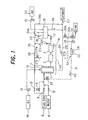
- FIG. 1 is a schematic configurational drawing of the fuel cell power generation system.
- the fuel cell power generation system is a fuel cell power generation system equipped with a fuel reforming device 60 and a fuel cell body 4, as shown in FIG. 1 .
- This fuel cell power generation system includes valves 30a, 32, pipelines 30b, 31, a condenser 34, a pump 35, etc. which constitute raw gas feeding means for feeding a burner exhaust gas 25 (raw gas) discharged from a heating burner 10 of the fuel reforming device 60; and an inert gas formation device 5A which is inert gas formation means containing an oxidizable and reducible oxygen adsorbent 28 disposed in the pipelines 30b, 31 to adsorb oxygen in the burner exhaust gas 25, thereby removing oxygen from the burner exhaust gas 25 and forming an inert gas 40.
- the fuel cell power generation system according to the present example also includes a heater 33 which is adsorbent reduction means for reducing the oxygen adsorbent 28 having adsorbed oxygen.
- the fuel reforming device 60 is equipped with a fuel reformer 1, a CO conversion catalyst reactor 2, and a PROX catalyst reactor 3.
- the reforming of a fuel gas 6 is performed, mainly, in the fuel reformer 1 by mixing the fuel gas 6 and steam, and flowing the mixture through a reforming catalyst layer 7 to cause a steam reforming reaction (CH 4 + H 2 O ⁇ CO + 3H 2 O) generally at a temperature of 500 to 700°C.
- Ru/Al 2 O 3 for example, can be used as a reforming catalyst.
- City gas or LPG (liquefied propane gas), DME (dimethylethanol), or kerosene is used as the fuel gas 6.
- the fuel gas 6 is supplied to the fuel reformer 1 via a main valve 8 and a sub-valve 9. Since the steam reforming reaction is an endothermic reaction, the fuel reformer 1 is provided with the burner 10 as a heat source. Water 11 is supplied to the fuel reformer 1 via a valve 12. The water 12 is converted into steamby an evaporator (not shown) utilizing the heat of the burner 10. The burner 10 is supplied with part of the fuel gas 6 via a valve 13, and air 14 via a pump 15.
- the CO conversion catalyst reactor 2 forms hydrogen from steam and carbon monoxide by a CO conversion (also called CO shift) reaction (CO + H 2 O ⁇ CO 2 + H 2 ) using a CO conversion catalyst layer, and is used to raise the efficiency of reforming by making the effective use of COwhich has been formed by the steam reforming reaction in the fuel reformer 1.
- CO conversion also called CO shift
- HTS high temperature shift catalyst
- LTS low temperature shift catalyst
- HTS high temperature shift catalyst
- LTS low temperature shift catalyst
- HTS high temperature shift catalyst
- LTS low temperature shift catalyst
- HTS high temperature shift catalyst
- LTS low temperature shift catalyst
- Fe 2 O 3 ⁇ Cr 2 O 3 can be used as the HTS catalyst
- CuO ⁇ ZnO for example, can be used as the LTS catalyst.
- the PROX catalyst reactor 3 performs a PReferable OXidization reaction (CO + 1/2O 2 ⁇ CO 2 using a PROX catalyst layer, thereby converting carbon monoxide, which is a toxic substance, into carbon dioxide (carbonic acid gas) , and is used to minimize the carbon monoxide concentration of a reformed gas 16.
- Ru/Al 2 O 3 can be used as the PROX catalyst.
- the PROX reaction is performed at about 100 to 150°C.
- the reformed gas 16, which has been reformed from the fuel gas 6 by passing through the fuel reformer 1, the CO conversion catalyst reactor 2, and the PROX catalyst reactor 3, is supplied to an anode 18 of the fuel cell body 4 via a valve 17.
- a cathode 19 of the fuel cell body 4 is supplied with air 20 via a pump 21.
- An anode exhaust gas (reformed gas after use) 22 discharged from the fuel cell body 4 is returned to the fuel reformer 1 via an anode exhaust gas passage 36 and a valve 38, and is used, for example, as a fuel for the burner 10.
- An unused reformed gas 23, which has been reformed by the fuel reforming device 60, but becomes a surplus for the convenience of power generation load, is also returned to the fuel reformer 1 via a valve 24, the anode exhaust gas passage 36 and the valve 38, and is used, for example, as a fuel for the burner 10.
- the burner exhaust gas 25 discharged from the fuel reformer 1, and cathode exhaust air 26 discharged from the fuel cell body 4 are discharged to a system exhaust gas passage 27.
- the inert gas formation device 5A is mainly composed of the oxygen adsorbent 28 capable of undergoing repeated oxidation and reduction.
- the oxygen adsorbent 28 in the present example is installed outside the fuel reforming device 60 including the fuel reformer 1, the CO conversion catalyst reactor 2, and the PROX catalyst reactor 3.
- the oxygen adsorbent 28 is charged into a suitable container.
- the inlet of the container of the oxygen adsorbent 28 is supplied with part or all of the burner exhaust gas 25 via a burner exhaust gas passage 29, the valve 30a, and the pipeline 30b.
- the outlet of the container of the oxygen adsorbent 28 is connected to the fuel reformer 1 via the pipeline 31 and the valve 32.
- the heater 33 using electricity or the like is annexed to the oxygen adsorbent 28.
- the condenser 34 and the pump 35 are connected sequentially to the pipeline 30b between the valve 30a and the inlet of the container of the oxygen adsorbent 28.
- a valve 37a and a pipeline 37b, which enable the used reformed gas 22 or the unused reformed gas 23 to be supplied from a portion of the anode exhaust gas passage 36 downstream of the valve 38, are connected to a portion of the pipeline 30b upstream of the condenser 34.
- a valve 39a and a pipeline 39b, which discharge the used reformed gas 22 and the unused reformed gas 23 from the upstream side of the valve 38 to the system exhaust gas passage 27, are connected to the anode exhaust gas passage 36.
- the oxygen adsorbent 28 may be any one which can undergo oxidation and reduction.
- any one of Cr (chromium), Mn (manganese), Fe (iron), Co (cobalt), Ni (nickel), Cu (copper), and Zn (zinc) can be used.
- a combination of two or more of Cr, Mn, Fe, Co, Ni, Cu and Zn mentioned here (for example, a Cu/Zn mixture) can be used.
- the LTS catalyst In addition to Cu or Cu/Zn, a substance similar to the LTS catalyst can be used.
- the LTS catalyst such as the Cu/Zn mixture, has its CO conversion function deteriorated upon repeated oxidation and reduction, but its oxidation and reduction function itself does not decline.
- the oxygen adsorbent 28 is not limited in terms of its shape, but preferably, it is of a pellet shape or a honeycomb shape.
- oxygen adsorbent 28 oxygen is adsorbed and removed from the burner exhaust gas 25 according to an oxidation reaction represented by Cu + 1/202 ⁇ CuO.
- This deoxidizing treatment is performed at 100°C or higher, preferably 150°C to 700°C, more preferably 200°C to 400°C. By heating the oxygen adsorbent 28 to 100°C or above, oxygen can be easily removed from the burner exhaust gas 25.
- CuO is reduced to Cu according to a reduction reaction represented by CuO + H 2 atmosphere ⁇ Cu.
- This reductive regeneration treatment is performed at 100°C or higher, preferably 150°C to 700°C, more preferably 200°C to 400°C.
- the valve 32 To carry out purging of the interior of the system with the inert gas 40, the valve 32 is opened.
- the inert gas 40 flows from the fuel reformer 1 and through the CO conversion catalyst reactor 2, the PROX catalyst reactor 3, and the fuel cell body 4, and is discharged from the anode 18 to the system exhaust gas passage 27 via the valve 39a.
- the residual matter, such as moisture which has remained in the fuel reformer 1, the CO conversion catalyst reactor 2, the PROX catalyst reactor 3, and the fuel cell body 4, is thoroughly removed.
- the condenser 34 is actuated to cool the burner exhaust gas 25 through the condenser 34, thereby removing moisture in the burner exhaust gas 25.
- the inert gas 40 which has become dry, is obtained.
- the pump 35 is actuated to increase the volume of the inert gas 40.
- the inert gas 40 may be bypassed without being passed through the fuel cell body 4.
- the oxygen adsorbent 28 is reduced with a hydrogen gas atmosphere for the purpose of regeneration by the time when next purging with the inert gas 40 is carried out within the system.
- the valve 37a is opened to feed the used reformed gas 22 or the unused reformed gas 23 to the oxygen adsorbent 28 via the valve 37a and the pipeline 37b, thereby reducing the oxygen adsorbent 28.
- the heater 33 is actuated (100°C or above) to raise the temperature of the oxygen adsorbent 28 (in the case of Cu, to about 200°C), thereby increasing the efficiency of reduction.
- the heater 33 After completion of reduction, the heater 33 is stopped.
- the condenser 34 is actuated to remove moisture in the reformed gases 22, 23, thereby increasing the efficiency of reduction.
- the pump 35 is actuated to increase the amounts of the reformed gases 22, 23.
- the reformed gases 22, 23 after being used for regeneration of the oxygen adsorbent 28 are preferably returned to the reforming catalyst layer 7 by opening the valve 32, but these reformed gases 22, 23 can also be supplied to the burner 10 via a suitable path.
- the burner 10 is generally adjusted such that the burner exhaust gas 25 contains about 2% of oxygen.
- the internal volume of the system is several liters, and the interior of the system is purged with several times that volume (for example, 10 liters) of the inert gas 40.
- the resulting inert gas 40 is flowed for 1 minute at a flow rate of about 10 liters/minute.
- Cu is used as the oxygen adsorbent 28
- about 1.3 g of Cu is required.
- an oxygen adsorption test was conducted under the testing conditions shown in Table 1 below.
- a Cu/Zn mixture was used as the oxygen adsorbent 28, 20 cc of the Cu/Zn mixture was charged into a container, switching between a gas A for oxygen adsorption and a gas B for reduction is performed so that either gas is introduced into the oxygen adsorbent 28, and an O 2 meter (oxygen concentration sensor) is attached to the outlet of the oxygen adsorbent 28 to measure the oxygen concentration.
- the oxygen adsorption test was conducted at an adsorption temperature of 100°C, 200°C or 300°C, and the gas A at the time of oxygen adsorption at the inlet of the oxygen adsorbent 28 was set to have a composition simulating the burner exhaust gas 25 (O 2 : 2%, CO 2 : 10%, H 2 O: 3%, remainder N 2 ).
- the dwell time of the gas in the oxygen adsorbent 28 was determined mainly based on a space velocity of 5,000 (1/h). Under these conditions, the effect of the adsorption temperature was confirmed.
- Table 2 and FIG. 3 shows that at the adsorption temperature of 100°C, the time during which the oxygen concentration in the gas at the outlet of the oxygen adsorbent 28 remained zero was 14 minutes; at the adsorption temperature of 200°C, the time during which the oxygen concentration in the gas at the outlet of the oxygen adsorbent 28 remained zero was 24 minutes; and at the adsorption temperature of 300°C, the time during which the oxygen concentration in the gas at the outlet of the oxygen adsorbent 28 remained zero was 32 minutes.
- the oxygen adsorbent 28 is heated with the use of the heater 33.
- the oxygen adsorbent 28 may be placed, for example, adjacent to the fuel reforming device 60 (for example, inwardly of the heat insulator).
- the oxygen adsorbent 28 can be held at an appropriate temperature by utilizing the heat of the fuel reforming device 60.
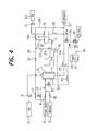
- FIG. 4 is a schematic configurational drawing of the fuel cell power generation system.
- the same parts as those in the aforementioned first example are assigned the same numerals as the numerals used in the descriptions of the a forementioned first example, whereby duplicate explanations are omitted.
- the fuel cell power generation system is a fuel cell power generation system equipped with a fuel reforming device 60 and a fuel cell body 4, as shown in FIG. 4 .
- This fuel cell power generation system includes valves 30a, 32, pipelines 30b, 31, a condenser 34, a pump 35, etc. which constitute raw gas feeding means for feeding a burner exhaust gas 25 (raw gas) discharged from a heating burner 10 of the fuel reforming device 60; and an inert gas formation device 5B, as inert gas formation means containing an oxygen absorbing solution 41, which is disposed between the pipelines 30b and 31 and absorbs oxygen in the burner exhaust gas 25, thereby removing oxygen from the burner exhaust gas 25 and forming an inert gas 40.
- the inert gas formation device 5B is mainly composed of the oxygen absorbing solution 41.
- the oxygen absorbing solution 41 is charged into a tank (container) 42.
- the inlet of the tank 42 is supplied with part or all of the burner exhaust gas 25 via a burner exhaust gas passage 29, the valve 30a, and the pipeline 30b.
- the outlet of the tank 42 is connected to a fuel reformer 1 via the pipeline 31 and the valve 32.
- any liquid having an oxygen absorbing function can be used as the oxygen absorbing solution 41.
- a solution of sodium sulfite Na 2 SO 3
- oxygen is absorbed and removed from the burner exhaust gas 25 in accordance with an oxidation reaction represented by Na 2 SO 3 + 1/2O 2 ⁇ Na 2 SO 4 .
- the fuel cell power generation system according to the present example corresponds to the fuel cell power generation system according to the aforementioned first example ( FIG. 1 ) in which the inert gas formation device 5B utilizing the oxygen absorbing solution 41 instead of the oxygen adsorbent 28 has been applied, and also the heater 33, the valve 37a and the pipeline 37b have been omitted.
- the valve 32 To carry out purging of the interior of the system with the inert gas 40, the valve 32 is opened.
- the inert gas 40 flows from the fuel reformer 1 and through the CO conversion catalyst reactor 2, the PROX catalyst reactor 3, and the fuel cell body 4, and is discharged from the anode 18 to the system exhaust gas passage 27 via the valve 39a.
- the residual matter, such as moisture which has remained in the fuel reformer 1, the CO conversion catalyst reactor 2, the PROX catalyst reactor 3, and the fuel cell body 4, is thoroughly removed.
- the condenser 34 is actuated to cool the burner exhaust gas 25 through the condenser 34, thereby removing moisture in the burner exhaust gas 25.
- the inert gas 40 which has become dry, is obtained.
- the pump 35 is actuated to increase of the volume of the inert gas 40.
- the oxygen absorbing solution 41 which has absorbed oxygen, has its oxygen absorbing capacity gradually saturated. Thus, around a point in time when the oxygen absorbing capacity of the oxygen absorbing solution 41 has approached its saturation, the oxygen absorbing solution 41 is replaced by a new oxygen absorbing solution 41 before next purging. For example, the oxygen absorbing solution 41 is replaced at regular intervals of about 1 year or several years.
- the oxygen absorbing solution 41 when sodium sulfite (Na 2 SO 3 ) is used as the oxygen absorbing solution 41, the amount of sodium sul fite (126 g/mol) needed per year is twice that of oxygen, and is 7.3 mols (about 920 g). If the oxygen absorbing solution is a 20 wt.% aqueous solution, about 4.6 liters of the oxygen absorbing solution 41 will become necessary. Moreover, the tank 42 containing the oxygen absorbing solution 41 is required to have a volume of about 6 to 10 liters.
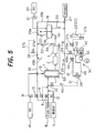
- FIG. 5 is a schematic configurational drawing of the fuel cell power generation system.
- the same parts as those in the aforementioned first example are assigned the same numerals as the numerals used in the descriptions of the aforementioned first example, whereby duplicate explanations are omitted.
- the fuel cell power generation system is a fuel cell power generation system equipped with a fuel reforming device 60 and a fuel cell body 4, as shown in FIG. 5 .
- This fuel cell power generation system has an inert gas formation device 5C as inert gas formation means including valves 37a, 37c, a pipeline 37b, a pump 35, a tank 42, etc. which constitute carbon dioxide recovery means containing an aqueous amine solution 43 supplied with an anode exhaust gas 22 discharged from an anode 18 of the fuel cell body 4 to absorb carbon dioxide in the anode exhaust gas 22, and valves 44, 32, a pipeline 31, a heater 33, etc. which constitute carbon dioxide feeding means for heating the aqueous amine solution 43 of the carbon dioxide recovery means to release carbon dioxide from the aqueous amine solution 43 and feeding the carbon dioxide into the fuel reforming device 60.
- the fuel cell power generation system also includes a valve 45a, a pipeline 45b, etc. constituting raw gas recycling means for supplying the anode exhaust gas 22, from which carbon dioxide has been recovered by the above-mentioned carbon dioxide recovery means, to a burner 10 of the fuel reforming device 60.
- the fuel, cell power generation system further includes a condenser 34, which is moisture recovery means for recovering moisture from carbon dioxide fed into the fuel reforming device 60, and a pipeline 46, etc. as moisture recycling means for returning the moisture recovered by the condenser 34 to the aqueous amine solution 43.
- a condenser 34 which is moisture recovery means for recovering moisture from carbon dioxide fed into the fuel reforming device 60, and a pipeline 46, etc. as moisture recycling means for returning the moisture recovered by the condenser 34 to the aqueous amine solution 43.
- the inert gas formation device 5C is mainly composed of the aqueous amine solution 43 and the heater 33.
- the aqueous amine solution 43 is charged into a tank 42.
- the inlet of the tank 42 is supplied with part of the anode exhaust gas 22 from between the valve 38 and the valve 39a on the anode exhaust gas passage 36 via the valve 37a, pipeline 37b, valve 37c and pump 35.
- As the heater 33 a heater acting with an alternating current power source (AC) is applied.
- AC alternating current power source
- a vapor phase portion within the tank 42 (i.e., a space above the solution) is connected to the fuel reformer 1 via the pipeline 31 and the valve 32.
- a pressure regulating valve 44 and the condenser 34 are connected sequentially.
- the vapor phase portion of the tank 42 is also connected to a portion of the anode exhaust gas passage 36 downstream of the valve 38 via the valve 45a and the pipeline 45b.
- amine various amines may be used, such as a primary amine.
- a carbon dioxide gas absorption reaction represented by 2RNH 2 + CO 2 ⁇ (RNH 3 ) + + (RNHCOO) -
- RNH 3 carbon dioxide gas absorption reaction
- RNH 3 carbon dioxide gas dissipation reaction
- the fuel cell power generation system according to the present example is the fuel cell power generation system according to the aforementioned first example ( FIG. 1 ) in which there has been applied the inert gas formation device 5C utilizing the aqueous amine solution 43 instead of the oxygen adsorbent 28, the condenser 34 has been installed downstream of the inert gas formation device 5C, the valve 37c, pressure regulating valve 44, valve 45a and pipeline 45b have been newly added, and the valve 30a and the pipeline 30 have been omitted.
- the required amount of amine will be described. As an example, assume that the amount of release of the carbon dioxide gas necessary per purging is 1 mol (22.4 liters). In this case, the amount of amine necessary to absorb 1 mol of carbon dioxide gas for one purging is 2 mols (122 g), if the type of the amine is MEA (molecular weight 61). Provided that the aqueous amine solution is a 50 wt.% aqueous solution, about 250 ml of the aqueous aminesolutionisneeded. If it is assumed that the volume of the container 42, including the vapor phase portion, is 600 ml, the container 42 measures 50 mm in diameter by 300 mm in height, and the height of the surface of the solution is about 130 mm.
- FIG. 6 is a schematic configurational drawing of the fuel cell power generation system.
- the same parts as those in the aforementioned first example are assigned the same numerals as the numerals used in the descriptions of the aforementioned first example, whereby duplicate explanations are omitted.
- the fuel cell power generation system according to the present embodiment is the fuel cell power generation system according to the first example ( FIG. 1 ) in which the place of installation of the oxygen adsorbent 28 has been changed, and the heater 33, valve 37a and pipeline 37b have been omitted.
- the oxygen adsorbent 28 capable of undergoing repeated oxidation and reduction is, in the present embodiment, installed between a fuel reformer 1 and a CO conversion catalyst reactor 2, in other words, between a reforming catalyst layer 7 and a CO conversion catalyst layer, within a fuel reforming device 60 including the fuel reformer 1, the CO conversion catalyst reactor 2, and a PROX catalyst reactor 3, and is charged into a suitable container.
- the inlet of the container of the oxygen adsorbent 28 is connected to the fuel reformer 1, while the outlet of the container of the oxygen adsorbent 28 is connected to the CO conversion catalyst reactor 2.
- a burner exhaust gas passage 29 is connected to the reforming catalyst layer 7 of the fuel reformer 1 via a valve 30a, a pipeline 30b, a condenser 34, a pump 35, a pipeline 31 and a valve 32.
- the oxygen adsorbent 28 is installed outside the fuel reforming device 60 (i.e., in the raw gas feeding means).
- the oxygen adsorbent 28 is installed within the fuel reforming device 60 (between the reforming catalyst layer 7 and the CO conversion catalyst layer).
- the valve 30a and the valve 32 are opened, whereby part or all of the burner exhaust gas 25 is taken into the reforming catalyst layer 7 of the fuel reformer 1 from the burner exhaust gas passage 29 via the valve 30a, the pipeline 30b, the condenser 34, the pump 35, the pipeline 31 and the valve 32.
- the burner exhaust gas 25 is added to the oxygen adsorbent 28 from the inlet of the container.
- the burner exhaust gas 25 has oxygen inside it adsorbed and removed by the oxygen adsorbent 28, is thereby changed to an inert gas 40, and is then fed sequentially to the CO conversion catalyst reactor 2, PROX catalyst reactor 4 and fuel cell body 4.
- valve 30a and the valve 32 are closed, and a reformed gas 16 formed by the reforming catalyst layer 7 is added to the oxygen adsorbent 28 through the inlet of the container and, through the oxygen adsorbent 28, is added to the CO conversion catalyst reactor 2.
- the burner exhaust gas 25 containing oxygen flows through the reforming catalyst layer 7.
- a precious metal catalyst such as Ru, which is an oxidation-resistant catalyst not deteriorated by oxygen, unlike a CO conversion catalyst, such as an LTS catalyst, used in a CO conversion reaction.
- the oxygen adsorbent 28 is disposed between the reforming catalyst layer 7 which is not deteriorated by oxygen, and the CO conversion catalyst layer which is liable to deterioration by oxygen.
- the CO conversion catalyst layer is passed by the inert gas 40 rid of oxygen, so that the CO conversion catalyst is free from deterioration.
- the oxygen adsorbent 28 is reduced when the reformed gas 16 from the reforming catalyst layer 7 passes therethrough during the reforming operation.
- the oxygen adsorption temperature and the oxygen release temperature of the oxygen adsorbent 28 are 200°C to 300°C, based on the results of the tests described in the aforementioned first embodiment.
- the gas temperature on the side upstream of the CO conversion catalyst layer is kept at about 250°C, thereby obviating the need for an electrical heater (see the numeral 33 in FIG. 1 ) or the like for heating the oxygen adsorbent 28.
- the oxygen adsorbent 28 removes oxygen in the burner exhaust gas 25, which has passed through the reforming catalyst layer 7, by adsorbing the oxygen. That is, oxygen is removed from the burner exhaust gas 25 by the oxygen adsorbent 28, ahead of the CO conversion catalyst layer which is prone to deterioration by oxygen.
- the inert gas 40 cleared of oxygen, flows through the CO conversion catalyst reactor 2, the PROX catalyst reactor 3, and the anode of the fuel cell body 4, and is discharged to the system exhaust gas passage 27 via the valve 39a.
- the residual matter, such as moisture, which has remained in the CO conversion catalyst reactor 2, the PROX catalyst reactor 3, and the fuel cell body 4 can be thoroughly removed.
- the oxygen adsorbent 28, which has adsorbed oxygen, is automatically reduced in the present embodiment, because the reformed gas 16 from the fuel reformer 1 is added to the oxygen adsorbent 28 during the next operation of the system, in other words, during the next reforming operation.
- Heat generated by the oxidation-reduction reaction of the oxygen adsorbent 28 may adversely affect the catalyst within the fuel reforming device 60, especially, LTS catalyst. To prevent this adverse influence, it is a feature of the invention to provide a heat insulating layer using, for example, vacuum heat insulation, or a heat exchange portion, between the oxygen adsorbent 28 and the CO conversion catalyst reactor 2.
- FIG. 7 is a schematic configurational drawing of the fuel cell power generation system.
- the same parts as those in the aforementioned first example are assigned the same numerals as the numerals used in the descriptions of the aforementioned first example, whereby duplicate explanations are omitted.
- the fuel cell power generation system according to the present example is the fuel cell power generation system according to the first example ( FIG. 1 ) in which the place of installation of the oxygen adsorbent 28 has been changed, and the heater 33 has been omitted.
- the oxygen adsorbent 28 capable of undergoing repeated oxidation and reduction is, in the present example, installed in a portion of a fuel reformer 1 upstream of a reforming catalyst layer 7, in other words, between inlet ports of the fuel reformer 1 for a fuel gas 6 and water 11 and the reforming catalyst layer 7, within a fuel reforming device 60, and is packed into other layer communicating with the reforming catalyst layer 7.
- the resulting inert gas 40 flows through the reforming catalyst layer 7 within the fuel reformer 1, the CO conversion catalyst reactor 2, the PROX catalyst reactor 3, and the anode 18 of the fuel cell body 4, and is discharged to the system exhaust gas passage 27 via the valve 39a.
- the residual matter, such as moisture which has remained in the reforming catalyst layer 7 within the fuel reformer 1, the CO conversion catalyst reactor 2, the PROX catalyst reactor 3, and the fuel cell body 4, can be thoroughly removed.
- the condenser 34 is actuated, and the burner exhaust gas 25 is passed through the condenser 34, whereby the burner exhaust gas 25 is cooled, and moisture in the burner exhaust gas 25 is removed. Consequently, the inert gas, which has become dry, is obtained. In keeping the fuel cell body 4 in humid condition, the inert gas 40 may be bypassed without being passed through the fuel cell body 4.
- the oxygen adsorbent 28 is reduced with a hydrogen gas atmosphere for the purpose of regeneration by the time when next purging of the interior of the system with the inert gas 40 is carried out.
- the valve 37a is opened to feed the used reformed gas 22 or the unused reformed gas 23 to the oxygen adsorbent 28 via the valve 37a and the pipeline 37b, thereby reducing the oxygen adsorbent 28.
- the reformed gases 22, 23 after being used for regeneration of the oxygen adsorbent 28 are preferably returned to the reforming catalyst layer 7 by opening the valve 32, but these reformed gases 22, 23 can also be supplied to the burner 10 by a suitable path.
- a water adsorbent 52 may be provided between the fuel reformer 1 and the CO conversion catalyst reactor 2 as shown in FIG. 8 , instead of using the condenser 34, the pump 35, etc.
- the water adsorbent 52 silica gel, zeolite, or molecular sieve, for example, can be applied.
- the reforming catalyst layer 7 and the layer of the oxygen adsorbent 28 are separately provided within the fuel reformer 1, as shown in FIG. 7 .
- the oxygen adsorbent 28 can be provided in the reforming catalyst layer 7, that is, a layer 54 of a mixture of a reforming catalyst and an oxygen adsorbent can be provided within the fuel reformer 1, as shown in FIG. 9 .
- This contrivance makes it possible to avoid a double-layer configuration within the fuel reformer 1 as shown in FIG. 7 , and simplify the structure of the fuel reformer 1.
- FIG. 10 is a schematic configurational drawing of the fuel cell power generation system.
- the same parts as those in the aforementioned first example are assigned the same numerals as the numerals used in the descriptions of the aforementioned first example, whereby duplicate explanations are omitted.
- the fuel cell power generation system according to the present example is the fuel cell power generation system according to the first example ( FIG. 1 ) in which the positions of connection of the valve 30a and the pipeline 30b have been changed.
- valve 30a and the pipeline 30b are brought into communication with the outside without being connected to the burner exhaust gas passage 29.
- the burner exhaust gas 25 is used as the starting material (raw gas) for the inert gas 40.
- air outside the system is used as the starting material (raw gas) for the inert gas 40.
- the valve 30a and the valve 32 are opened, and the condenser 34 and the pump 35 are actuated, whereby air from the outside is taken into the oxygen adsorbent 28. Oxygen in this air is adsorbed and removed by the oxygen adsorbent 28 to form the inert gas 40.
- the inert gas 40 is then fed sequentially to the CO conversion catalyst reactor 2, PROX catalyst reactor 4 and fuel cell body 4.
- the inert gas 40 is formed with the use of outside air.
- the inert gas 40 can be formed, for example, with the use of exhaust air 26 discharged from the cathode 19 of the fuel cell body 4.
- junction between the anode exhaust gas passage 36 and the pipeline 37b in the aforementioned first and third examples may be located upstream or downstream of the valve 38.
- the inert gas 40 can be formed by using air outside the system as the raw gas, or the inert gas 40 can be formed by using the exhaust air 26, which has been discharged from the cathode 19 of the fuel cell body 4, as the raw gas.
- the inert gas formation methods or means in the aforementioned first to fifth examples and first embodiment may be combined in suitable plural numbers to form the inert gas, and the inert gas can be used for purging.
- a desulfurization catalyst reactor provided with a desulfurization catalyst can be provided upstream of the reforming catalyst reactor 1.
- zeolite or the like can be applied as the desulfurization catalyst.
- Such a desulfurization catalyst reactor generally operates at the ordinary temperature.
- the fuel cell power generation system is a fuel cell power generation system equipped with a fuel reforming device and a fuel cell body, the fuel cell power generation system comprising: raw gas feeding means for feeding into the fuel reforming device at least one raw gas among a burner exhaust gas discharged from a heating burner of the fuel reforming device, exhaust air discharged from a cathode of the fuel cell body, and air from outside the system; and inert gas formation means including an oxidizable and reducible oxygen adsorbent which adsorbs oxygen in the raw gas to remove oxygen from the raw gas and form an inert gas.
- the inert gas with a lower (substantially no) oxygen content than those by the earlier technologies can be formed.
- the LTS catalyst for CO conversion is not deteriorated by purging with the inert gas.
- the oxygen adsorbent can be reused multiple times by undergoing reduction after adsorbing oxygen.
- purging can be performed while the inert gas is being formed. As a result, residual matter such as a combustible gas or moisture, and oxygen can be reliably removed, without being left within the fuel reforming device, in a simple manner with a compact configuration at a low cost.
- the fuel cell power generation system according to the fourth example has adsorbent reduction means for reducing the oxygen adsorbent which has adsorbed oxygen.
- the oxygen adsorbent can be reused many times.
- the oxygen adsorbent is disposed in a location between a reforming catalyst layer and a CO conversion catalyst layer provided in the fuel reforming device.
- the oxygen adsorbent is disposed between the reforming catalyst layer and the CO conversion catalyst layer provided in the fuel reforming device, a special means for heating the oxygen adsorbent is unnecessary.
- the oxygen absorber preferably comprises at least one of chromium (Cr), manganese (Mn), iron (Fe), cobalt (Co), nickel (Ni), copper (Cu), and zinc (Zn).
- Cr chromium
- Mn manganese
- Fe iron
- Co cobalt
- Ni nickel
- Cu copper
- Zn zinc
- the method for operating a fuel cell power generation system according to the invention is a method for operating the fuel cell power generation system according to the invention, comprising forming the inert gas by the inert gas formation means, and removing residual matter, which has remained within the fuel reforming device, with the inert gas for inert gas purging, in stopping an operation for power generation.
- the inert gas with a lower (substantially no) oxygen content than those by the earlier technologies can be formed.
- the LTS catalyst for CO conversion is not deteriorated by purging with the inert gas.
- purging can be performed while the inert gas is being formed.
- the oxygen adsorbent can be reused many times by being reduced after adsorbing oxygen. As a result, residual matter such as a combustible gas or moisture, and oxygen can be reliably removed, without being left within the fuel reforming device, in a simple manner with a compact configuration at a low cost.
- the method for operating a fuel cell power generation system preferably comprises reducing the oxygen adsorbent of the inert gas formation means with a reformed gas formed by reforming in the fuel reforming device, or an anode exhaust gas discharged from an anode of the fuel cell body, thereby performing regeneration of the oxygen adsorbent of the inert gas formation means.
- a special reducing agent is not necessary.
- the method for operating a fuel cell power generation system according to the invention preferably comprises performing the regeneration in carrying out an operation for power generation.
- regeneration treatment can be performed with high efficiency.
- the method for operating a fuel cell power generation system preferably comprises removing the residual matter within the fuel reforming device with steam before purging the interior of the fuel reforming device with the inert gas.
- the amount of the inert gas may be small, and the amount of the oxygen adsorbent, the oxygen absorbing solution, or the aqueous amine solution may be small.
- the method for operating a fuel cell power generation system preferably comprises removing the residual matter within the fuel reforming device with steam, then flowing only air to the burner of the fuel reforming device to cool the fuel reforming device, and then purging the interior of the fuel reforming device with the inert gas.
- the amount of the inert gas may be small, and the amount of the oxygen adsorbent, the oxygen absorbing solution, or the aqueous amine solution may be small.
- the steam for removing the residual matter within the fuel reforming device has a fuel gas incorporated therein, the fuel gas being in an amount necessary and sufficient to prevent oxidation within the fuel reforming device.
- the method for operating a fuel cell power generation system preferably comprises actuating only the burner of the fuel reforming device to heat and raise the temperature of the fuel reforming device; feeding steam to the fuel reforming device during a rise in the temperature of the fuel reforming device, the steam containing a necessary and sufficient amount of a fuel gas to prevent oxidation within the fuel reforming device; and supplying the fuel gas, in a necessary amount according to the actuation of the fuel cell body, after completion of the rise in the temperature of the fuel reforming device, to start an operation for power generation.
- the rise in the temperature of the fuel reforming device is rapid, and the oxidation of the interior of the fuel reforming device with steam can be prevented in a simple manner at a low cost.
- the present invention can provide a fuel cell power generation system, which can reliably remove residual matter, such as a combustible gas or moisture, and oxygen, without leaving them within a fuel reforming device, at a low cost and with a compact configuration, and a method for operating the fuel cell power generation system.
- the present invention can afford industrially very beneficial results.
Landscapes
- Chemical & Material Sciences (AREA)
- Manufacturing & Machinery (AREA)
- Organic Chemistry (AREA)
- Life Sciences & Earth Sciences (AREA)
- Engineering & Computer Science (AREA)
- Sustainable Development (AREA)
- Sustainable Energy (AREA)
- Chemical Kinetics & Catalysis (AREA)
- Electrochemistry (AREA)
- General Chemical & Material Sciences (AREA)
- Inorganic Chemistry (AREA)
- Analytical Chemistry (AREA)
- Fuel Cell (AREA)
Claims (9)
- Ein Brennstoffzellen-Stromerzeugungssystem, ausgerüstet mit einer Brennstoff-Reformierungsvorrichtung (60) und einem Brennstoffzellen-Körper (4), mit:Rohgaseinspeisungsmitteln zum Einspeisen in die Brennstoff-Reformierungsvorrichtung (60) mindestens eines Rohgases aus einem Brennerabgas (25), welches von einem Heizungsbrenner (10) der Brennstoff-Reformierungsvorrichtung (60) ausgestoßen wird, Abgas (26), welches von einer Kathode (19) des Brennstoffzellen-Körpers (4) ausgestoßen wird, und Luft (20) von außerhalb des Systems, undInertgas-Bildungsmittel (5A) mit einem oxidierbaren und reduzierbaren Sauerstoff-Adsorptionsmittel (28), um Sauerstoff in dem Rohgas derart zu adsorbieren, um Sauerstoff von dem Rohgas zu entfernen und ein Inertgas (40) zu erzeugen,wobei das Sauerstoff-Adsorptionsmittel (28) an mindestens einer Position aus einer Position zwischen einer Reformierungs-Katalysatorschicht (7) und einer CO-Konvertierungs-Katalysatorschicht (2), die in der Brennstoff-Reformierungsvorrichtung (60) vorgesehen sind, einer Position in der Brennstoff-Reformierungs-Vorrichtung (60), stromauf der Reformierungs-Katalysatorschicht (7), und einer Position in der Reformierungs-Katalysatorschicht, die in der Brennstoff-Reformierungsvorrichtung (60) vorgesehen ist, angeordnet ist,wobei das Sauerstoff-Adsorptionsmittel (28), welches Sauerstoff adsorbiert hat, geeignet ist, dass es durch Einspeisung reformierten Gases (16;22,23), welches durch Reformierung in der Brennstoff-Reformierungsvorrichtung (60) zu dem Sauerstoff-Adsorptionsmittel (28) gebildet wurde, reduziert wird,wobei das Sauerstoff-Adsorptionsmittel (28) an einer Position zwischen einer Reformierungs-Katalysatorschicht (7) und einer CO-Konvertierungs-Katalysatorschicht (2), die in der Brennstoff-Reformierungsvorrichtung (60) vorgesehen sind, angeordnet ist, undwobei eine wärmeisolierende Schicht oder ein Wärmetauscherabschnitt zwischen dem Sauerstoff-Adsorptionsmittel (28) und der CO-Konvertierungs-Katalysatorschicht (2) vorgesehen ist.
- Das Brennstoffzellen-Stromerzeugungssystem gemäß Anspruch 1, wobei
das Sauerstoff-Adsorptionsmittel (28;54) mindestens eines aus Chrom (Cr), Mangan (Mn), Eisen (Fe), Kobalt (Co), Nickel (Ni), Kupfer (Cu), und Zink (Zn) enthält. - Ein Verfahren zum Betreiben des Brennstoffzellen-Stromerzeugungssystems gemäß einem der Ansprüche 1 und 2, mit:Bilden des Inertgases (40) mit dem Inertgas-Bildungsmittel (5A), und Entfernen von Reststoffen, welche in der Brennstoff-Reformierungsvorrichtung (60) verblieben sind, mit dem Inertgas (40) zum Inertgasspülen, beim Stoppen eines Stromerzeugungsbetriebs.
- Das Verfahren zum Betreiben des Brennstoffzellen-Stromerzeugungssystems gemäß Anspruch 3, mit:Reduzieren des Sauerstoff-Adsorptionsmittels (28) mit einem reformierten Gas (16,23), welches durch Reformierung in der Brennstoff-Reformierungsvorrichtung (60) erzeugt wurde, oder einem Anoden-Abgas (22), welches von einer Anode (18) des Brennstoffzellenkörpers (4) ausgetragen wurde, und dadurch Durchführen einer Regeneration des Sauerstoff-Adsorptionsmittels (28).
- Das Verfahren zum Betreiben des Brennstoffzellen-Stromerzeugungssystems gemäß Anspruch 4, mit:Durchführen der Regeneration beim Ausführen eines Stromerzeugungsbetriebs.
- Das Verfahren zum Betreiben des Brennstoffzellen-Stromerzeugungssystems gemäß einem der Ansprüche 3 bis 5, mit:Entfernen der Reststoffe in der Brennstoff-Reformierungsvorrichtung (60) mit Dampf, vor einem Spülen eines Innenbereichs der Brennstoff-Reformierungsvorrichtung (60) mit dem Inertgas (40).
- Das Verfahren zum Betreiben des Brennstoffzellen-Stromerzeugungssystems gemäß Anspruch 6, mit:Entfernen der Reststoffe in der Brennstoff-Reformierungsvorrichtung (60) mit Dampf,anschließendem Zuströmen nur von Luft zu dem Brenner (10) der Brennstoff-Reformierungsvorrichtung (60), um die Brennstoff-Reformierungsvorrichtung (60) zu kühlen, undanschließendem Spülen des Innenbereichs der Brennstoff-Reformierungsvorrichtung (60) mit dem Inertgas (40).
- Das Verfahren zum Betreiben des Brennstoffzellen-Stromerzeugungssystems gemäß Anspruch 6 oder 7, wobei
der Dampf zum Entfernen der Reststoffe in der Brennstoff-Reformierungsvorrichtung (60) ein Brennstoffgas (6) enthält, wobei das Brennstoffgas (6) in einer Menge vorliegt, die notwendig und ausreichend ist, um Oxidation in der Brennstoff-Reformierungsvorrichtung (60) zu verhindern. - Ein Verfahren zum Betreiben des Brennstoffzellen-Stromerzeugungssystems gemäß einem der Ansprüche 3 bis 8, mit:Betätigen nur des Brenners (10) der Brennstoff-Reformierungsvorrichtung (60) zum Erwärmen und Erhöhen einer Temperatur der Brennstoff-Reformierungsvorrichtung (60),Einspeisen von Dampf in die Brennstoff-Reformierungsvorrichtung (60), während einem Anstieg der
Temperatur der Brennstoff-Reformierungsvorrichtung (60), wobei der Dampf eine notwendige und ausreichende Menge eines Brennstoffgases (6) enthält, um Oxidation in der Brennstoff-Reformierungsvorrichtung (60) zu verhindern, undZuführen des Brennstoffgases (6) in einer notwendigen Menge gemäß einer Betätigung des Brennstoffzellenkörpers (4), nach Abschluss des Anstiegs der Temperatur der Brennstoff-Reformierungsvorrichtung (60), um einen Betrieb zur Stromerzeugung zu beginnen.
Applications Claiming Priority (5)
| Application Number | Priority Date | Filing Date | Title |
|---|---|---|---|
| JP2002130315 | 2002-05-02 | ||
| JP2002130315 | 2002-05-02 | ||
| JP2002198615 | 2002-07-08 | ||
| JP2002198615 | 2002-07-08 | ||
| PCT/JP2003/005353 WO2003094273A1 (en) | 2002-05-02 | 2003-04-25 | Fuel cell power generation system and method for operating the same |
Publications (3)
| Publication Number | Publication Date |
|---|---|
| EP1513207A1 EP1513207A1 (de) | 2005-03-09 |
| EP1513207A4 EP1513207A4 (de) | 2009-12-02 |
| EP1513207B1 true EP1513207B1 (de) | 2012-05-23 |
Family
ID=29405310
Family Applications (1)
| Application Number | Title | Priority Date | Filing Date |
|---|---|---|---|
| EP03719202A Expired - Lifetime EP1513207B1 (de) | 2002-05-02 | 2003-04-25 | Brennstoffzellen-stromerzeugungssystem und verfahren zu seinem betrieb |
Country Status (6)
| Country | Link |
|---|---|
| US (1) | US7387650B2 (de) |
| EP (1) | EP1513207B1 (de) |
| JP (1) | JP4444098B2 (de) |
| CN (1) | CN100336259C (de) |
| CA (1) | CA2479660C (de) |
| WO (1) | WO2003094273A1 (de) |
Families Citing this family (26)
| Publication number | Priority date | Publication date | Assignee | Title |
|---|---|---|---|---|
| JP4421178B2 (ja) * | 2002-09-18 | 2010-02-24 | 本田技研工業株式会社 | 燃料電池スタック |
| JP4486353B2 (ja) * | 2003-12-05 | 2010-06-23 | パナソニック株式会社 | 水素生成装置および水素生成装置の作動停止方法並びに燃料電池発電装置 |
| US20060110634A1 (en) * | 2004-11-24 | 2006-05-25 | Volker Formanski | Method and apparatus for preventing condensation in cathode exhaust conduit of fuel cell |
| DE202004020318U1 (de) * | 2004-12-10 | 2005-03-24 | Europ Fuel Cell Gmbh | Brennstoffzellenheizgerät |
| JP2006286472A (ja) * | 2005-04-01 | 2006-10-19 | Toshiba Fuel Cell Power Systems Corp | 燃料処理装置、燃料電池発電装置及びその起動方法 |
| JP2006294466A (ja) * | 2005-04-12 | 2006-10-26 | Mitsubishi Electric Corp | 燃料電池発電システム |
| JP4795741B2 (ja) * | 2005-07-25 | 2011-10-19 | ウチヤ・サーモスタット株式会社 | 窒素ガス発生装置及びそれを用いた燃料電池発電システム |
| US7615304B2 (en) * | 2005-10-28 | 2009-11-10 | General Electric Company | SOFC systems to power a liquid or gas fuel pumping station |
| JP4918255B2 (ja) * | 2005-12-22 | 2012-04-18 | ウチヤ・サーモスタット株式会社 | 窒素ガス発生装置 |
| US20070154745A1 (en) * | 2005-12-29 | 2007-07-05 | Michael Penev | Purging a fuel cell system |
| JP5065605B2 (ja) * | 2006-03-02 | 2012-11-07 | Jx日鉱日石エネルギー株式会社 | 水素製造装置および燃料電池システム並びにその運転方法 |
| JP4724029B2 (ja) * | 2006-03-27 | 2011-07-13 | アイシン精機株式会社 | 改質装置の運転停止方法 |
| KR100759664B1 (ko) * | 2006-09-12 | 2007-09-17 | 삼성에스디아이 주식회사 | 퍼징 장치가 구비된 연료전지 시스템 및 그 가동 정지 방법 |
| DE102006046676A1 (de) * | 2006-09-29 | 2008-04-17 | J. Eberspächer GmbH & Co. KG | Brennstoffzellensystem und zugehöriges Betriebsverfahren |
| DE102007023417A1 (de) * | 2007-05-18 | 2008-11-20 | Daimler Ag | Heizvorrichtung für Kondensatableiter |
| DE102008013150B4 (de) * | 2008-03-07 | 2012-01-26 | Airbus Operations Gmbh | Mischsystem und Verfahren zur Inertisierung eines Gasvolumens sowie deren Verwendung |
| JP5487563B2 (ja) * | 2008-06-19 | 2014-05-07 | カシオ計算機株式会社 | 電子機器 |
| CA2770880C (en) * | 2009-08-24 | 2018-10-16 | Cellera, Inc. | Systems and methods of securing immunity to air co2 in alkaline fuel cells |
| EP2336083A1 (de) * | 2009-12-17 | 2011-06-22 | Topsøe Fuel Cell A/S | Gasgenerator und Verfahren zur Umwandlung eines Brennstoffs in ein sauerstoffarmen Gases und/oder wasserstoffangereicherten Gases |
| JP2012022968A (ja) * | 2010-07-16 | 2012-02-02 | Mitsubishi Heavy Ind Ltd | 燃料電池発電システム |
| US8945368B2 (en) | 2012-01-23 | 2015-02-03 | Battelle Memorial Institute | Separation and/or sequestration apparatus and methods |
| JP5941706B2 (ja) * | 2012-03-01 | 2016-06-29 | 株式会社ブリヂストン | 不活性ガスの製造方法 |
| AT518956B1 (de) * | 2016-08-02 | 2019-04-15 | Avl List Gmbh | Verfahren zum herunterfahren einer generatoreinheit mit einer brennstoffzellenvorrichtung |
| JP7213217B2 (ja) * | 2020-10-30 | 2023-01-26 | 三菱重工業株式会社 | 燃料電池発電システム、及び、燃料電池発電システムの制御方法 |
| KR102794976B1 (ko) * | 2022-02-10 | 2025-04-10 | 엘지전자 주식회사 | 연료전지 시스템 및 그 동작방법 |
| CN117154153B (zh) * | 2023-09-20 | 2024-04-30 | 江苏核电有限公司 | 一种氢能燃料电池备用系统及其使用方法 |
Family Cites Families (26)
| Publication number | Priority date | Publication date | Assignee | Title |
|---|---|---|---|---|
| JPS5312902B2 (de) * | 1972-03-27 | 1978-05-06 | ||
| US4287170A (en) * | 1980-03-06 | 1981-09-01 | Erickson Donald C | Nitrogen and oxygen via chemical air separation |
| JPS60112263A (ja) * | 1983-11-24 | 1985-06-18 | Mitsubishi Electric Corp | 燃料電池発電装置 |
| JPS6124155A (ja) * | 1984-07-13 | 1986-02-01 | Mitsubishi Electric Corp | 燃料電池発電システム |
| JPH03112263A (ja) * | 1989-09-26 | 1991-05-13 | Nec Corp | ファクシミリ装置の診断方式 |
| US5248567A (en) * | 1991-12-24 | 1993-09-28 | Kabushiki Kaisha Toshiba | Power generation plant including fuel cell |
| JP3515789B2 (ja) | 1992-01-27 | 2004-04-05 | 株式会社東芝 | 燃料電池発電プラント |
| JP3267997B2 (ja) * | 1992-01-31 | 2002-03-25 | 株式会社東芝 | 燃料電池発電プラント |
| JPH06203865A (ja) * | 1993-01-06 | 1994-07-22 | Sanyo Electric Co Ltd | 燃料電池システム |
| JPH07169493A (ja) | 1993-12-17 | 1995-07-04 | Toshiba Corp | 燃料電池発電プラントの可燃性ガスパージ装置 |
| JP3276043B2 (ja) * | 1995-03-10 | 2002-04-22 | 英史 平井 | 新規な複合体およびその製造方法、ならびに該複合体よりなる酸素吸着剤 |
| JPH09330731A (ja) | 1996-04-11 | 1997-12-22 | Mitsui Petrochem Ind Ltd | 燃料電池発電における炭酸ガス、窒素ガス及びアルゴンガスの回収、固定方法 |
| US7138046B2 (en) * | 1996-06-06 | 2006-11-21 | World Hydrogen Energy Llc | Process for production of hydrogen from anaerobically decomposed organic materials |
| JPH1126004A (ja) * | 1997-07-02 | 1999-01-29 | Toshiba Corp | 発電システム |
| JPH11191426A (ja) * | 1997-12-26 | 1999-07-13 | Sanyo Electric Co Ltd | 燃料電池発電システム |
| US6153163A (en) | 1998-06-03 | 2000-11-28 | Praxair Technology, Inc. | Ceramic membrane reformer |
| US6200696B1 (en) * | 1999-02-16 | 2001-03-13 | Energy Research Corporation | Internal reforming fuel cell assembly with simplified fuel feed |
| JP4106801B2 (ja) | 1999-03-24 | 2008-06-25 | 松下電工株式会社 | 燃料電池発電システム |
| JP2000277137A (ja) | 1999-03-24 | 2000-10-06 | Matsushita Electric Works Ltd | 燃料電池発電システムの残留ガスのパージ方法 |
| JP2001180908A (ja) | 1999-12-27 | 2001-07-03 | Matsushita Electric Ind Co Ltd | 水素発生装置およびその起動方法、停止方法 |
| JP2002020102A (ja) * | 2000-06-30 | 2002-01-23 | Mitsubishi Kakoki Kaisha Ltd | 水素製造装置の起動方法およびその停止方法 |
| JP2002034102A (ja) | 2000-07-14 | 2002-01-31 | Fuji Electric Co Ltd | 燃料電池車両と同車両用改質器の停止方法 |
| JP4533515B2 (ja) * | 2000-08-16 | 2010-09-01 | 三菱重工業株式会社 | 合成ガスの製造方法 |
| JP2002110207A (ja) * | 2000-10-03 | 2002-04-12 | Nippon Mitsubishi Oil Corp | 燃料電池システムおよびその運転方法 |
| US6620537B2 (en) * | 2001-02-15 | 2003-09-16 | Ralph C. Struthers | Hydrocarbon fueled hydrogen fuel generator system and apparatus in combination with hydrogen fuel cells |
| JP2002280038A (ja) | 2001-03-21 | 2002-09-27 | Matsushita Electric Ind Co Ltd | 燃料電池発電システム |
-
2003
- 2003-04-25 CA CA002479660A patent/CA2479660C/en not_active Expired - Fee Related
- 2003-04-25 EP EP03719202A patent/EP1513207B1/de not_active Expired - Lifetime
- 2003-04-25 US US10/509,741 patent/US7387650B2/en not_active Expired - Fee Related
- 2003-04-25 WO PCT/JP2003/005353 patent/WO2003094273A1/ja not_active Ceased
- 2003-04-25 CN CNB038094924A patent/CN100336259C/zh not_active Expired - Fee Related
- 2003-04-25 JP JP2004502393A patent/JP4444098B2/ja not_active Expired - Fee Related
Also Published As
| Publication number | Publication date |
|---|---|
| EP1513207A4 (de) | 2009-12-02 |
| CA2479660A1 (en) | 2003-11-13 |
| EP1513207A1 (de) | 2005-03-09 |
| CN100336259C (zh) | 2007-09-05 |
| CA2479660C (en) | 2009-11-24 |
| US7387650B2 (en) | 2008-06-17 |
| JPWO2003094273A1 (ja) | 2005-09-08 |
| US20050112423A1 (en) | 2005-05-26 |
| CN1650459A (zh) | 2005-08-03 |
| JP4444098B2 (ja) | 2010-03-31 |
| WO2003094273A1 (en) | 2003-11-13 |
Similar Documents
| Publication | Publication Date | Title |
|---|---|---|
| EP1513207B1 (de) | Brennstoffzellen-stromerzeugungssystem und verfahren zu seinem betrieb | |
| US7524344B2 (en) | Carbon monoxide adsorption for carbon monoxide clean-up in a fuel cell system | |
| US9112201B2 (en) | Hydrogen production apparatus, fuel cell system and operation method thereof | |
| US7361199B2 (en) | Combined water gas shift reactor/carbon dioxide adsorber for use in a fuel cell system | |
| US7763086B2 (en) | Hydrogen purification process and system | |
| US7276095B2 (en) | Fuel processor module for hydrogen production for a fuel cell engine using pressure swing adsorption | |
| JP2009117054A (ja) | 高温作動燃料電池による発電方法及びシステム | |
| JP2005179083A (ja) | 水素製造装置および燃料電池システム並びにその運転方法 | |
| JP2006342014A (ja) | 高純度水素製造方法 | |
| JPH0757756A (ja) | 燃料電池発電システム | |
| JP5098073B2 (ja) | エネルギーステーション | |
| JP2003095612A (ja) | 水素製造設備 | |
| WO2007032518A1 (en) | Method for manufacturing hydrogen | |
| JP2006076802A (ja) | 水素生成装置およびこれを備えた燃料電池システム並びに水素生成方法 | |
| JP4041085B2 (ja) | 燃料ガス製造システム及びその停止方法 | |
| JP4455040B2 (ja) | 燃料電池システムおよびその運転方法 | |
| JP2005285626A (ja) | 燃料ガス製造発電システム | |
| CN115340067B (zh) | 利用金属氧化物进行co选择性氧化的系统和方法 | |
| JP4139338B2 (ja) | 燃料ガス製造装置 | |
| KR20250171011A (ko) | 수소 정제 시스템 및 수소를 정제하는 방법 | |
| JP4357979B2 (ja) | 燃料ガス製造装置の始動方法 | |
| JP4448220B2 (ja) | 炭素酸化物の水素化方法 | |
| JP2005093214A (ja) | 燃料電池用水素製造システムへの液化石油ガス供給方法 | |
| JPH0541235A (ja) | 燃料電池プラントの燃料処理装置 | |
| JP2012001380A (ja) | 水素精製システムおよび低温排熱利用システムならびに水素精製方法 |
Legal Events
| Date | Code | Title | Description |
|---|---|---|---|
| PUAI | Public reference made under article 153(3) epc to a published international application that has entered the european phase |
Free format text: ORIGINAL CODE: 0009012 |
|
| 17P | Request for examination filed |
Effective date: 20041014 |
|
| AK | Designated contracting states |
Kind code of ref document: A1 Designated state(s): AT BE BG CH CY CZ DE DK EE ES FI FR GB GR HU IE IT LI LU MC NL PT RO SE SI SK TR |
|
| RIN1 | Information on inventor provided before grant (corrected) |
Inventor name: YASUTAKE, TOSHINOBU,MITSUBISHI HEAVY INDUSTRIES, Inventor name: KONDO, MASAMI,MITSUBISHI HEAVY INDUSTRIES, LTD. Inventor name: NOJIMA, SHIGERU,MITSUBISHI HEAVY INDUSTRIES, LTD. Inventor name: YONEMURA, MASANAO,MITSUBISHI HEAVY INDUSTES, LTD. Inventor name: WATANABE, SATORU,MITSUBISHI HEAVY INDUSTRIES, LTD Inventor name: ISHIBASHI, NAOHIKOMITSUBISHI HEAVY INDUSTRIES LTD Inventor name: YOSHIDA, HIROHISA,MITSUBISHI HEAVY INDUSTRIES,LTD Inventor name: FUJIKAWA, KEIJI,MITSUBISHI HEAVY INDUSTRIES, LTD. Inventor name: OMOTO, SETSUO,MITSUBISHI HEAVY INDUSTRIES, LTD. |
|
| RBV | Designated contracting states (corrected) |
Designated state(s): DE FR GB IT |
|
| A4 | Supplementary search report drawn up and despatched |
Effective date: 20091102 |
|
| 17Q | First examination report despatched |
Effective date: 20100309 |
|
| REG | Reference to a national code |
Ref country code: DE Ref legal event code: R079 Ref document number: 60341004 Country of ref document: DE Free format text: PREVIOUS MAIN CLASS: H01M0008040000 Ipc: C01B0013020000 |
|
| RIC1 | Information provided on ipc code assigned before grant |
Ipc: H01M 8/04 20060101ALI20111010BHEP Ipc: C01B 13/02 20060101AFI20111010BHEP Ipc: B01D 53/14 20060101ALI20111010BHEP Ipc: H01M 8/06 20060101ALI20111010BHEP |
|
| GRAP | Despatch of communication of intention to grant a patent |
Free format text: ORIGINAL CODE: EPIDOSNIGR1 |
|
| GRAS | Grant fee paid |
Free format text: ORIGINAL CODE: EPIDOSNIGR3 |
|
| GRAA | (expected) grant |
Free format text: ORIGINAL CODE: 0009210 |
|
| AK | Designated contracting states |
Kind code of ref document: B1 Designated state(s): DE FR GB IT |
|
| REG | Reference to a national code |
Ref country code: GB Ref legal event code: FG4D |
|
| REG | Reference to a national code |
Ref country code: DE Ref legal event code: R096 Ref document number: 60341004 Country of ref document: DE Effective date: 20120719 |
|
| PG25 | Lapsed in a contracting state [announced via postgrant information from national office to epo] |
Ref country code: IT Free format text: LAPSE BECAUSE OF FAILURE TO SUBMIT A TRANSLATION OF THE DESCRIPTION OR TO PAY THE FEE WITHIN THE PRESCRIBED TIME-LIMIT Effective date: 20120523 |
|
| PLBE | No opposition filed within time limit |
Free format text: ORIGINAL CODE: 0009261 |
|
| STAA | Information on the status of an ep patent application or granted ep patent |
Free format text: STATUS: NO OPPOSITION FILED WITHIN TIME LIMIT |
|
| 26N | No opposition filed |
Effective date: 20130226 |
|
| REG | Reference to a national code |
Ref country code: DE Ref legal event code: R097 Ref document number: 60341004 Country of ref document: DE Effective date: 20130226 |
|
| GBPC | Gb: european patent ceased through non-payment of renewal fee |
Effective date: 20130425 |
|
| PG25 | Lapsed in a contracting state [announced via postgrant information from national office to epo] |
Ref country code: GB Free format text: LAPSE BECAUSE OF NON-PAYMENT OF DUE FEES Effective date: 20130425 |
|
| REG | Reference to a national code |
Ref country code: FR Ref legal event code: PLFP Year of fee payment: 14 |
|
| PGFP | Annual fee paid to national office [announced via postgrant information from national office to epo] |
Ref country code: FR Payment date: 20160309 Year of fee payment: 14 |
|
| PGFP | Annual fee paid to national office [announced via postgrant information from national office to epo] |
Ref country code: DE Payment date: 20160419 Year of fee payment: 14 |
|
| REG | Reference to a national code |
Ref country code: DE Ref legal event code: R119 Ref document number: 60341004 Country of ref document: DE |
|
| REG | Reference to a national code |
Ref country code: FR Ref legal event code: ST Effective date: 20171229 |
|
| PG25 | Lapsed in a contracting state [announced via postgrant information from national office to epo] |
Ref country code: FR Free format text: LAPSE BECAUSE OF NON-PAYMENT OF DUE FEES Effective date: 20170502 Ref country code: DE Free format text: LAPSE BECAUSE OF NON-PAYMENT OF DUE FEES Effective date: 20171103 |