EP1514640B1 - Procédé et dispositif pour la finition d'arbres, en particulier de vilbrequins et d'arbres à cames - Google Patents
Procédé et dispositif pour la finition d'arbres, en particulier de vilbrequins et d'arbres à cames Download PDFInfo
- Publication number
- EP1514640B1 EP1514640B1 EP20040020483 EP04020483A EP1514640B1 EP 1514640 B1 EP1514640 B1 EP 1514640B1 EP 20040020483 EP20040020483 EP 20040020483 EP 04020483 A EP04020483 A EP 04020483A EP 1514640 B1 EP1514640 B1 EP 1514640B1
- Authority
- EP
- European Patent Office
- Prior art keywords
- belt
- workpiece
- abrasive belt
- abrasive
- support
- Prior art date
- Legal status (The legal status is an assumption and is not a legal conclusion. Google has not performed a legal analysis and makes no representation as to the accuracy of the status listed.)
- Expired - Lifetime
Links
- 238000000034 method Methods 0.000 title claims description 14
- 239000002184 metal Substances 0.000 claims description 4
- 238000003754 machining Methods 0.000 description 14
- 230000002093 peripheral effect Effects 0.000 description 2
- 238000010276 construction Methods 0.000 description 1
- 239000000463 material Substances 0.000 description 1
Images
Classifications
-
- B—PERFORMING OPERATIONS; TRANSPORTING
- B24—GRINDING; POLISHING
- B24B—MACHINES, DEVICES, OR PROCESSES FOR GRINDING OR POLISHING; DRESSING OR CONDITIONING OF ABRADING SURFACES; FEEDING OF GRINDING, POLISHING, OR LAPPING AGENTS
- B24B19/00—Single-purpose machines or devices for particular grinding operations not covered by any other main group
- B24B19/08—Single-purpose machines or devices for particular grinding operations not covered by any other main group for grinding non-circular cross-sections, e.g. shafts of elliptical or polygonal cross-section
- B24B19/12—Single-purpose machines or devices for particular grinding operations not covered by any other main group for grinding non-circular cross-sections, e.g. shafts of elliptical or polygonal cross-section for grinding cams or camshafts
-
- B—PERFORMING OPERATIONS; TRANSPORTING
- B24—GRINDING; POLISHING
- B24B—MACHINES, DEVICES, OR PROCESSES FOR GRINDING OR POLISHING; DRESSING OR CONDITIONING OF ABRADING SURFACES; FEEDING OF GRINDING, POLISHING, OR LAPPING AGENTS
- B24B21/00—Machines or devices using grinding or polishing belts; Accessories therefor
-
- B—PERFORMING OPERATIONS; TRANSPORTING
- B24—GRINDING; POLISHING
- B24B—MACHINES, DEVICES, OR PROCESSES FOR GRINDING OR POLISHING; DRESSING OR CONDITIONING OF ABRADING SURFACES; FEEDING OF GRINDING, POLISHING, OR LAPPING AGENTS
- B24B21/00—Machines or devices using grinding or polishing belts; Accessories therefor
- B24B21/02—Machines or devices using grinding or polishing belts; Accessories therefor for grinding rotationally symmetrical surfaces
-
- B—PERFORMING OPERATIONS; TRANSPORTING
- B24—GRINDING; POLISHING
- B24B—MACHINES, DEVICES, OR PROCESSES FOR GRINDING OR POLISHING; DRESSING OR CONDITIONING OF ABRADING SURFACES; FEEDING OF GRINDING, POLISHING, OR LAPPING AGENTS
- B24B21/00—Machines or devices using grinding or polishing belts; Accessories therefor
- B24B21/18—Accessories
- B24B21/20—Accessories for controlling or adjusting the tracking or the tension of the grinding belt
-
- B—PERFORMING OPERATIONS; TRANSPORTING
- B24—GRINDING; POLISHING
- B24B—MACHINES, DEVICES, OR PROCESSES FOR GRINDING OR POLISHING; DRESSING OR CONDITIONING OF ABRADING SURFACES; FEEDING OF GRINDING, POLISHING, OR LAPPING AGENTS
- B24B5/00—Machines or devices designed for grinding surfaces of revolution on work, including those which also grind adjacent plane surfaces; Accessories therefor
- B24B5/36—Single-purpose machines or devices
- B24B5/42—Single-purpose machines or devices for grinding crankshafts or crankpins
Definitions
- the invention relates to a method for finish machining of shafts, esp. Of crankshaft and camshaft, wherein a workpiece surface of a rotating about its axis workpiece is processed by means of a continuously driven endless abrasive belt and wherein the abrasive belt tensioned with a tensioning device and on its rear side in the area the workpiece surface is supported by an endless, in this area parallel to the grinding belt tensioned support belt, and a device according to the preamble of claim 5.
- a method and a device with the features described above is known from the document US 5,951,377 known.
- the known method takes place between the abrasive belt and the workpiece to be machined in a sectional plane perpendicular to the axis of rotation point-like contact.
- the grinding belt is guided in the area of the workpiece surface to be machined between two deflection rollers, which also tension the support belt.
- the invention has for its object to provide a method for finish machining of waves, esp. Of crankshafts and camshafts, which allows a uniform and targeted to the workpiece surface to be machined finishing machining.
- the object is achieved by a method according to claim 1 and by a device according to claim 5.
- the sanding belt and the support belt partially wrap around the workpiece so that the sanding belt lies flat against the circumference of the workpiece.
- the support band is tensioned by means of a separate second tensioning device.
- the grinding belt lies flat with uniform surface pressure on the workpiece surface to be machined on, wherein the contact pressure of the abrasive belt is selectively adjustable by the separate clamping device of the support band.
- the sanding belt drive allows a targeted adjustment of the cutting speed on the surface to be machined. Esp. Even with small workpiece diameters, high cutting speeds, which are necessary to guarantee good finishing results, can be set. As a result, the method according to the invention enables finish machining of workpiece surfaces that meet high surface quality requirements.
- the support band is made of metal and consequently of a high tensile modulus material.
- the support belt can be tensioned machine-resistant.
- the support belt is also driven continuously and with the same direction of movement as the abrasive belt.
- the mechanical stress of the abrasive belt can be reduced, so that even sanding belts with low tensile strength can be used.
- the speed of the support belt corresponds to the speed of the sanding belt.
- the sanding belt lies with a wrap angle of more than 90 ° flat against the peripheral surface of the workpiece to be machined. This allows a very uniform machining of the workpiece.
- the invention also provides a device according to claim 5 for carrying out the method. Preferred embodiments of this device are described in claims 6 to 8.
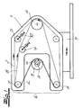
- the Fig. 1 shows a device for finishing a shaft.
- the apparatus comprises a tool carrier 1, an endless grinding belt 2 for finish machining of a workpiece 3 driven in rotation about its axis of rotation A, a grinding belt drive 4 which continuously drives the grinding belt 2 during workpiece machining, and a clamping device 5 for the grinding belt 2.
- the tool carrier 1 has a machining head 6 with two mutually spaced band deflections 7, which limit a working area L of the machining head 6.
- the band deflections 7 are formed as deflection rollers.
- the grinding belt 2 is guided over the deflection rollers 7 and runs in the working area L past the peripheral surface of the workpiece 3 to be machined.
- an endless support belt 8 is provided, which is stretched in the working area L of the machining head 6 parallel to the sanding belt 2 and in the working area L, the back of the sanding belt 2 is supported.
- the machining head 6 surrounds the circumferential surface of the workpiece 3 to be machined such that the abrasive belt 2 acted upon at the rear by the support belt 8 partially wraps around the workpiece 3 and bears against the workpiece surface to be machined along a circumferential section.
- the support belt 8 is tensioned by means of a separate second tensioning device 9. This second tensioning device 9 allows a targeted adjustment of the surface force exerted by the grinding belt 2 on the workpiece 3.
- the mechanical stress of the abrasive belt 2 is considerably reduced by the support belt 8, so that no special requirements must be made of the tensile strength of the abrasive belt 2.
- the sanding belt drive allows a specific adjustment of the cutting speed to the surface to be machined. The high cutting speeds required for achieving good finisher results are thus possible even with small workpiece diameters.
- the support band 8 is made of metal. The support belt 8 is guided together with the sanding belt 2 over the work area L limiting pulleys 7 and is in the embodiment according to Fig. 1 also driven by the sanding belt drive 4.
- the rectified speed of the two belts 2, 8 is identical, so that only a very small or no relative movement is present in the working area L between the grinding belt 2 and the support belt 8. As a result, a particularly low tensile stress of the abrasive belt 2 is ensured.
- the two tensioning devices 5, 9, the two belts 2, 8 and the sanding belt drive 4 are arranged together on the workpiece carrier 1.
- the tensioning devices 5, 9 have adjusting devices 10 for changing the belt lengths in the working area L.
- the wrap angle ⁇ between the grinding belt 2 and the workpiece surface to be machined is more than 90 °. As a result, a very uniform workpiece machining is possible.
- the tool carrier 1 is mounted on a feed carriage 11.
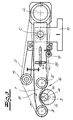
- Fig. 2 shows a further embodiment of the device according to the invention.
- the tool holder 1 follows here the orbital movement of the rotating about its axis of rotation
- a workpiece 3 which is formed in Fig. 2 as a crankshaft.
- the bearing shafts 12, 12 ' rotate synchronously and in phase with the workpiece 3 about their axes B, B'.
- the tool carrier 1 is mounted on circumferential surfaces 13, 13 'of the bearing shafts 12, 12', which correspond to the surface of the workpiece 3 to be machined.
- a separate support belt drive 14 is provided which drives the support belt 8 continuously.
- the rectified belt speeds of abrasive belt 2 and support belt 8 are identical in this embodiment, too.
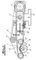
- the tool carrier 1 When in the Fig. 3 1, the tool carrier 1 is pivotally mounted about a rotation axis C, which is aligned parallel to the axis of rotation A of the workpiece 3 and is arranged in a lying between the machining head 6 and the sanding belt drive 4 tool carrier area. Trained as a swivel arm tool carrier 1 can follow by an oscillating pivotal movement of the rotating workpiece surfaces of the crankshaft 3, wherein the contact area between the grinding belt 2 and workpiece 3 within the working area L during the orbital motion moves accordingly. Due to the simple construction and operation, this embodiment allows a particularly cost finishing machining of crankshafts and camshafts.
- the distance of the sanding belt drive 4 from the axis of rotation C of the tool carrier 1 is set so that a substantial mass balance of the swinging about the rotation axis C masses is given. Furthermore, a mass 15 which is displaceably arranged along the tool carrier 1 is provided, which can be locked at a specific position of the tool carrier 1 before the start of processing, so that the desired contact force between the grinding belt 2 and the workpiece surface is ensured during processing. Also in this embodiment, the support belt 8 is also driven continuously with the same direction of movement and speed as the sanding belt 2 of the sanding belt drive 4.
Landscapes
- Engineering & Computer Science (AREA)
- Mechanical Engineering (AREA)
- Finish Polishing, Edge Sharpening, And Grinding By Specific Grinding Devices (AREA)
- Grinding And Polishing Of Tertiary Curved Surfaces And Surfaces With Complex Shapes (AREA)
Claims (8)
- Procédé pour l'usinage de finissage d'arbres, en particulier de vilebrequins et d'arbres à cames, une surface de pièce (3) tournant autour de son axe de rotation (A) étant traitée à l'aide d'une bande abrasive (2) sans fin entraînée de façon continue, la bande abrasive (2) étant tendue avec un dispositif de serrage (5) et étant soutenue sur sa face arrière dans la zone de la surface de pièce par une bande de soutien (8) sans fin, tendue dans cette zone parallèlement à la bande abrasive, caractérisé en ce que la bande abrasive (2) et la bande de soutien (8) entourent partiellement la pièce (3) de telle sorte que la bande abrasive (2) s'applique avec un angle d'enroulement (α) de plus de 90° à plat sur la surface périphérique à traiter de la pièce (3), qu'une bande de soutien (8) en métal est utilisée et que la bande de soutien (8) est commandée au moyen d'un second dispositif de serrage (5) séparé.
- Procédé selon la revendication 1, caractérisé en ce que la bande de soutien (8) est fixe pendant l'usinage de la surface de pièce.
- Procédé selon la revendication 1, caractérisé en ce que la bande de soutien (8) est entraînée également de façon continue et avec le même sens de déplacement que la bande abrasive (2).
- Procédé selon la revendication 3, caractérisé en ce que la vitesse de la bande de soutien (8) correspond à la vitesse de la bande abrasive (2).
- Dispositif avec porte-outil (1), la bande abrasive (2) sans fin pour l'usinage de finissage d'une pièce (3) entraînée de façon rotative autour de son axe de rotation (A),
un entraînement de bande abrasive (4), qui entraîne de façon continue la bande abrasive (2) pendant un usinage de pièce et
un dispositif de serrage (5) pour la bande abrasive (2),
le porte-outil (1) présentant une tête d'usinage (6) avec deux déviations de bande (7) espacées l'une de l'autre, lesquelles délimitent une zone de travail (L) de la tête d'usinage (6), la bande abrasive (2) étant guidée par les déviations de bande (7) de la tête d'usinage (6) et une bande de soutien (8) sans fin étant prévue, laquelle est tendue dans la zone de travail (L) de la tête d'usinage (6) parallèlement à la bande abrasive (2) et soutient dans la zone de travail (L) la face arrière de la bande abrasive (2), caractérisé en ce que, pour la mise en oeuvre du procédé selon l'une quelconque des revendications 1 à 4, la tête d'usinage (6) entoure en forme de fourche la surface périphérique à usiner de la pièce (3) de telle sorte que la bande abrasive (2), sollicitée côté arrière par la bande de soutien (8), entoure partiellement la pièce (3) et s'applique avec un angle d'enroulement (α) de plus de 90° à plat sur la surface périphérique à usiner de la pièce (3), et en ce que la bande de soutien (8) est en métal et est tendue à l'aide d'un second dispositif de tension (9). - Dispositif selon la revendication 5, caractérisé en ce que la bande de soutien (8) est guidée conjointement avec la bande abrasive (2) par les déviations de bande (6) délimitant la zone de travail (L) et est entraînée par l'entraînement de la bande abrasive (4) ou un entraînement séparé de bande de soutien (14).
- Dispositif selon la revendication 5 ou 6, caractérisé en ce que les dispositifs de serrage (5,9) et les entraînements (4, 14) pour la bande abrasive (2) et la bande de soutien (8) sont disposés sur le porte-outil (1).
- Dispositif selon l'une quelconque des revendications 5 à 7, caractérisé en ce que les dispositifs de serrage (5, 9) présentent des dispositifs de réglage (10) pour la modification des longueurs de bande dans la zone de travail (L).
Applications Claiming Priority (2)
| Application Number | Priority Date | Filing Date | Title |
|---|---|---|---|
| DE2003142134 DE10342134B4 (de) | 2003-09-12 | 2003-09-12 | Verfahren und Vorrichtung zur Finishbearbeitung von Kurbel- und Nockenwellen |
| DE10342134 | 2003-09-12 |
Publications (3)
| Publication Number | Publication Date |
|---|---|
| EP1514640A2 EP1514640A2 (fr) | 2005-03-16 |
| EP1514640A3 EP1514640A3 (fr) | 2006-03-01 |
| EP1514640B1 true EP1514640B1 (fr) | 2010-05-26 |
Family
ID=34129774
Family Applications (1)
| Application Number | Title | Priority Date | Filing Date |
|---|---|---|---|
| EP20040020483 Expired - Lifetime EP1514640B1 (fr) | 2003-09-12 | 2004-08-28 | Procédé et dispositif pour la finition d'arbres, en particulier de vilbrequins et d'arbres à cames |
Country Status (2)
| Country | Link |
|---|---|
| EP (1) | EP1514640B1 (fr) |
| DE (2) | DE10342134B4 (fr) |
Cited By (3)
| Publication number | Priority date | Publication date | Assignee | Title |
|---|---|---|---|---|
| WO2012065949A1 (fr) | 2010-11-17 | 2012-05-24 | Nagel Maschinen- Und Werkzeugfabrik Gmbh | Procédé et dispositif de finition de surfaces courbées de pièces au moyen d'une bande de finition |
| DE102011081918A1 (de) | 2011-08-31 | 2013-02-28 | Nagel Maschinen- Und Werkzeugfabrik Gmbh | Finishmaschine zur Finishbearbeitung gekrümmter Werkstückoberflächen an Werkstücken |
| TWI725225B (zh) * | 2017-08-30 | 2021-04-21 | 日商荏原製作所股份有限公司 | 研磨裝置及研磨方法 |
Families Citing this family (15)
| Publication number | Priority date | Publication date | Assignee | Title |
|---|---|---|---|---|
| SG134176A1 (en) * | 2006-01-09 | 2007-08-29 | Giken Sakata S Ltd | An apparatus for grinding a work piece |
| DE102007051047B4 (de) † | 2007-10-16 | 2023-03-23 | Nagel Maschinen- Und Werkzeugfabrik Gmbh | Andrückeinrichtung für Finishband sowie Vorrichtung und Verfahren zur Finishbearbeitung von Umfangsflächen an zylindrischen Werkstückabschnitten |
| EP2617522B1 (fr) | 2012-01-23 | 2014-01-15 | Supfina Grieshaber GmbH & Co. KG | Dispositif de traitement précis d'une surface périphérique de pièce usinée agencée de manière excentrique par rapport à un axe de pièce usinée |
| CN104139333B (zh) * | 2014-07-11 | 2016-05-18 | 山东金宝电子股份有限公司 | 铜箔表面处理机胶辊胶层的磨削方法及其使用的弧板夹具 |
| DE102015005915A1 (de) * | 2015-05-07 | 2016-11-10 | Jakob Löwer Inh. von Schumann GmbH & Co. KG | Entgratungsmaschine zum Entgraten von metallenen Werkstücken |
| DE102015221939B4 (de) * | 2015-11-09 | 2018-10-31 | Supfina Grieshaber Gmbh & Co. Kg | Finishbandvorrichtung und Verfahren zur finishenden Bearbeitung eines Werkstücks |
| CN106425768B (zh) * | 2016-09-23 | 2018-06-01 | 杭州新松机器人自动化有限公司 | 一种砂带浮动打磨机构 |
| CN107953207A (zh) * | 2017-12-26 | 2018-04-24 | 佛山市艾乐博机器人科技有限公司 | 一种打磨设备及其加工方法 |
| CN108177061B (zh) * | 2018-01-16 | 2019-10-18 | 苏州丰川电子科技有限公司 | 自动化金属表面处理装置 |
| CN108044728B (zh) * | 2018-01-18 | 2023-08-25 | 天津银雪环保科技服务有限公司 | 一种缠绕型圆模板及缠绕型圆模板的生产装置 |
| CN110026867B (zh) * | 2019-05-05 | 2021-06-15 | 钱泽袁 | 一种多角度加工辊轮制造装置 |
| CN112059852A (zh) * | 2020-09-30 | 2020-12-11 | 王后连 | 一种打磨带式带钢侧边毛刺清除装置 |
| CN115464519B (zh) * | 2022-10-26 | 2024-02-13 | 天津市春鹏预应力钢绞线有限公司 | 一种金属丝表面氧化层去除系统 |
| CN117564890A (zh) * | 2023-11-24 | 2024-02-20 | 宁波中策动力机电集团有限公司 | 一种随动砂带曲轴磨床及控制方法 |
| DE102025103433A1 (de) * | 2025-01-30 | 2026-07-30 | Fipe Ag | Rohrbandschleifeinheit zur Oberflächenbehandlung rohrförmiger Werkstücke und Verfahren zur Bearbeitung eines Rohres |
Family Cites Families (7)
| Publication number | Priority date | Publication date | Assignee | Title |
|---|---|---|---|---|
| DE7424571U (de) * | 1974-10-17 | Krugmann Gjt | Schleifvorrichtung | |
| DE844420C (de) * | 1951-01-06 | 1952-07-21 | Ernst Ebner | Bandschleifmaschine |
| DE3020393A1 (de) * | 1980-05-29 | 1982-01-28 | Friedr. August Picard KG, 5630 Remscheid | Vorrichtung zum bandschleifen |
| US5951377A (en) * | 1996-08-01 | 1999-09-14 | Radtec, Inc. | Microfinishing machine |
| JPH11165249A (ja) * | 1997-12-05 | 1999-06-22 | Tocalo Co Ltd | ベルト式研磨装置 |
| US6220946B1 (en) * | 1998-02-13 | 2001-04-24 | Philip D. Arnold | Active polishing of rotatable article surfaces |
| DE10342137B4 (de) * | 2003-09-12 | 2010-07-29 | Thielenhaus Technologies Gmbh | Vorrichtung und Verfahren zur Finishbearbeitung von Wellen, insbesondere von Kurbel- und Nockenwellen |
-
2003
- 2003-09-12 DE DE2003142134 patent/DE10342134B4/de not_active Expired - Fee Related
-
2004
- 2004-08-28 EP EP20040020483 patent/EP1514640B1/fr not_active Expired - Lifetime
- 2004-08-28 DE DE200450011200 patent/DE502004011200D1/de not_active Expired - Lifetime
Cited By (5)
| Publication number | Priority date | Publication date | Assignee | Title |
|---|---|---|---|---|
| WO2012065949A1 (fr) | 2010-11-17 | 2012-05-24 | Nagel Maschinen- Und Werkzeugfabrik Gmbh | Procédé et dispositif de finition de surfaces courbées de pièces au moyen d'une bande de finition |
| DE102010052311A1 (de) | 2010-11-17 | 2012-05-24 | Nagel Maschinen- Und Werkzeugfabrik Gmbh | Verfahren und Vorrichtung zur Finishbearbeitung gekrümmter Werkstückoberflächen an Werkstücken mittels Finishband |
| DE102011081918A1 (de) | 2011-08-31 | 2013-02-28 | Nagel Maschinen- Und Werkzeugfabrik Gmbh | Finishmaschine zur Finishbearbeitung gekrümmter Werkstückoberflächen an Werkstücken |
| WO2013030194A1 (fr) | 2011-08-31 | 2013-03-07 | Nagel Maschinen- Und Werkzeugfabrik Gmbh | Machine de finition de surfaces courbes de pièces à usiner |
| TWI725225B (zh) * | 2017-08-30 | 2021-04-21 | 日商荏原製作所股份有限公司 | 研磨裝置及研磨方法 |
Also Published As
| Publication number | Publication date |
|---|---|
| EP1514640A2 (fr) | 2005-03-16 |
| EP1514640A3 (fr) | 2006-03-01 |
| DE10342134A1 (de) | 2005-04-07 |
| DE10342134B4 (de) | 2009-09-03 |
| DE502004011200D1 (de) | 2010-07-08 |
Similar Documents
| Publication | Publication Date | Title |
|---|---|---|
| DE10342134B4 (de) | Verfahren und Vorrichtung zur Finishbearbeitung von Kurbel- und Nockenwellen | |
| DE60000670T2 (de) | Bandschleifmaschine mit um eine Umlaufbahn bewegtem Schleifband | |
| DE4226708C2 (de) | Bandschleifmaschine | |
| DE9116540U1 (de) | Vorrichtung zum Schleifen von Kurbelzapfenlagern an Kurbelwellen | |
| DE19634839A1 (de) | Feinstbearbeitung mit Vibrationskopf | |
| EP3135433A2 (fr) | Unite de traitement de surfaces circonferentielles, machine-outil et procede de fonctionnement | |
| DE19825698A1 (de) | Bandschleifmaschine | |
| DE19723306C2 (de) | Verfahren und Vorrichtung zum Schleifen oder Polieren von Stirnflächen plattenförmiger Körper | |
| EP0276439B1 (fr) | Procédé pour meuler intérieurement des torages longs de très petit diamètre dans des pièces et dispositif pour la mise en oeuvre de ce procédé | |
| EP2636482B1 (fr) | Système de traitement de pièce usinée et procédé de traitement très fin d'une pièce usinée | |
| EP1514643B1 (fr) | Procédé pour l'usinage de finition de la surface de révolution d'arbres | |
| DE3312133A1 (de) | Schaumstoff-formschneidemaschine, insbesondere fuer numerische werkzeugsteuerung | |
| EP2596907A1 (fr) | Dispositif de finition d'une surface de pièce usinée incurvée | |
| DE19821982C2 (de) | Profil-Bandschleifmaschine | |
| EP1514641A1 (fr) | Appareil pour le finissage des arbres, en particulier villebriquins et arbres à cames | |
| DE10342137B4 (de) | Vorrichtung und Verfahren zur Finishbearbeitung von Wellen, insbesondere von Kurbel- und Nockenwellen | |
| DE3918847C2 (fr) | ||
| DE68907730T2 (de) | Vorrichtung zur Kantenbearbeitung von laufenden Blechen. | |
| DE1652119A1 (de) | Verfahren und Maschine zum Feinstbearbeiten der Mantelflaechen von Tonnenrollen oder dergleichen Werkstuecken | |
| EP1424162B1 (fr) | Machine à traitement de surface avec disposition de roulements | |
| DE102018101339A1 (de) | Bandfinishvorrichtung | |
| DE2346431A1 (de) | Verfahren und vorrichtung zum abschleifen einer oberflaeche | |
| DE480136C (de) | Antrieb der Schleifspindel an Schleifmaschinen | |
| DE1181504B (de) | Vorrichtung zum Anschaerfen der Enden von endlos zu machenden, ein- oder mehrschichtigen Treibriemen bzw. Foerderbaendern | |
| DE102015221939B4 (de) | Finishbandvorrichtung und Verfahren zur finishenden Bearbeitung eines Werkstücks |
Legal Events
| Date | Code | Title | Description |
|---|---|---|---|
| PUAI | Public reference made under article 153(3) epc to a published international application that has entered the european phase |
Free format text: ORIGINAL CODE: 0009012 |
|
| AK | Designated contracting states |
Kind code of ref document: A2 Designated state(s): AT BE BG CH CY CZ DE DK EE ES FI FR GB GR HU IE IT LI LU MC NL PL PT RO SE SI SK TR |
|
| AX | Request for extension of the european patent |
Extension state: AL HR LT LV MK |
|
| PUAL | Search report despatched |
Free format text: ORIGINAL CODE: 0009013 |
|
| AK | Designated contracting states |
Kind code of ref document: A3 Designated state(s): AT BE BG CH CY CZ DE DK EE ES FI FR GB GR HU IE IT LI LU MC NL PL PT RO SE SI SK TR |
|
| AX | Request for extension of the european patent |
Extension state: AL HR LT LV MK |
|
| 17P | Request for examination filed |
Effective date: 20060318 |
|
| AKX | Designation fees paid |
Designated state(s): DE FR GB IT |
|
| 17Q | First examination report despatched |
Effective date: 20090514 |
|
| GRAP | Despatch of communication of intention to grant a patent |
Free format text: ORIGINAL CODE: EPIDOSNIGR1 |
|
| GRAS | Grant fee paid |
Free format text: ORIGINAL CODE: EPIDOSNIGR3 |
|
| GRAA | (expected) grant |
Free format text: ORIGINAL CODE: 0009210 |
|
| AK | Designated contracting states |
Kind code of ref document: B1 Designated state(s): DE FR GB IT |
|
| REG | Reference to a national code |
Ref country code: GB Ref legal event code: FG4D Free format text: NOT ENGLISH |
|
| REF | Corresponds to: |
Ref document number: 502004011200 Country of ref document: DE Date of ref document: 20100708 Kind code of ref document: P |
|
| PLBE | No opposition filed within time limit |
Free format text: ORIGINAL CODE: 0009261 |
|
| STAA | Information on the status of an ep patent application or granted ep patent |
Free format text: STATUS: NO OPPOSITION FILED WITHIN TIME LIMIT |
|
| 26N | No opposition filed |
Effective date: 20110301 |
|
| REG | Reference to a national code |
Ref country code: DE Ref legal event code: R097 Ref document number: 502004011200 Country of ref document: DE Effective date: 20110228 |
|
| PGFP | Annual fee paid to national office [announced via postgrant information from national office to epo] |
Ref country code: GB Payment date: 20110830 Year of fee payment: 8 Ref country code: FR Payment date: 20110912 Year of fee payment: 8 Ref country code: DE Payment date: 20110830 Year of fee payment: 8 |
|
| PGFP | Annual fee paid to national office [announced via postgrant information from national office to epo] |
Ref country code: IT Payment date: 20110831 Year of fee payment: 8 |
|
| GBPC | Gb: european patent ceased through non-payment of renewal fee |
Effective date: 20120828 |
|
| REG | Reference to a national code |
Ref country code: FR Ref legal event code: ST Effective date: 20130430 |
|
| PG25 | Lapsed in a contracting state [announced via postgrant information from national office to epo] |
Ref country code: IT Free format text: LAPSE BECAUSE OF NON-PAYMENT OF DUE FEES Effective date: 20120828 |
|
| PG25 | Lapsed in a contracting state [announced via postgrant information from national office to epo] |
Ref country code: DE Free format text: LAPSE BECAUSE OF NON-PAYMENT OF DUE FEES Effective date: 20130301 Ref country code: GB Free format text: LAPSE BECAUSE OF NON-PAYMENT OF DUE FEES Effective date: 20120828 |
|
| PG25 | Lapsed in a contracting state [announced via postgrant information from national office to epo] |
Ref country code: FR Free format text: LAPSE BECAUSE OF NON-PAYMENT OF DUE FEES Effective date: 20120831 |
|
| REG | Reference to a national code |
Ref country code: DE Ref legal event code: R119 Ref document number: 502004011200 Country of ref document: DE Effective date: 20130301 |